Page 935 of 2490

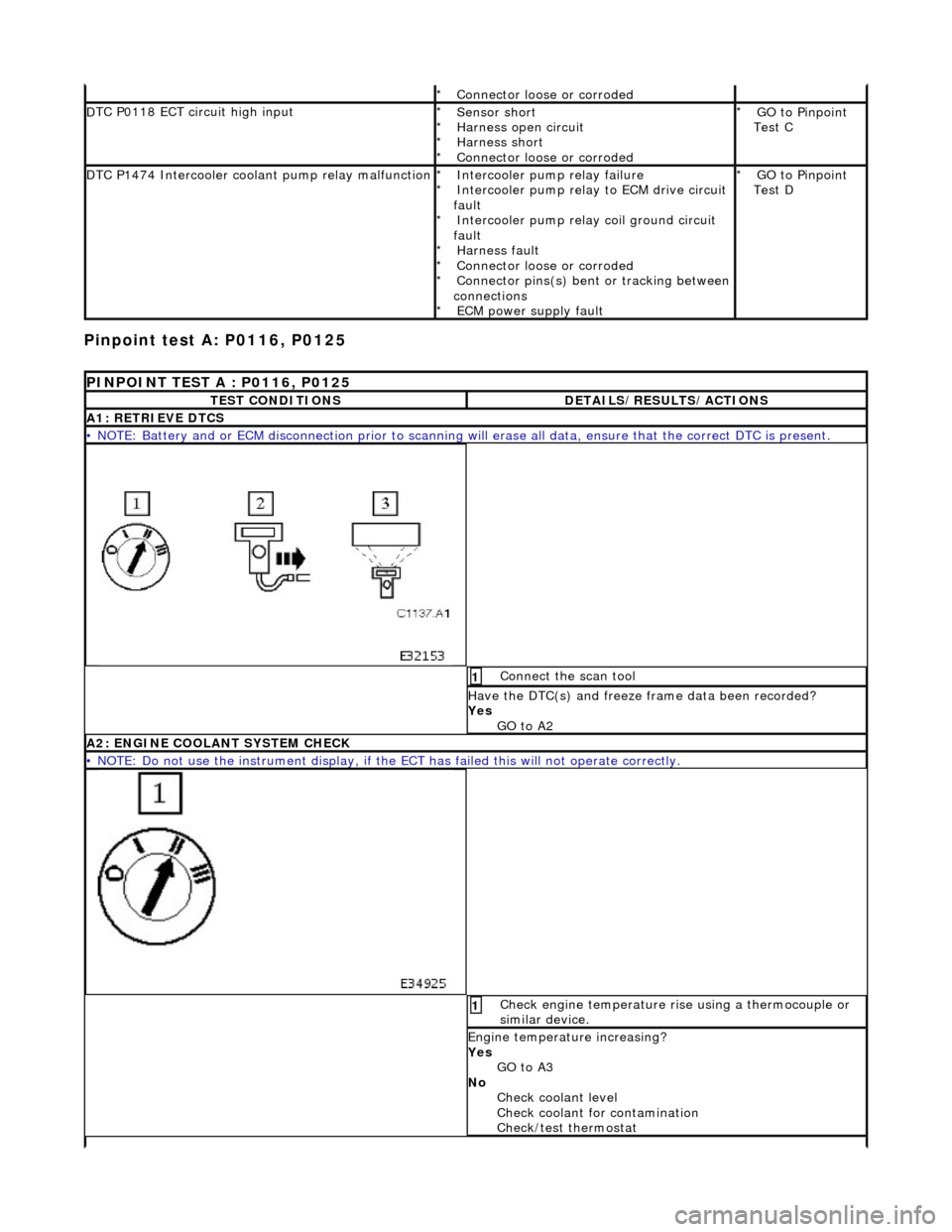
Pinpoint test
A: P0116, P0125
Connector
loose or corroded
*
D
TC P0118 ECT circuit high input
Sensor short
Harness open circui
t
Harness short
Connector loose or corroded
*
*
*
*
GO to Pinpoint
Test C
*
D
TC P1474 Intercooler coolant pump relay malfunction
Intercooler pump relay
failure
Intercooler pump relay to ECM drive circuit
fault Intercooler pump relay coil ground circuit
fault Harness fault
Connector loose or corroded
Connector pins(s) bent or tracking between
connections ECM power supply fault
*
*
*
*
*
*
*
GO to Pinpoint
Test D
*
P
INPOINT TEST A : P0116, P0125
T
EST CONDITIONS
D
ETAILS/RESULTS/ACTIONS
A1
: RETRIEVE DTCS
•
NOTE: Battery and or ECM disconnection prior to scanning wi
ll erase all data, ensure that the correct DTC is present.
Conne
ct the scan tool
1
Have the DTC(s) and fr
eeze
frame data been recorded?
Yes GO to A2
A2: ENGINE
COOLANT SYSTEM CHECK
•
NOTE: Do not use the instrument display, if th
e ECT has failed this will not operate correctly.
Chec
k engine temperature rise using a thermocouple or
similar device.
1
Engine
temperature increasing?
Yes GO to A3
No Check coolant level
Check coolant for contamination
Check/test thermostat
Page 937 of 2490
I
gnition switch to position 0
1
Di
sconnect EM011
Inside E
CM housing
2
Me
asure the resistance between EM011/009 and
PI004/002.
3
I
s the resistance < 0.5 OHM?
Yes GO to A5
No Inspect harness / connector EM011/009, PI004/002 and
PI001/005 for corrosion, damage , bent or pushed back
pins. Repair as necessary and test the system for normal
operation.
A5: CHECK
HARNESS CONTINUITY
•
NOTE: To avoid a spurious result, disconnect connectors PI042 and PI006 (electronic throttle body) and PI035 (MAF
meter).
Page 938 of 2490
Ig
nition switch to position 0
1
Di
sc
onnect EM010
Inside E
C
M housing
2
Me
asure
the resistance between EM011/012 and
PI004/001.
3
I s
the resistance < 0.5 OHM?
Yes GO to A6
No Inspect harness/connector EM011/012, PI004/001,
PI001/006 and splices EMS02 / PIS01 for corrosion,
damage, bent or pushed back pins and repair as required.
Test the system for normal operation.
A6: CHECK HARNESS
CONTINUITY
•
NOTE
: Do not reconnect electronic thro
ttle body connectors PI042 and PI006.
Page 939 of 2490
Pinpoint test
B: P0117
I
gnition switch to position 0
1
Di
sconnect EM010
Inside E
CM housing
2
Meas
ure the resistance between the ECM connector
EM010/020 and the ECT connector PI004/001.
3
I
s the resistance < 0.5 OHM?
Yes GO to A7
No Inspect harness / connector EM010/020, PI004/001,
PI001/006 and splices EMS02 / PIS01 for corrosion,
damage, bent or pushed back pins. Repair as necessary
and reconnect all connectors.
Test the system for normal operation.
A7
: END
Perform
appropriate service drive cycle and check for the
presence of DTC.
1
Has
the fault code cleared?
Yes STOP
No Contact Jaguar Service
P
INPOINT TEST B : P0117
T
EST CONDITIONS
D
ETAILS/RESULTS/ACTIONS
B1
: RETRIEVE DTCS
•
NOTE: Battery and or ECM disconnection prior to scanning wi
ll erase all data, ensure that the correct DTC is present.
Page 941 of 2490
I
gnition switch to position 0
1
Di
sconnect EM011
Inside E
CM housing
2
D
isconnect PI004
Re
ar of top hose
3
Meas
ure the resistance between the ECM connector
EM011/009 and the ECT connector PI004/002.
4
I
s the resistance < 0.5 OHM?
Yes GO to B4
No Inspect harness / connector EM011/009, PI004/002 and
PI001/005 for corrosion, damage , bent or pushed back
pins. Repair as necessary and test the system for normal
operation.
B4: CHECK
HARNESS CONTINUITY
•
NOTE: To avoid a spurious result, disconnect connectors PI042 and PI006 (electronic throttle body) and PI035 (MAF
meter).
Page 942 of 2490
Ig
nition switch to position 0
1
Di
sc
onnect EM010
Inside E
C
M housing
2
Meas
ure t
he resistance between the ECM connector
EM011/012 and the ECT connector PI004/001.
3
I s
the resistance < 0.5 OHM?
Yes GO to B5
No Inspect harness / connector EM011/012, PI004/001,
PI001/006 and splices EMS02 / PIS01 for corrosion,
damage, bent or pushed back pins. Repair as necessary,
reconnect all connectors. Te st the system for normal
operation.
B5: CHECK HARNESS
CONTINUITY
•
NOTE
: Do not reconnect electronic thro
ttle body connectors PI042 and PI006.
Page 943 of 2490
I
gnition switch to position 0
1
Di
sconnect EM010
Inside E
CM housing
2
Meas
ure the resistance between the ECM connector
EM010/020 and the ECT connector PI004/001.
3
I
s the resistance < 0.5 OHM?
Yes GO to B6
No Inspect harness / connector EM010/020, PI004/001,
PI001/006 and splices EMS02 / PIS01 for corrosion,
damage, bent or pushed back pins. Repair as required and
reconnect all connectors. Te st the system for normal
operation.
B6:
CHECK FOR SHORT TO B+
Page 944 of 2490
Pinpoint test C: P0118
I
g
nition switch to position 0
1
Di
sc
onnect EM011
Inside E
C
M housing
2
I
g
nition switch to position II
3
Measure the
voltage betwee n pin
s 9 and 12 of the
connector.
4
Is th e volt
age > 1 V?
Yes Inspect harness / connector EM011/009, PI004/002,
PI001/005 and splices EMS02 / PIS01 for corrosion,
damage, bent or pushed back pins. Repair as required and
reconnect all connectors. Te st the system for normal
operation.
No GO to B7
B7: EN
D
Perform
a
ppropriate service drive cycle and check for the
presence of DTC.
1
Has th
e fault code cleared?
Yes STOP
No Contact Jaguar Service
PINPOINT TES
T C : P0118
T
E
ST CONDITIONS
D
E
TAILS/RESULTS/ACTIONS
C1
: RETRIEVE DTC
S
•
NOTE
: Battery and or ECM disconnection prior to scanning wi
ll erase all data, ensure that the correct DTC is present.