Page 723 of 2490
Installation
24. Disconnect the fuel return hose.
1. Disconnect the fuel retu rn hose at the Quick Fit
connector, using special tool 310 - 054.
25. Remove the inlet manifold.
1. Remove the ten bolts which secure the inlet manifold.
2. Remove the inlet manifold
26. Remove and discard the eight se als from the inlet manifold
ports.
1. Clean all parts and relevant mating faces.
2. Fit eight new seals to the inlet manifold ports.
Page 724 of 2490
3. Fit the inlet manifold to the engine.
1. Fit the inlet manifold.
2. Fit the ten bolts which secure the inlet manifold.
4. Connect the fuel feed hose.
1. Connect the fuel feed hose at the Quick Fit connector. Ensure that the hose is fully seated to the feed pipe.
5. Connect the fuel return hose.
1. Connect the fuel return hose at the Quick Fit
connector. Ensure th at the hose is fully seated to the
feed pipe.
6. Reconnect the electrical connector to each fuel injector.
Page 754 of 2490
Engine - Oil Pressure Switch
In-vehicle Repair
Removal
Installation
1.
Raise vehicle on four post ramp.
2. Remove oil pressure switch.
Disconnect connector.
Remove oil pressure switch from oil filter head.
1. NOTE: Fit new sealing washer to oil pressure switch.
Installation is reverse of removal.
Page 896 of 2490
Engine - Engine
Removal
Removal
Special Tool(s)
Engine Lifting Brackets
303-536
Quick Fit Connector Release Tool
310-044
Quick Fit Connector Release Tool
310-054
Quick Fit Connector Release Tool
303-623
Fuel Injection Pressure Test Equipment
310-058
1. Park the vehicle on a four post ramp, over which, an overhead
lifting crane is available, and set the gear selector to 'N'.
The crane should be rated at a minimum of 500 kg Safe
Working Load and have suffici ent fore and aft movement
to traverse the engine assemb ly clear of the vehicle.
Do not apply the handbrake, but use wedges to chock one
wheel to prevent movement of the vehicle.
2. Open the engine compartment and fit paintwork protection
sheets.
3. Disconnect the batt ery ground cable.
Remove the battery cover.
Page 900 of 2490
2. Release the hose, expansion tank to recovery tank.
3. Release the hose, expansion tank to radiator.
20. Fit blanking plugs to the pipes and the tank.
21. Remove the expansion tank from the mounting.
1. Disconnect the coolant level sensor connector.
2. Remove the nuts which secure the tank.
22. Remove the expansion tank from the vehicle.
1. It may be necessary to us e a pipe clamp to clamp the
bottom hose branch.
2. Release the pipe clip an d move it along the pipe.
3. Disconnect the tank from the bottom hose and remove it from the vehicle.
23. Empty any remaining coolant from the expansion tank into a
drain tray.
24. Remove the cloth from the engine and clean any spillage from
the engine bay.
25. Disconnect the radiator breather hose.
Release the Quick-Fit hose (radiator to expansion tank)
using 303 - 623, and disconnect the hose from the
radiator.
26. Remove the twin fan and motor assembly. Refer to Operation
26.25.12.
Page 906 of 2490

the pipes. Allow the oil to drain.
3. Remove the O-ring seals and fit blanking plugs to the
pipes and to the mating unions on the engine.
51. Lower the ramp.
52. Disconnect the generator suppres sion module (where fitted)
harness.
Disconnect the harness multi-plug and reposition the
harness from under the suppression module.
53. Disconnect the starter motor power cable, at the right hand
side engine compartment enclosure.
1. Disconnect the multi-plug, engine management harness to starter motor.
2. Reposition the protective boot from the starter motor
power stud.
3. Remove the nut and disc onnect the power cable.
Cut the tie strap which secures the power cable to the
enclosure and route the cable into the engine bay.
54. Disconnect the P.I. harness from the engine management
harness.
1. Release the bolt which secures the P.I. harness multi-plug to the engine management harness.
2. Disconnect the multi-plug.
3. Remove the nut which secures the engine management harness multi-plug to the mounting
bracket.
4. Reposition the multi-plug from the bracket.
55. Disconnect the transmission rota ry switch harness connector.
Reposition and disconnect the harness multi-plug.
Page 907 of 2490

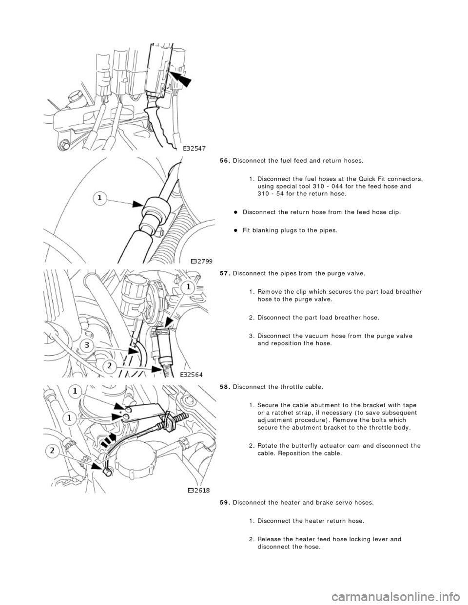
56. Disconnect the fuel feed and return hoses.
1. Disconnect the fuel hoses at the Quick Fit connectors,
using special tool 310 - 044 for the feed hose and
310 - 54 for the return hose.
Disconnect the return hose from the feed hose clip.
Fit blanking plugs to the pipes.
57. Disconnect the pipes from the purge valve.
1. Remove the clip which secu res the part load breather
hose to the purge valve.
2. Disconnect the part load breather hose.
3. Disconnect the vacuum hose from the purge valve and reposition the hose.
58. Disconnect the throttle cable.
1. Secure the cable abutment to the bracket with tape or a ratchet strap, if nece ssary (to save subsequent
adjustment procedure). Remove the bolts which
secure the abutment bracke t to the throttle body.
2. Rotate the butterfly actuator cam and disconnect the cable. Reposition the cable.
59. Disconnect the heater and brake servo hoses.
1. Disconnect the he ater return hose.
2. Release the heater feed hose locking lever and
disconnect the hose.
Page 908 of 2490
3. Disconnect the brake servo hose.
60. Fit engine rear lifting eyes (303 - 536).
61. Traverse the hoist to the engine compartment and lower it to
working height.
62. Fit lifting chains to the hoist and connect to each engine
lifting eye. Use longer chains to the rear lifting eyes to allow
the engine to tilt rearwards wh en removing from the vehicle.
63. Remove the engine front mounting nuts.
64. Raise the ramp.
65. Disconnect the transmission connector.
1. Release the lever lock on the transmission harness
multi-plug.
2. Disconnect the connector.
66. Disconnect the transmission selector cable.