1998 JAGUAR X308 timing
[x] Cancel search: timingPage 528 of 2490

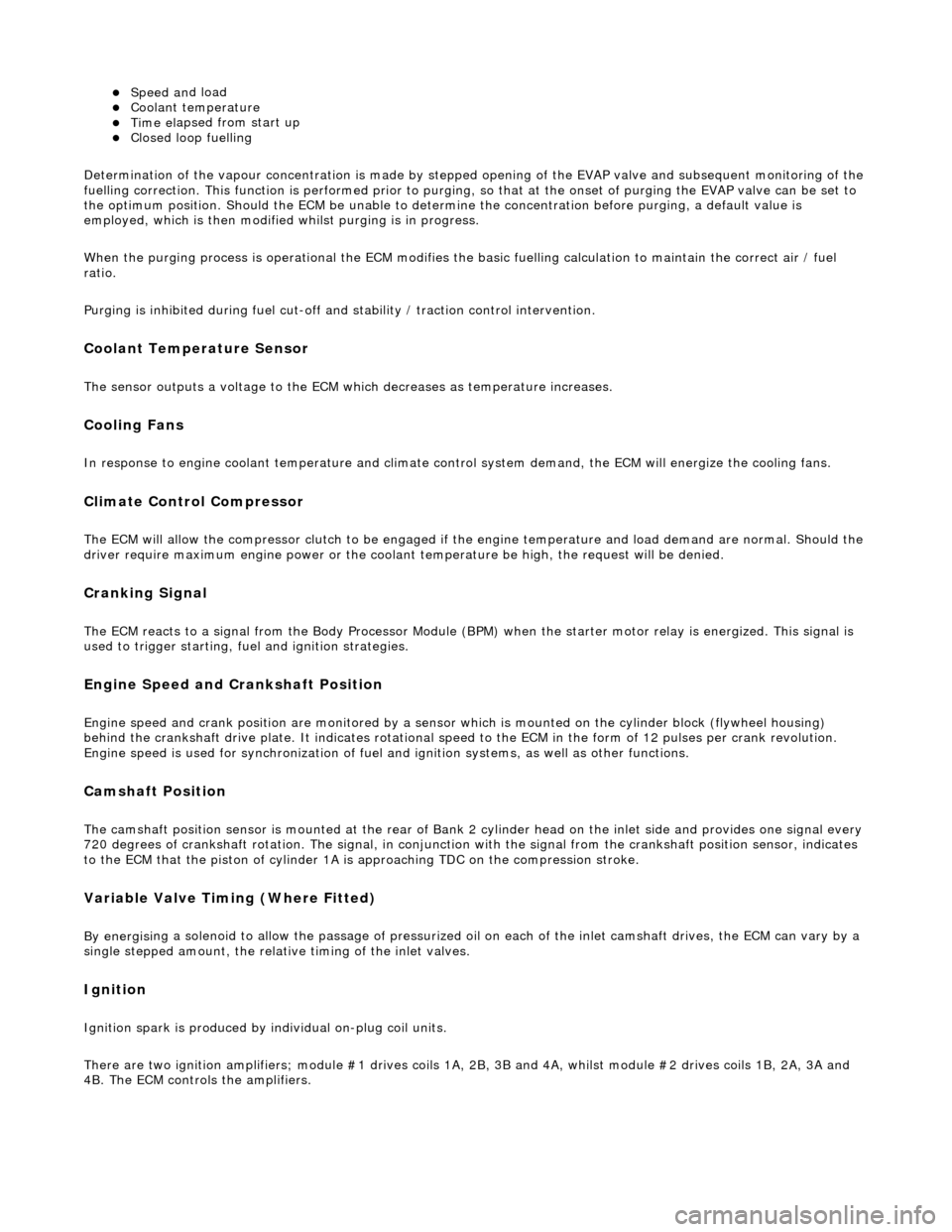
Speed an
d load
Coo
l
ant temperature
Ti
me el
apsed from start up
Cl
osed l
oop fuelling
Determination of the vapour concentration is made by stepped opening of the EVAP valve and subsequent monitoring of the
fuelling correction. This function is performed prior to purging, so that at the onse t of purging the EVAP valve can be set to
the optimum position. Should the ECM be unable to determine the concentration before purging, a default value is
employed, which is then modified whilst purging is in progress.
When the purging process is operational th e ECM modifies the basic fuelling calculation to maintain the correct air / fuel
ratio.
Purging is inhibited during fuel cut-off and stability / traction control intervention.
Coolant Temperature Sen
sor
Th
e
sensor outputs a voltage to the ECM which decreases as temperature increases.
Cooling Fans
In response to engi
ne coolant temperat
u
re and climate control system demand, the ECM will energize the cooling fans.
Climate Control Compressor
The E
C
M will allow the compressor clutch to be engaged if th
e engine temperature and load demand are normal. Should the
driver require maximum engine powe r or the coolant temperature be high, the request will be denied.
Cranking Signal
The ECM reacts to a signal fr
om th
e Body Processor Module (BPM) when the starter motor relay is energi
zed. This signal is
used to trigger starting, fu el and ignition strategies.
Engine Speed and Cranksh
aft Position
Engine
speed and cran
k position are moni
tored by a sensor which is mounted on the cylinder block (flywheel housing)
behind the crankshaft drive plat e. It indicates rotational speed to the ECM in the form of 12 pulses per crank revolution.
Engine speed is used for synchronization of fuel an d ignition systems, as well as other functions.
Camshaft Position
The ca
mshaft position sensor is mounted at
the rear of Bank 2 cylinder head on the inlet side and provides one signal every
720 degrees of crankshaft rotation. The signal, in conjunction with the signal from the crankshaft position sensor, indicates
to the ECM that the piston of cylinder 1A is approaching TDC on the compression stroke.
Variable Valve
Timing (Where Fitted)
By energi
si
ng a solenoid to allow the pass
age of pressurized oil on each of the inle t camshaft drives, the ECM can vary by a
single stepped amount, the relati ve timing of the inlet valves.
Ign
ition
Ignit
i
on spark is produced by
individual on-plug coil units.
There are two ignition amplifiers; module #1 drives coils 1A, 2B, 3B and 4A, whilst module #2 drives coils 1B, 2A, 3A and
4B. The ECM controls the amplifiers.
Page 529 of 2490

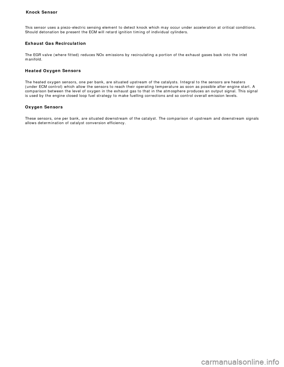
Thi
s sensor uses a piezo-electric sensing element to detect kn
ock which may occur under acceleration at critical conditions.
Should detonation be present the ECM will retard ignition timing of individual cylinders.
Exhaust G
as Recirculation
The EGR
valve (where fitted) reduces NOx
emissions by recirculating a portion of the exhaust gases back into the inlet
manifold.
Heated Oxyg
en Sensors
The h
eated oxygen sensors, one per bank, are situated upstream of the catalysts. Integral
to the sensors are heaters
(under ECM control) which allow the sensor s to reach their operating temperature as soon as possible after engine start. A
comparison between the level of oxygen in the exhaust gas to that in the atmosphere produces an output signal. This signal
is used by the engine closed loop fuel strategy to make fuelling corrections and so control overall emission levels.
Oxygen Sensors
Thes
e sensors, one per bank, are situated downstream of the
catalyst. The comparison of upstream and downstream signals
allows determination of cata lyst conversion efficiency.
Knock Sensor
Page 530 of 2490

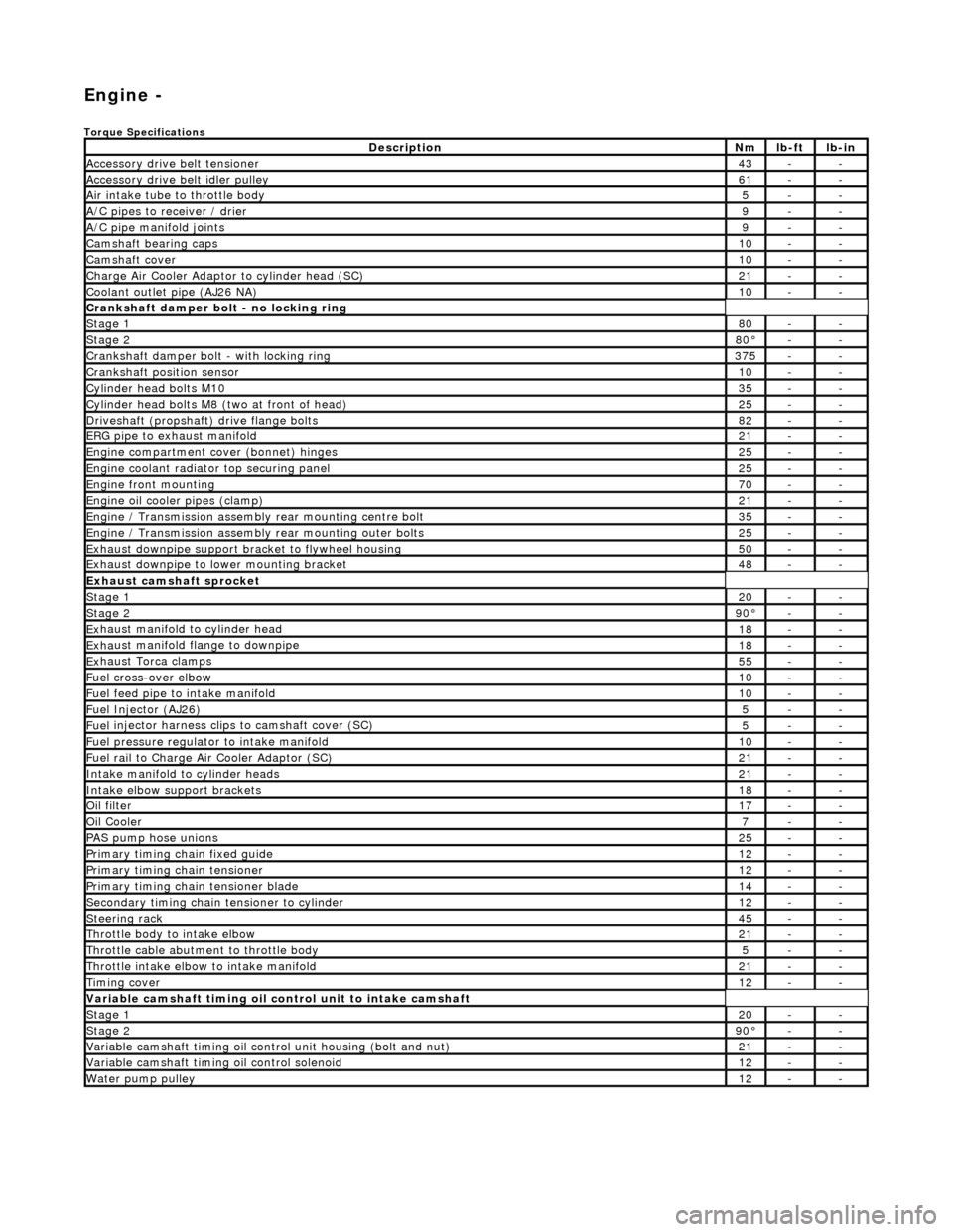
Engi
ne -
Torqu
e Specifications
De
s
cription
Nmlb
-
ft
lb
-
in
A
ccessory
drive belt tensioner
43--
A
ccessory
drive belt idler pulley
61--
Air in
ta
ke tube to throttle body
5--
A/C
pipes t
o receiver / drier
9--
A/C pipe m
anifold joints
9--
Camsh
aft bearin
g caps10--
Ca
msh
aft cove
r10--
Ch
arge Air Co
oler Adaptor to cylinder head (SC)
21--
Co
olan
t outlet pipe (AJ26 NA)
10--
Cran
kshaft damper bolt - no lockin
g ring
St
ag
e 1
80--
Stag
e 2
80°--
C
r
ankshaft damper bolt - with locking ring
37
5--
Cra
nkshaft position sensor
10--
Cy
li
nder head bolts M10
35--
Cy
lin
der head bolts M8 (two at front of head)
25--
Driv
es
haft (propshaft) drive flan
ge bo
l
ts
82--
ERG p
i
pe to exhaust manifold
21--
Engi
ne compartment cover (bonnet) hinges
25--
En
gine
coolant radiator top securing panel
25--
E
ng
ine front mounting
70--
En
gine
oil cooler pipes (clamp)
21--
En
gi
ne / Transmission assembly rear mounting centre bolt
35--
En
gi
ne / Transmission assembly rear mounting outer bolts
25--
Ex
ha
ust downpipe support bracket to flywheel housing
50--
Ex
ha
ust downpipe to lower mounting bracket
48--
E
x
haust camshaft sprocket
St
age 120--
Stage 290 °--
Ex
haust manifold to cylinder head
18--
Ex
ha
ust manifold flange to downpipe
18--
E
x
haust Torca clamps
55--
Fuel cross-over elbo
w
10--
Fu
el f
eed pipe to intake manifold
10--
Fuel
Injector (AJ
26)
5--
Fuel
injector ha
rness clips to camshaft cover (SC)
5--
Fu
el p
ressure re
gu
l
ator to intake manifold
10--
F
u
el rail to Char
ge
A
ir Cooler Adaptor (SC)
21--
In
ta
ke manifold to cylinder heads
21--
Inta
ke elbow support brackets
18--
Oil f
i
lter
17--
Oil C
o
oler
7--
P
AS pu
mp hose unions
25--
P
r
imary timing chain fixed guide
12--
P
r
imary timing chain tensioner
12--
Pr
imary timing chain tensioner blade
14--
S
e
condary timing chain tensioner to cylinder
12--
S
t
eerin
g ra
ck45--
Thro
ttle body to intake elbow
21--
Th
ro
ttle cable abutment to throttle body
5--
Th
ro
ttle intake elbow to intake manifold
21--
Ti
mi
ng cover
12--
Variable camshaft t
i
ming oil control unit to intake camshaft
St
ag
e 1
20--
St
ag
e 2
90
°--
Var
iable camshaft timing oil control unit housing (bolt and nut)
21--
Va
ria
ble camshaft timi
ng oil control solenoid
12--
Wa
ter pump pulley
12--
Page 552 of 2490

Engine - Connecting Rod Bearings
In-vehic
le Repair
Remov
a
l
1.
Disc
onnect the batt
ery ground cable.
Re
move the battery cover.
2. Open the engine compartment and fit paintwork protection
sheets.
3. Remove the engine compartmen t cover. Refer to operation
76.16.01.
4. Remove the twin fan and motor assembly. Refer to Operation
26.25.12.
5. Remove the timing cover and al l associated components, as
detailed in Operation 12.65.01.
6. Remove both front wheel and tyre assemblies. Refer to
Operation 74.20.05.
7. Remove the undertray. Re fer to Operation 76.22.90.
8. Remove the front crossmember fo r access. Refer to Operation
76.10.05.
9. Drai
n the engine oil.
1. Position the waste oil bowser.
2. Remove the drain plug from the oil pan and drain the engine oil.
Install a new sealing wash er to the
drain plug.
Wipe the drain plug an
d
install
it to the oil pan to prevent
oil dripping.
Move the oil bowser away f
rom the vehicle.
10 . Re
move the oil pan.
1. Remove the eighteen bolt s which secure the oil pan
to the oil pan body.
2. Remove the oil pan.
3. Remove the gasket from the oil pan body assembly.
11. Remove the oil pan body a ssembly. Refer to Operation
Page 556 of 2490

5.
Install the front cros smember. Refer to Operat
ion 76.10.05.
6. Install the undert ray. Refer to Operation 76.22.90.
7. Install both front wheel and tyre assemblies. Refer to
Operation 74.20.05.
8. Install the timing cover and al l associated components, as
detailed in Operation 12.65.01.
9. Install the twin fan and motor assembly. Refer to Operation
26.25.12.
10. NOTE: When the engine is star ted from cold and run for a
short period only, before being swit ched off, a quantity of oil will
be 'hung up' within the engine because it is not up to operating
temperature.
Should the oil level subsequently be topped-up, the level could
become too high, causing oil burning.
Typically, 0.875 L is hung up.
Refill the engine with the correct specification engine oil.
11. Connect the battery and in stall the battery cover.
Refe
r to the Battery Reconnection Procedure 86.15.15.
12. Check the oil level and start th e engine. Check for leaks and
that the engine runs correctly.
13. Install the engine compartmen t cover. Refer to operation
76.16.01.
14. Remove the paintwork protection sheets and close the engine
compartment cover.
Page 559 of 2490

I
nstallation
11
.
Remove the crankshaft front seal.
1. Install and tighten the removal tool 303-541 to the crankshaft front seal.
2. Tighten the centre bolt of the tool to extract the seal.
R
emove the tool an
d seal assembly.
Separate the seal
from the tool.
12. Very carefully clean the thread s of the crankshaft, using a
plug tap M16x2, to remove all old cured sealant.
Kee
p the tap horizontal. Do not enlarge the crankshaft
thread - remove sealant only.
13. Clean all relevant parts and faces.
1. Loc
ate the new oil seal into the timing cover.
1. Remove the transit ring from the oil seal.
2. Position the seal to the timing cover.
2. Inst
all the new oil seal to the timing cover.
1. Install oil seal replacer tool 303-542 to the oil seal.
2. Use the nut and bolt provided with the tool, to fully seat the seal to the timing cover. Only tighten the nut
sufficiently to locate the seal and no more, or the
timing cover could become distorted.
All
ow the tool to stay in posi
tion against the seal for at
least five seconds.
R
emove the special tool from the seal.
Page 563 of 2490

I
nstallation
12
.
Remove the crankshaft front seal.
1. Install and tighten the removal tool 303-541 to the crankshaft front seal.
2. Tighten the centre bolt of the tool to extract the seal.
R
emove the tool an
d seal assembly.
Separate the seal
from the tool.
13. Very carefully clean the thread s of the crankshaft, using a
plug tap M16x2, to remove all old cured sealant.
Kee
p the tap horizontal. Do not enlarge the crankshaft
thread - remove sealant only.
14. Clean all relevant parts and faces.
1. Loc
ate the new oil seal into the timing cover.
1. Remove the transit ring from the oil seal.
2. Position the seal to the timing cover.
2. Inst
all the new oil seal to the timing cover.
1. Install oil seal replacer tool 303-542 to the oil seal.
2. Use the nut and bolt provided with the tool, to fully seat the seal to the timing cover. Only tighten the nut
sufficiently to locate the seal and no more, or the
timing cover could become distorted.
All
ow the tool to stay in posi
tion against the seal for at
least five seconds.
R
emove the special tool from the seal.
Page 565 of 2490

Engine - Crankshaft
Inner Sp
rocket4.0L NA V8 - AJ27
In-v
ehicle Repair
Remov
al
S
pecial Tool(s)
Camshaft setting
3
03 - 530
T
iming chain tensioning
303 - 532
Wedges, primary ch
ain
303 - 533
Cranksh
aft setting
303 - 531
1. Open the engine compartment and fit paintwork protection
sheets.
2. Set the engine compartment cover to the service access
position.
3. Di
sconnect the batt
ery ground cable.
R
emove the battery cover.
4. Remove the Timing Co ver. Refer to Operation 12.65.01 in this
Section.
5. Remove the VVT bush carrier from the A-Bank.
1. Remove the three bolts which secure the carrier to the cylinder block.