Page 892 of 2490
2. Fit the bush carrier to the cylinder block.
Lubricate the seal (scarf jointed) and the bush.
1. Fit the bush carrier assembly.
Check that the seals are in pl ace and that the ring dowels
are engaged squarely. Fully locate the assembly as much
as possible by hand pressure.
2. Fit the two securing bolts and one nut. Tighten to 19- 23 Nm.
3. Refit the Timing Cover. Refer to Operation 12.65.01 in this
Section.
4. Move the engine compartment co ver from the service position
and connect the gas struts.
5. Remove the paint protection sheets and close the cover.
6. Connect the battery and fit the battery cover.
Refer to the Battery Reconnection Procedure 86.15.15.
Page 893 of 2490
V
ariable Camshaft Timing Oil Control Unit Housing RH
12.65.51
Removal
1. Open the engine compartment and fit paintwork protection sheets.
2. Set the engine compartment cover to the service access position.
3
. Disconnect the battery ground cable.
Remove the battery cover.
4. Remove the Timing Cover. Refer to Operation <<12.65.01>>
in this Section.
5
. Remove the VVT bush carrier.
1. Remove the three bolts which secure the carrier to the cylinder block.
Page 895 of 2490
2
. Fit the bush carrier to the cylinder block.
Lubricate the seal (scarf jointed) and the bush.
1. Fit the bush carrier assembly.
Check that the seals are in place and that the ring dowels are engaged squarely. Fully locate the
assembly as much as possible by hand pressure. 2. Fit the three securing bolts. Tighten to 19-23 Nm.
3. Refit the Timing Cover. Refer to Operation <<12.65.01>> in this Section.
4. Move the engine compartment cover from the service position and connect the gas struts.
5. Remove the paint protection sheets and close the cover.
6. Connect the battery and fit the battery cover. Refer to the Battery Reconnection Procedure <<86.15.15>>.
Page 1063 of 2490
Th
e starter drive plate is attached to the rear of the crankshaft by eight bolts.
Timing Disc
A timing disc, for the engine speed sensor, is spot-w elded to the front face of the starter drive plate.
Starter Drive Plate
Page 1073 of 2490

Engine Igni
tion -
Engine Ignition
Description an
d Operation
I
gnition coil and spark plug reference
Any positional r
eferences are base
d upon the following convention:
viewing from the driving position, the right-hand cylinder bank is designated bank 1 (A on circuit diagrams) and the left-
hand cylinder bank as bank 2 (B on circuit diagrams).
The cylinder bores of each bank are number ed 1 to 4, from the front of the vehicle.
Ig
nition System
Th
e ignition system provides timing cont
rol in accordance with the engine mana gement strategy and powertrain sensor
inputs; the system consists of:
engine
control module
igni
tion coils supply relay
ignit
ion control modules
igni
tion coils
spark plu
gs
Engine Control Module (ECM)
pr
ovides triggering for the ignition control modules
to control individual firing of the spark plugs
supplies ground for
the igni
tion coils supply relay
I
gnition Coils Supply Relay
The
ignition coils supply relay is located
in the engine and transmission control mo dule compartment; refer to Relay Details
in Electrical Wiring and Circuit Protection, Section 418-01.
The ECM switches a ground to the coil of the ignition coils supply relay; the relay energizes and switches a 12v supply to the
ignition control modules and the ignition coils.
I
gnition Control Modules
Page 1179 of 2490

generates a signal when th
e dr
ive plate passes the sensor
sen
ds the ECM signals indicating crankshaft position and engine speed
is e
ssential for calculating spark timing
En
gine Coolant Temperature (ECT) Sensor
sen
ds the ECM a signal indicating the temperature of the engine coolant
is a t
emperature dependent resistor with a negative temperature coefficient (resistance changes inversely with
respect to temperature) and is constantly monitored by the ECM
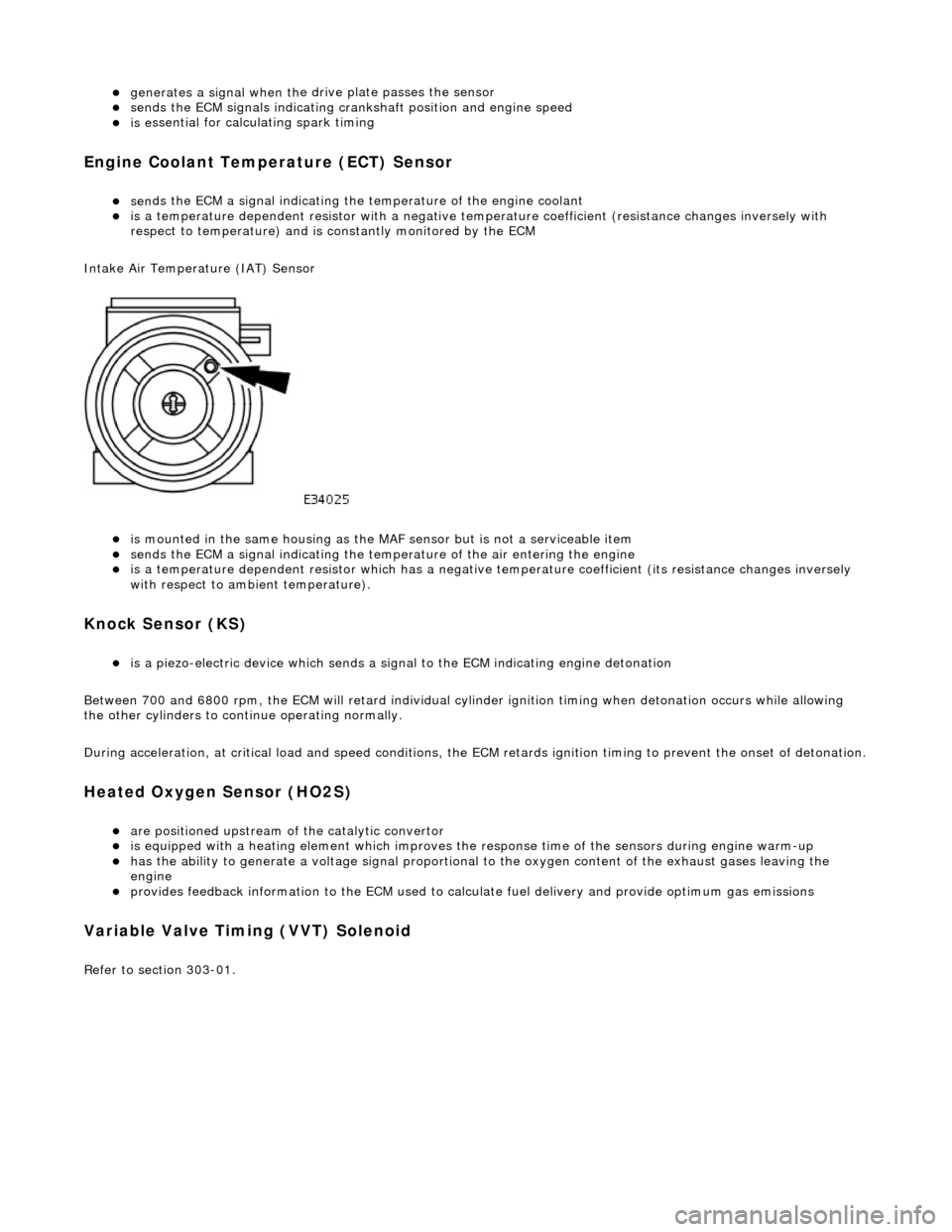
Intake Air Temperature (IAT) Sensor
is m
ounted in the same housing as the MA
F sensor but is not a serviceable item
sen
ds the ECM a signal indicating the temperature of the air entering the engine
is a t
emperature dependent resistor which has a negative
temperature coefficient (its resistance changes inversely
with respect to ambient temperature).
Knock S
ensor (KS)
is a pi
ezo-electric device which sends a signal
to the ECM indicating engine detonation
Between 700 and 6800 rpm, the ECM will retard individual cylinder ignition timing when detonation occurs while allowing
the other cylinders to continue operating normally.
During acceleration, at critical load and speed conditions, the ECM retards ignition timing to prevent the onset of detonation.
H
eated Oxygen Sensor (HO2S)
are
positioned upstream of the catalytic convertor
is equipped with
a heating element wh
ich improves the response time of the sensors during engine warm-up
h
as the ability to generate a voltage signal proportional to the oxygen content of the exhaust gases leaving the
engine
pr
ovides feedback information to the ECM used to calc
ulate fuel delivery and provide optimum gas emissions
Variable V
alve Timing (VVT) Solenoid
R
efer to section 303-01.
Page 1258 of 2490
El
ectronic Engine Controls - Variable
Camshaft Timing (VCT) Oil Control
Solenoid
Re mo
val and Installation
Remova
l
1.
Op
en the engine compartment and fit paintwork protection
sheets.
2. Disc
onnect the batt
ery ground cable.
Re
move the battery cover.
3. Disc
onnect the VVT solenoid connector.
4. Re
move the two bolts which secure the VVT solenoid to the
timing cover.
5. Pull the VVT solenoid clear and discard the O-ring.