Page 896 of 2490
Engine - Engine
Removal
Removal
Special Tool(s)
Engine Lifting Brackets
303-536
Quick Fit Connector Release Tool
310-044
Quick Fit Connector Release Tool
310-054
Quick Fit Connector Release Tool
303-623
Fuel Injection Pressure Test Equipment
310-058
1. Park the vehicle on a four post ramp, over which, an overhead
lifting crane is available, and set the gear selector to 'N'.
The crane should be rated at a minimum of 500 kg Safe
Working Load and have suffici ent fore and aft movement
to traverse the engine assemb ly clear of the vehicle.
Do not apply the handbrake, but use wedges to chock one
wheel to prevent movement of the vehicle.
2. Open the engine compartment and fit paintwork protection
sheets.
3. Disconnect the batt ery ground cable.
Remove the battery cover.
Page 1855 of 2490

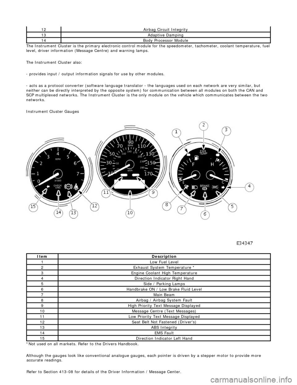
The In
strument Cluster is the primary electronic control module for the speedomete
r, tachometer, coolant temperature, fuel
level, driver information (Message Centre) and warning lamps.
The Instrument Cluster also:
- provides input / output informatio n signals for use by other modules.
- acts as a protocol converter (software language translator - the languages used on each network are very similar, but
neither can be directly interp reted by the opposite system) for communication between all modules on both the CAN and
SCP multiplexed networks. The Instrument Cluster is the only module on the vehicle which communicates between the two
networks.
Instrument Cluster Gauges
*Not used on all markets. Refer to the Drivers Handbook.
Although the gauges look like conventional analogue gauges, each pointer is driven by a stepper motor to provide more
12Ai
rbag Circuit Integrity
13Adaptive Damping
14Body Processor
Module
It
em
De
scription
1Low Fu
el Level
2Exhaus
t System Temperature *
3E
ngine Coolant High Temperature
4Di
rection Indicator Right Hand
5Side
/ Parking Lamps
6Handbrake ON / Low
Bra
ke Fluid Level
7Main
Beam
8Ai
rbag / Airbag System Fault
9Hi
gh Priority Text
Message Displayed
10M
essage Centre (Text Messages)
11Low Pri
ority Text Message Displayed
12Se
at Belt Not Fa
stened (Driver's)
13ABS Integrity
14EMS Fault
15D
irection Indicator Left Hand
accu
rate readings.
Refer to Section 413-08 for details of the Driver Information / Message Center.
Page 2064 of 2490
Installation
16. Remove handbrake trim finisher. Refer to 76.13.63.
17. Move gear selector to position'R'.
18. Slacken and remove nut securing gear selector inner cable to
'J' gate stud.
19. Slacken gear selector outer cable adjustme nt nut at front of
support bracket.
20. Release cable from'J' gate an d position to pemit carpet
withdrawal.
21. With assistance lift and remove carpet, exercising care to
avoid damaging adjacent fittings.
1. With assistance, position carpet in vehicle ensuring that seat
harness and handbrake lever are correctly positioned in
apertures.
Page 2065 of 2490

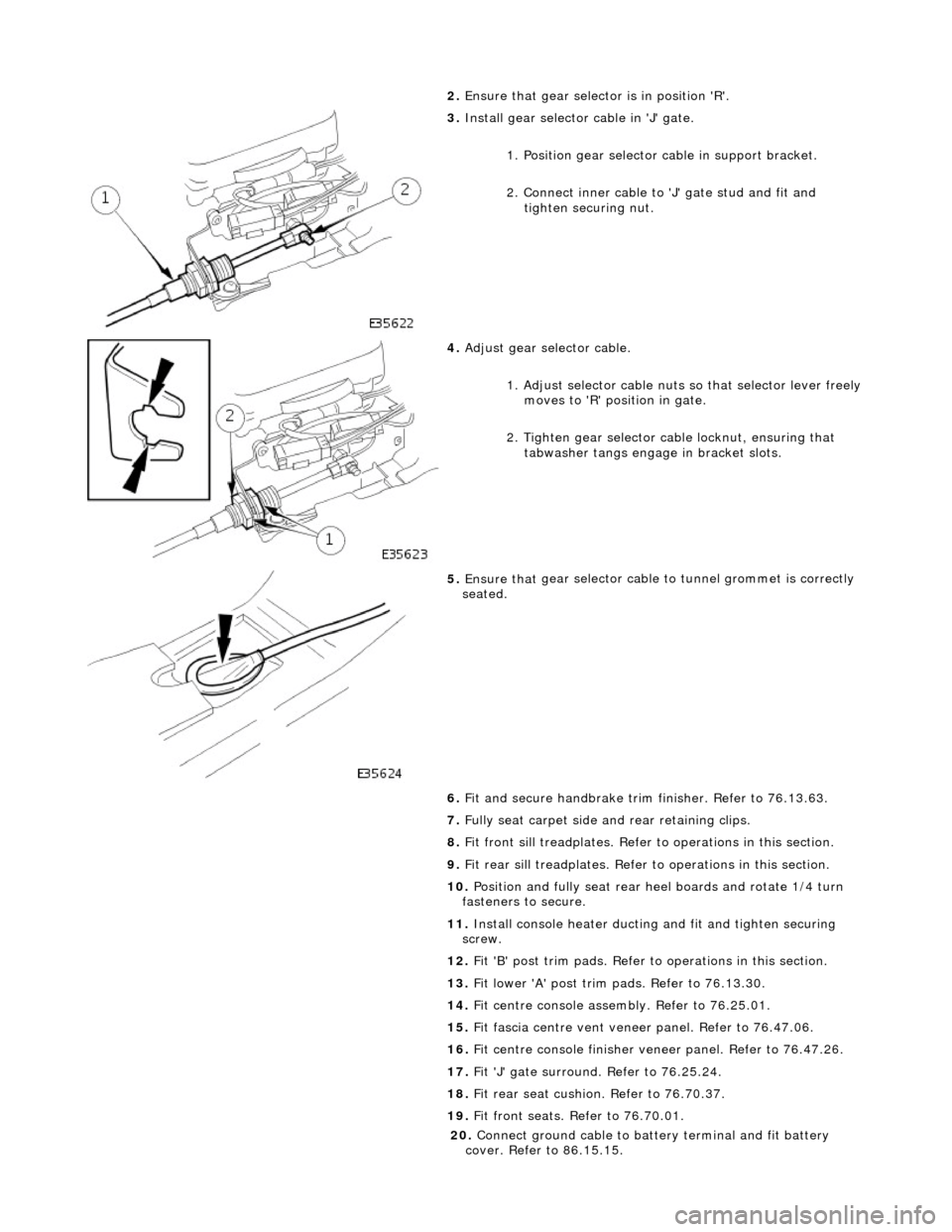
2. Ensure that
gear selector is in position 'R'.
3. Inst
all gear selector cable in 'J' gate.
1. Position gear selector cable in support bracket.
2. Connect inner cable to 'J' gate stud and fit and
tighten securing nut.
4. Adjust
gear selector cable.
1. Adjust selector cable nuts so that selector lever freely
moves to 'R' position in gate.
2. Tighten gear selector ca ble locknut, ensuring that
tabwasher tangs engage in bracket slots.
5. Ensure that
gear selector cable
to tunnel grommet is correctly
seated.
6. Fit and secure handbrake trim finisher. Refer to 76.13.63.
7. Fully seat carpet side and rear retaining clips.
8. Fit front sill treadplates. Refer to operations in this section.
9. Fit rear sill treadplates. Refer to operations in this section.
10. Position and fully seat rear heel boards and rotate 1/4 turn
fasteners to secure.
11. Install console heater ducting and fit and tighten securing
screw.
12. Fit 'B' post trim pads. Refer to operations in this section.
13. Fit lower 'A' post trim pads. Refer to 76.13.30.
14. Fit centre console asse mbly. Refer to 76.25.01.
15. Fit fascia centre ve nt veneer panel. Refer to 76.47.06.
16. Fit centre console finisher vene er panel. Refer to 76.47.26.
17. Fit 'J' gate surround. Refer to 76.25.24.
18. Fit rear seat cushion. Refer to 76.70.37.
19. Fit front seats. Refer to 76.70.01.
20
.
Connect ground cable to batt ery terminal and fit battery
cover. Refer to 86.15.15.
Page 2229 of 2490
Instrument Panel and Console - Floor Console Finish Panel
Removal and Installation
Removal
1. Apply handbrake and turn ignition key to II.
2. Depress brake pedal, move gear selector to position N and turn
ignition key to O.
3. Remove battery cover and di sconnect cable from earth
terminal. Refer to Section 86.15.19.
4. Remove 'J 'gate finisher. Refer to 76.25.24.
5. Slacken and remove the two nuts and two screws securing
the retaining panel.
6. Position retaining panel for access, disconnect SPORT mode
and cruise control ON/OFF swit ch multiplugs and remove
retaining panel complete with switches.
7. Remove and discard bushes from retaining plate.
8. Carefully withdraw veneer pane l, releasing front locating
tongue from upper slot in comsole.
Page 2387 of 2490
Key to Plan
Standard Wheelbase Body Dimensions- Side View
KeyLocation
1Front face body-bumper strut/mounting point
2Rearmost hole, vee-mount to crush tube
3Front Master Datum Plan, centre li ne of front crossmember rear mount ing at main floor RH longitudinal
4Rearmost hole, transmission mounting at main floor RH longitudinal
5Handbrake rear lever bracket fixings
6Rear Master Datum Plan, rear longitudinal
7Tapped boss, rear suspension 'A' frame mounting bush
8Rear suspension spring-pan damper mounting
9Rear suspension differential strut mounting
10Rear face body-bumper strut/mounting point
11Driveshaft centre bearing mounting
Page 2388 of 2490
Key to SideView
Long Wheelbase Body Dimensions-Plan
KeyLocation
1Front face body-bumper strut/mounting point
2Front Master Datum Vertical, centre line of front crossmember rear mounting
3Transmission mountings at the main floor longitudinal
4Handbrake rear lever bracket fixings
5Rear Master Datum Vertical,, rear longitudinal
6Tapped boss, rear suspensi on 'A' frame mounting bush
7Rear suspension spring-pan damper mounting
8Rear suspension differential strut mounting
9Rear face body-bumper strut/mounting point
10Wheel centre to bumper cover face
11Wheelbase
12Wheel Centre to Bumper Cover Face
13Driveshaft centre bearing mounting
Page 2389 of 2490
Key to Plan
Long Wheelbase Body Dimensions- Side View
KeyLocation
1Front face body-bumper strut/mounting point
2Rearmost hole, vee-mount to crush tube
3Front Master Datum Plan, centre line of front crossmember rear mount ing at main floor RH longitudinal
4Rearmost hole, transmission mounting at main floor RH longitudinal
5Handbrake rear lever bracket fixings
6Rear Master Datum Plan, rear longitudinal
7Tapped boss, rear suspension 'A' frame mounting bush
8Rear suspension spring-pan damper mounting
9Rear suspension differential strut mounting
10Rear face body-bumper strut/mounting point
11Driveshaft centre bearing mounting