Page 2138 of 2490

Seating - Front Seat Cushion Heater Mat
Removal and Installation
Removal
Installation
1. WARNING: FOLLOWING DISCONNECTION OF THE
BATTERY A PERIOD OF AT LEAST ONE MINUTE MUST BE
ALLOWED TO ELAPSE BEFORE WORKING ON A FRONT SEAT WITH
A SIDE AIRBAG FITTED.
Remove battery cover and disc onnect ground cable from
battery. Refer to 86.15.19.
2. Remove front seat from vehicle. Refer to 76.70.01
3. Remove seat back fini sher. Refer to 76.70.09.
4. Remove seat cushion cover as sembly. Refer to 76.70.33.
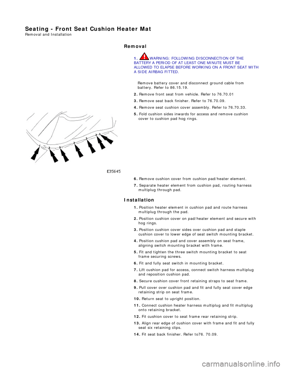
5. Fold cushion sides inwards for access and remove cushion
cover to cushion pad hog rings.
6. Remove cushion cover from cushion pad/heater element.
7. Separate heater element from cushion pad, routing harness
multiplug through pad.
1. Position heater element in cushion pad and route harness
multiplug through the pad.
2. Position cushion cover on pad/heater element and secure with
hog rings.
3. Position cushion cover sides over cushion pad and staple
cushion cover to lower edge of seat switch mounting bracket.
4. Position cushion pad and cover assembly on seat frame,
aligning switch mounting bracket with frame.
5. Fit and tighten the three switch mounting bracket to seat
frame securing screws.
6. Fit and fully seat switch in mounting bracket.
7. Lift cushion pad for access, connect switch harness multiplug
and reposition cushion pad.
8. Secure cushion cover front retaining straps to seat frame.
9. Pull cover over cushion pad and fit and fully seat cover edge
retaining strip on seat frame.
10. Return seat to upright position.
11. Connect cushion heater harnes s multiplug and fit multiplug
onto retaining bracket.
12. Fit cushion cover to seat fra me rear retaining strip.
13. Align rear edge of cushion cover with frame and fit and fully
seat six retaining clips.
14. Fit seat back finisher. Refer to76. 70.09.
Page 2144 of 2490
Seating - Front Seat Recliner Motor
Removal and Installation
Removal
1. WARNING: FOLLOWING DISCONNECTION OF THE
BATTERY A PERIOD OF AT LEAST ONE MINUTE MUST BE
ALLOWED TO ELAPSE BEFORE WORKING ON A FRONT SEAT WITH
A SIDE AIRBAG FITTED.
Remove battery cover and disc onnect ground cable from
battery terminal. Refer to 86,.15.19.
2. Remove front seat and position for access. Refer to 76.70.01.
3. Remove front seat back finisher. Refer to 76.70.09.
4. Release seat squab cover securing clips from frame.
5. Release seat squab cover lower edge retaining strip from
frame.
6. Disconnect recline motor/potentiometer harness multiplug
(white).
7. Remove and discard gearbox RH drive shaft end securing clip.
Page 2147 of 2490
Seating - Front Seat Track
Removal and Installation
Removal
1. WARNING: FOLLOWING DISCONNECTION OF THE
BATTERY A PERIOD OF AT LEAST ONE MINUTE MUST BE
ALLOWED TO ELAPSE BEFORE WORKING ON A FRONT SEAT WITH
A SIDE AIRBAG FITTED.
Remove battery cover and disc onnect ground cable from
battery terminal. Refer to 86,.15.19.
2. Remove front seat from vehicle. Refer to 76.70.01.
3. Invert seat for access.
4. Slacken and remove LH slide se curing bolts and remove seat
belt anchor mounting bracket.
5. Slacken and remove RH slide se curing bolts and remove seat
belt buckle moun ting bracket.
6. Disconnect seat cushion tilt motor drive cables.
7. Remove slide assembly.
1. Position slide/motor assembly for access and release seat harness securing clips.
2. Drill out pop rivets securing slide to motor frame.
Page 2149 of 2490
Seating - Front Seat Track Motor
Removal and Installation
Removal
1. WARNING: FOLLOWING DISCONNECTION OF THE
BATTERY A PERIOD OF AT LEAST ONE MINUTE MUST BE
ALLOWED TO ELAPSE BEFORE WORKING ON A FRONT SEAT WITH
A SIDE AIRBAG FITTED.
Remove battery cover and disc onnect ground cable from
battery terminal. Refer to 86.15.19.
2. Remove front seat from vehicle and place inverted on clean
work surface. Re fer to 76.70.01.
3. Release rearward (RH) tilt motor harness multiplug from
retaining bracket and di sconnect multiplug.
4. Release forward (LH) tilt motor harness multiplug from
retaining bracket and di sconnect multiplug.
5. Disconnect seat control module harness multiplugs.
6. Release heater relay (brown ) from retaining bracket.
Page 2201 of 2490

Installation
the spray bottle with water and mix.
5. Apply cutting lubricant to the rear quarter window glass
adhesive.
6. Install the cutting tool blade BTB-WK4ZS to the cutting tool
BTB-WK10HD.
7. WARNING: When removing the rear quarter window
glass, personal protec tion must be worn. Failure to follow this
instruction may result in personal injury.
• NOTE: Apply cutting lubricant to the cutting tool frequently
through out the cutting process.
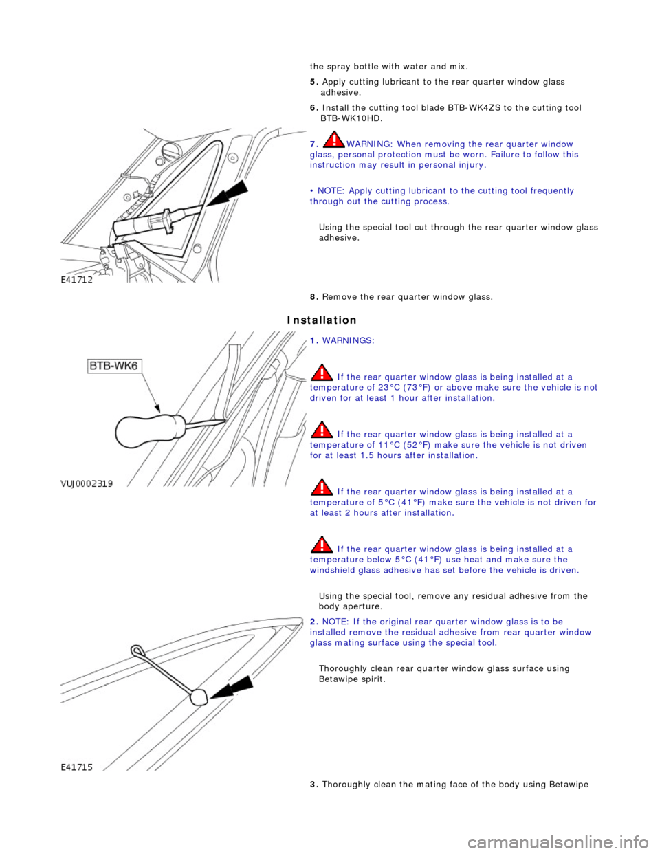
Using the special tool cut throug h the rear quarter window glass
adhesive.
8. Remove the rear quarter window glass.
1. WARNINGS:
If the rear quarter window glass is being installed at a
temperature of 23°C (73°F) or abov e make sure the vehicle is not
driven for at least 1 hour after installation.
If the rear quarter window glass is being installed at a
temperature of 11°C (52°F) make sure the vehicle is not driven
for at least 1.5 hours after installation.
If the rear quarter window glass is being installed at a
temperature of 5°C (41°F) make su re the vehicle is not driven for
at least 2 hours after installation.
If the rear quarter window glass is being installed at a
temperature below 5°C (41°F) use heat and make sure the
windshield glass adhesive has set before the vehicle is driven.
Using the special tool, remove any residual adhe sive from the
body aperture.
2. NOTE: If the original rear qu arter window glass is to be
installed remove the residual ad hesive from rear quarter window
glass mating surface using the special tool.
Thoroughly clean rear quarte r window glass surface using
Betawipe spirit.
3. Thoroughly clean the mating face of the body using Betawipe
Page 2207 of 2490
12. Pass free end of cheese wire through penetration and install
second cutting handle.
13. WARNING: When removing the rear window glass,
personal protection must be worn. Failure to follow this
instruction may result in personal injury.
• CAUTIONS:
Make sure the ch eese wire cannot contact the paintwork
while the the rear window glass ad hesive is being cut. Failure to
follow this instruction may result in damage to the vehicle.
When cutting, do not allow ch eese wire to contact edge of
window glass as this will crack the window glass.
• NOTE: Apply cutting lubricant to the cheese wire frequently
through out the cutting process.
With assistance and exercising care to avoid damaging the
paintwork, cut around the re ar window glass commencing
upwards and along the top.
14. Install the lifting handles to the windshield glass, and with
assistance carefully remove th e rear window glass from the
vehicle.
Page 2208 of 2490

Installation
15. Remove the lifting handles from the rear window glass.
16. Remove cheese wire cutting tool from the vehicle, separate
handles by moving centre tubes upwards and discard cheese
wire.
1. WARNINGS:
If the rear window glass is being installed at a temperature
of 23°C (73°F) or above make sure the vehicle is not driven for at
least 1 hour after installation.
If the rear window glass is being installed at a temperature
of 11°C (52°F) make sure the vehicl e is not driven for at least 1.5
hours after installation.
If the rear window glass is being installed at a temperature
of 5°C (41°F) make su re the vehicle is not driven for at least 2
hours after installation.
If the rear window glass is being installed at a temperature
below 5°C (41°F) use heat and ma ke sure the rear window glass
adhesive has set before the vehicle is driven.
• NOTE: To aid bonding of a new re ar window glass, make sure at
least 1 mm (0.04 in) of residual adhesive remains on the body
flange.
• NOTE: If the original rear window glass is to be installed remove
the residual adhesive from rear window glass mating surface
using a suitable scraper.
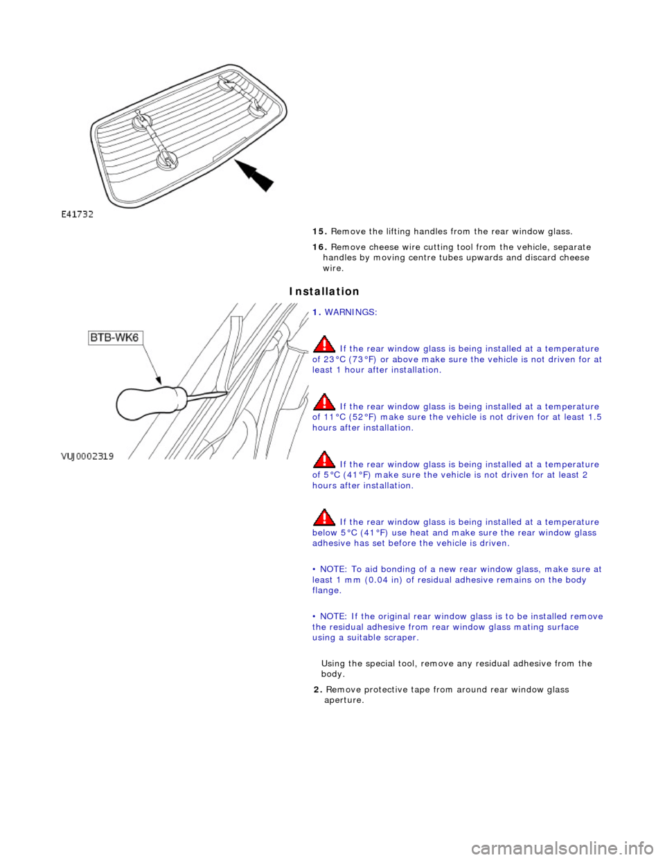
Using the special tool, remove any residual adhe sive from the
body.
2. Remove protective tape from around rear window glass
aperture.
Page 2214 of 2490

Cut a suitable length of cheese wire and pass one end
through handle tube and locating aperture.
Move cutting handle central tube downwards to secure
cheese wire.
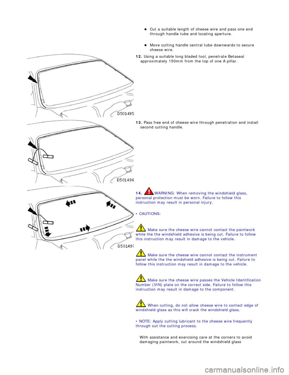
12. Using a suitable long bladed tool, penetrate Betaseal
approximately 150mm from the top of one A pillar.
13. Pass free end of cheese wire through penetration and install
second cutting handle.
14. WARNING: When removing the windshield glass,
personal protection must be worn. Failure to follow this
instruction may result in personal injury.
• CAUTIONS:
Make sure the ch eese wire cannot contact the paintwork
while the the windshield adhesive is being cut. Failure to follow
this instruction may result in damage to the vehicle.
Make sure the cheese wire cannot contact the instrument
panel while the the windshield adhesive is being cut. Failure to
follow this instruction may result in damage to the vehicle.
Make sure the cheese wire passes the Vehicle Identification
Number (VIN) plate on the correct side. Failure to follow this
instruction may result in damage to the component.
When cutting, do not allow ch eese wire to contact edge of
windshield glass as this will crack the windshield glass.
• NOTE: Apply cutting lubricant to the cheese wire frequently
through out the cutting process.
With assistance and exercising care at the corners to avoid
damaging paintwork, cut around the windshield glass