1998 JAGUAR X308 warning
[x] Cancel search: warningPage 1691 of 2490
Fuel System - Gener
al Information - Fuel Tank Draining
Gen
eral Procedures
1.
WARNING: BEFORE PROCEEDING, IT IS ESSENTIAL THAT
THE WARNING NOTES GIVEN IN SECTION 100-00 (UNDER THE
HEADING 'SAFETY PRECAUTIONS') ARE READ AND
UNDERSTOOD.
Remove the battery. Refer to operation 86.15.01.
2. De
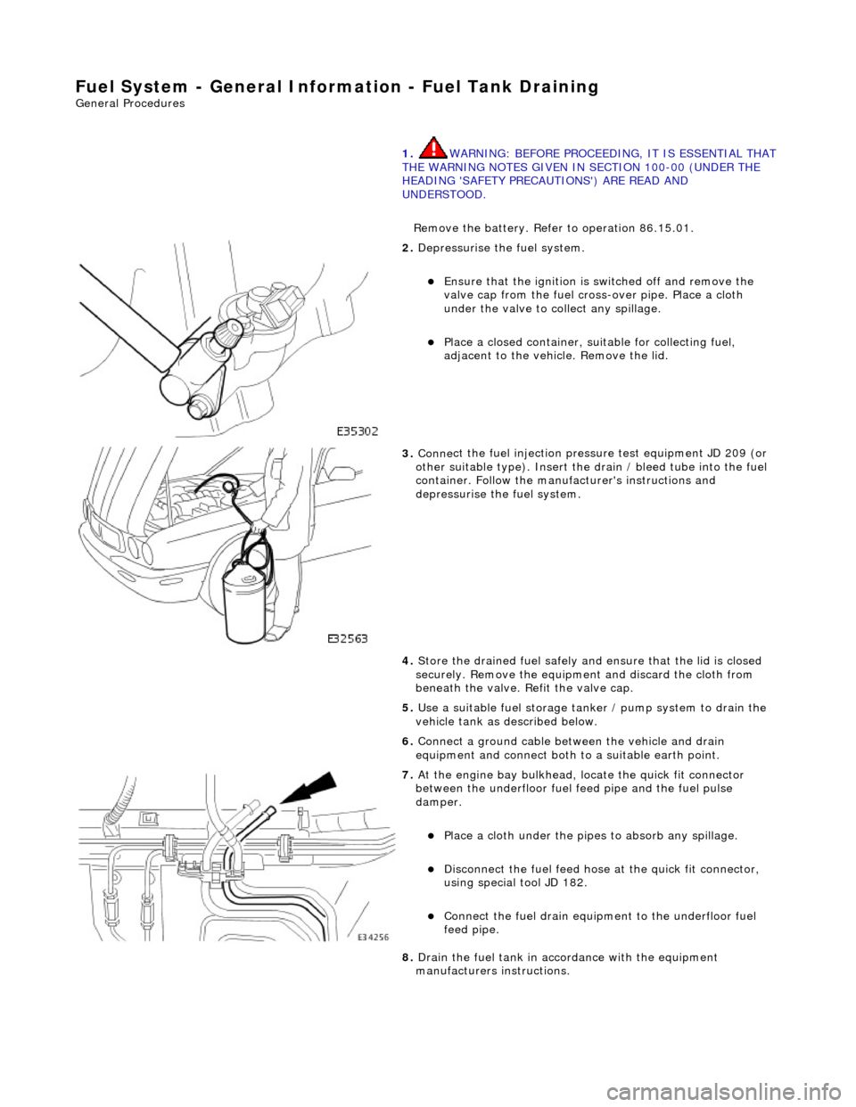
pressurise the fuel system.
E
nsure that the ignition is
switched off and remove the
valve cap from the fuel cross-over pipe. Place a cloth
under the valve to collect any spillage.
Pla
ce a closed container, su
itable for collecting fuel,
adjacent to the vehicle. Remove the lid.
3. Conne
ct the fuel injection pressu
re test equipment JD 209 (or
other suitable type). Insert the drain / bleed tube into the fuel
container. Follow the manufa cturer's instructions and
depressurise the fuel system.
4. Store the drained fuel safely and ensure that the lid is closed
securely. Remove the equipmen t and discard the cloth from
beneath the valve. Refit the valve cap.
5. Use a suitable fuel storage tank er / pump system to drain the
vehicle tank as described below.
6. Connect a ground cable betw een the vehicle and drain
equipment and connect both to a suitable earth point.
7. At the engine bay bulkhead, lo cate the quick fit connecto
r
between the underfloor fuel feed pipe and the fuel pulse
damper.
Pla
ce a cloth under the pipes
to absorb any spillage.
D
isconnect the fuel feed hose
at the quick fit connector,
using special tool JD 182.
Conne
ct the fuel drain equipment to the underfloor fuel
feed pipe.
8. Drain the fuel tank in accordance with the equipment
manufacturers instructions.
Page 1732 of 2490
Fu
el Tank and Lines - Fuel Level Sensor
Remov
a
l and Installation
Removal
Ins
tallation
1.
WA
RNING: BEFORE PROCEEDING, IT IS ESSENTIAL THAT THE
WARNING NOTES GIVEN IN SECTIO N 100-00 (UNDER THE HEADING
'SAFETY PRECAUTIONS') ARE READ AND UNDERSTOOD.
Remove the battery. For additional information, refer to Section 414
-01
Battery, Mounting and Cables
.
2.
Drain
the fuel tank using a suitable suction pump/tanker. If the On-
board Refueling Vapour Recovery (ORVR) system is fitted, refer to
Section 310
-00 Fu
el System
- Gen
e
ral Information
.
3. Remov
e the trunk front liner. For additional information, refer to
Section 501
-05 Interior Trim
and Ornamentation
.
4. D
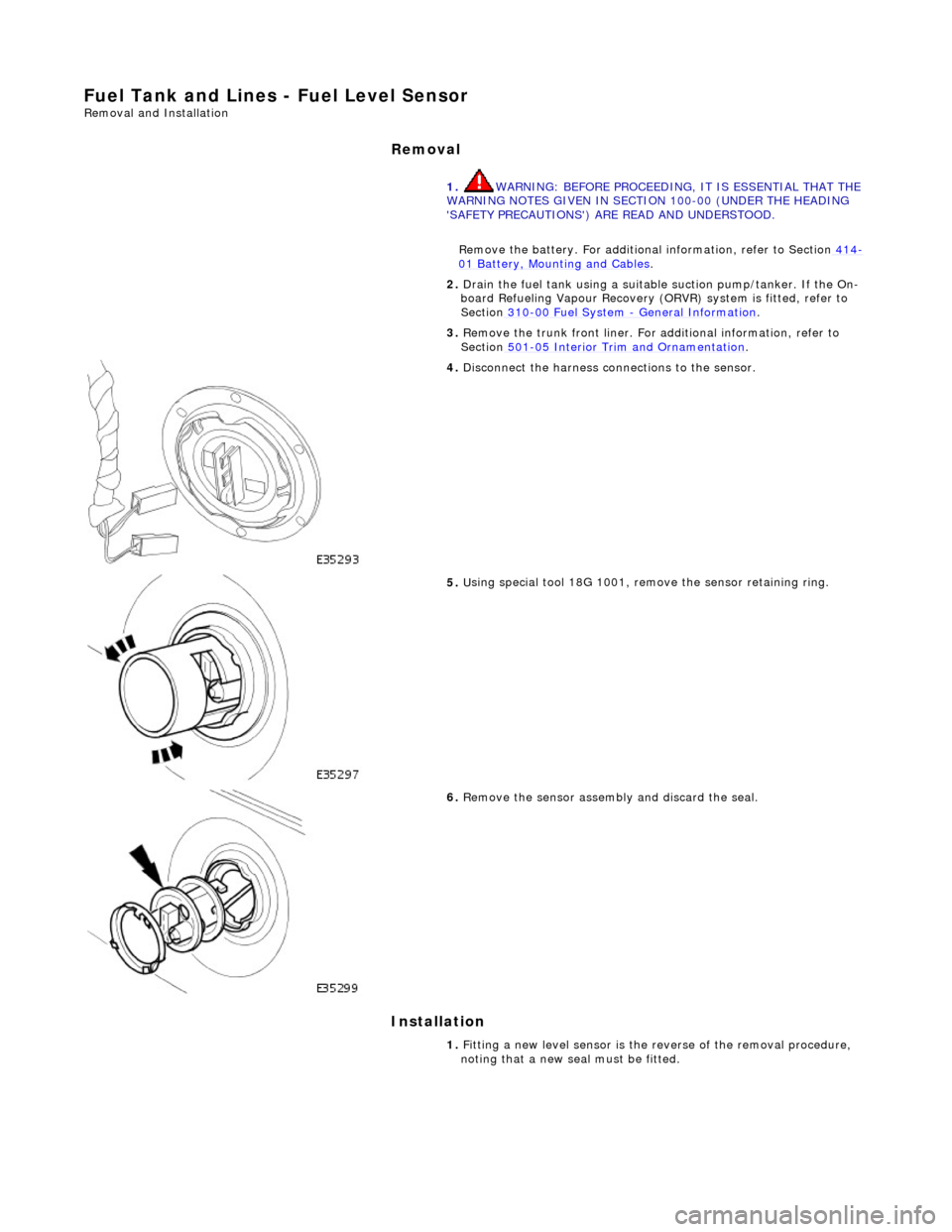
isconnect the harness co
nnections to the sensor.
5. U
sing special tool 18G 1001, remo
ve the sensor retaining ring.
6.
Remov
e the sensor assembly and discard the seal.
1. Fitting a new level sensor is the reverse of the removal procedure,
noting that a new seal must be fitted.
Page 1733 of 2490
Fuel Tank and Li
nes - Fuel Pump
Re
moval and Installation
Remov
al
Installation
1.
WARNING: B
EFORE PROCEEDING, IT IS ESSENTIAL THAT
THE WARNING NOTES GIVEN IN SECTION 100-00 (UNDER THE
HEADING 'SAFETY PRECAUTIONS') ARE READ AND
UNDERSTOOD.
Remove the battery. For additional information, refer to Section
414
-0
1 Battery, Mounting and Cables
.
2.
Drain th
e fuel tank using a suitab
le suction pump/tanker. If the
On-board Refueling Vapour Recove ry (ORVR) system is fitted,
refer to Section 310
-00
Fuel System
- General
Information
.
3. R
emove the fuel tank. For addi
tional information, refer to Fuel
Tank
in this section.
4. Remove the fuel tank evaporativ e loss flange sealing ring. For
additional information, refer to Section 303
-13
.
5. R
emove fuel feed hose from tank.
U
sing special tool JD175, slacken fuel feed hose to tank
stub securing clip.
Di
sconnect hose from tank stub.
6. Remove fuel pump assembly.
R
elease bolt securing fuel
pump mounting bracket and
place assembly to front.
Slac
ken securing clip and disc
onnect hose from fuel pump.
R
emove link lead from fuel pump.
Re
move pump.
1. NOTE: Install new sealing ring to evaporative loss flange. For
additional information, refer to Section 303
-13
.
In
stallation is th
e reverse of the removal procedure.
Page 1734 of 2490
Fuel Tank and Lines - Fuel Tank
Re
mo
val and Installation
Remov
a
l
•
NO
TE: This removal/installation procedure is applicable to all tank assembly variants.
S
p
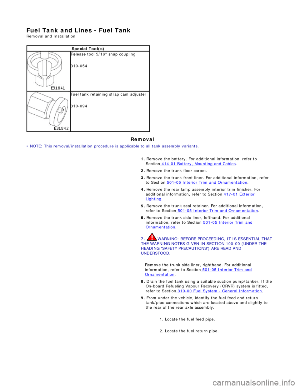
ecial Tool(s)
R
e
lease tool 5/16" snap coupling
310-054
F u
el tank retaining strap cam adjuster
310-094
1. Remove the battery. For additi onal information, refer to
Section 414
-01
Battery, Mounting and Cables
.
2. Re
move the trunk floor carpet.
3. Remove the trunk front liner. Fo r additional information, refer
to Section 501
-05
Interior Trim and Ornamentation
.
4. Re
move the rear lamp assembly interior trim finisher. For
additional information, refer to Section 417
-01
Exterior
Ligh
ting.
5. Re
move the trunk seal retainer
. For additional information,
refer to Section 501
-0 5
Interior Trim and Ornamentation
.
6. Re
move the trunk side liner, lefthand. For additional
information, refer to Section 501
-05
Interior Trim and
Or
n
amentation
.
7. WARNING: B E
FORE PROCEEDING, IT IS ESSENTIAL THAT
THE WARNING NOTES GIVEN IN SECTION 100-00 (UNDER THE
HEADING 'SAFETY PRECAUTIONS') ARE READ AND
UNDERSTOOD.
Remove the trunk side liner, righthand. For additional
information, refer to Section 501
-05
Interior Trim and
Or
n
amentation
.
8.
Drain th e fue
l tank using a suitab
le suction pump/tanker. If the
On-board Refueling Vapour Recove ry (ORVR) system is fitted,
refer to Section 310
-00 Fu
el System
- General
Information
.
9. Fr
om under the vehicle, identify the fuel feed and return
tank/pipe connections which are located above and slightly to
the rear of the rear axle assembly.
1. Locate the fuel feed pipe.
2. Locate the fuel return pipe.
Page 1754 of 2490
WARNING: NEVER USE A CFC 12 ANALYZ
ER OR NAKED FLAME TYPE.
Leak tests should be carried out with a UV spot lamp or an electronic analyzer which is dedicated to HFC 134A refrigerant.
Handling Lubricati
ng Oil
Av
oid breathing lubricant mist; it can cau
s
e irritation to the respiratory system.
Always use fresh oil from a sealed containe r and do not leave oil exposed to the atmosphere for any reason other than to fill
or empty a system. PAG oil is very hygr oscopic (absorbs water) and will rapidly become contaminated by atmospheric
moisture.
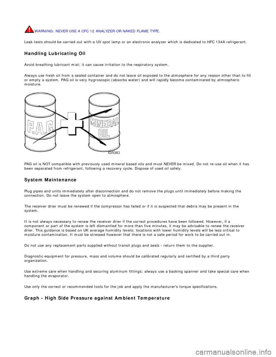
PAG oil is NOT compatible with previously used mineral based oi ls and must NEVER be mixed. Do not re-use oil when it has
been separated from refrigerant, following a re covery cycle. Dispose of used oil safely.
System Maintenance
Plug pipes an
d units immediatel
y after disconnection an d do not remove the plugs until immediately before making the
connection. Do not leave the system open to atmosphere.
The receiver drier must be renewed if the compressor has failed or if it is susp ected that debris may be present in the
system.
It is not always necessary to renew th e receiver drier if the correct procedur es have been followed. However, if a
component or part of the system is left dismantled for more than five minutes, it may be advisable to renew the receiver
drier. This guidance is based on UK average humidity levels; lo cations with lower humidity levels will be less critical to
moisture contamination. It must be stressed however th at there is not a safe period for work to be carried out in.
Do not use any replacement parts su pplied without transit plugs and seals - return them to the supplier.
Diagnostic equipment for pres sure, mass and volume should be calibrated regularly and certified by a third party
organization.
Use extreme care when handling and securi ng aluminum fittings; always use a backing spanner and take special care when
handling the evaporator.
Use only the correct or re commended tools for the job and apply the manufacturer's torque specifications.
Graph - High S
ide Pressure against Ambient Temperature
Page 1761 of 2490
Climate Co
ntrol System - General In
formation - Air Conditioning (A/C)
System Check - Re tail Procedure
Gen
eral Procedures
E
vacuating the Manifold Gauge Set
Connecting the Manifold Gauge Set
C
AUTION: Only use hoses with connectors wh
ich are dedicated to HFC 134A charge ports.
Stabilizing the System
1.
At
tach the center (service) hose to a vacuum pump and start
the pump. Open fully both high and low valves and allow the
vacuum to remove air and mois ture from the manifold set for
at least five minutes.
CAUTION: It is imperative th at the vacuum pump is not
subjected to a positi ve pressure of any degree. Therefore the
pump must be fitted wi th an isolation valve at the center (service
hose) connection and this valve mu st be closed before the pump
is switched off. This operation replaces the 'purge' procedure used
on previous systems. Observe the manufacturer's
recommendation with regard to vacuum pump oil changes.
Turn the vacuum pump off and isol ate it from the center service
hose but do not open the hose to atmosphere.
1. Att
achment of the hose quick release connectors to the high
and low side system ports is stra ightforward, provided that the
high and low valves are closed and the system is NOT
operational.
WARNING: UNDER NO CIRCUMSTANCES SHOULD THE
CONNECTIONS BE MADE WITH THE SYSTEM IN OPERATION OR
THE VALVES OPEN. SHOULD THE VALVES BE OPEN AND A
VACUUM PUMP OR REFRIGERANT CONTAINER ATTACHED, AN
EXPLOSION COULD OCCUR AS A RESULT OF HIGH PRESSURE
REFRIGERANT BEING FORCED BACK INTO THE VACUUM PUMP OR
CONTAINER.
Assessment of system operating efficiency and fault
classification may be achieved by using the facilities on your
Recovery / Recharging / Recycling station, follow the
manufacturer's instructions implicitly and observe all safety
considerations.
1. Accurate test gauge data wi
ll on
ly be attained if the system
temperatures and pressures are stabilized.
E
nsure that equipment and hoses cannot come into
contact with engine moving parts or sources of heat.
It is recommended th at a free standing air
mover is placed
in front of the vehicle to provide air flow through the
condenser / cooling system.
St
art the engine, allow it to attain normal working
temperature and set at fast idle (typically 1200 to 1500
rpm).
Select full
air condit
ioning performance.
With
all temperatures and pres
sures stable, or displaying
symptoms of faults; begin relevant test procedures.
Page 1768 of 2490
Climate Control System - General Infor
mation - Refrigerant System Tests
Gen
e
ral Procedures
WARNING: USE EXTREME CARE AND OBSERVE ALL SAFETY PRECAUTIONS RELATED TO THE USE OF REFRIGERANTS.
FAILURE TO FOLLOW THIS INSTRUCTION MAY RESULT IN PERSONAL INJURY.
CAUTION: The A/C refrigerant analyzer mu st be used before the recovery of any vehicle' s A/C refrigerant. Failure to
do so puts workshop bulk refrigerant at risk of contamination. If the vehicle A/C refrigerant is contaminated, refer the
customer to return to the repair facility that carried out the last A/C repair. If the customer wishes to pay the additional
cost, use the A/C recovery equipment that is designated for recovering contaminated A/C refrige rant. All contaminated A/C
refrigerant must be disposed of as hazardous waste. To prevent possible pe rsonal injury, for all equipment, follow the
equipment manufacturer's procedures and instructions.
• NOTE: Jaguar Cars Ltd. supports the effi cient usage, recovery and recycling of the refrigera nt used in passenger car air
conditioners. Jaguar Cars Ltd. recommend s the use of UL-approved recovery/recycling equipment during any A/C system
repair and recharge procedure which requ ires that the system be evacuated.
1. Us
e UL-approved recovery/recycling equipment to evacuate
and recover the A/C system.
Follow t h
e equipment manufacturer's procedures and
instructions for use of equipment.
Page 1848 of 2490
Control Components - Remote Climate Control ModuleRHD RWD
Removal and Installation
Removal
1. Position the driver's seat fully rearward
2. Position the steering column DOWN and fully EXTENDED
3. Disconnect the battery ground lead
4. Lower steering column cowl 76.46.03
5. Upper steering column cowl 76.46.02
6. Knee bolster, driver's side 76.46.11
7. Position the steering in the 'straight ahead'
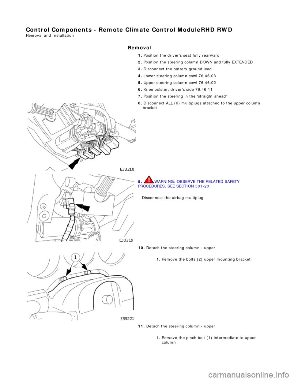
8. Disconnect ALL (6) multiplugs attached to the upper column
bracket
9. WARNING: OBSERVE THE RELATED SAFETY
PROCEDURES, SEE SECTION 501-20
Disconnect the airbag multiplug
10. Detach the steering column - upper
1. Remove the bolts (2 ) upper mounting bracket
11. Detach the steering column - upper
1. Remove the pinch bolt (1) intermediate to upper column