Page 1159 of 2490

T
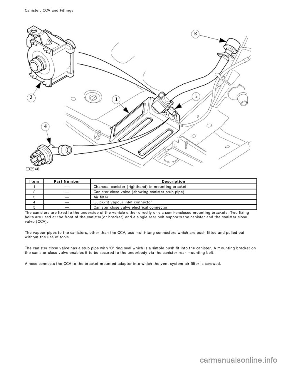
he canisters are fixed to the underside of the vehicle either
directly or via semi-enclosed mounting brackets. Two fixing
bolts are used at the front of the canister(or bracket) and a single rear bolt supports the canister and the canister close
valve (CCV).
The vapour pipes to the canisters, other than the CCV, use multi-tang connectors which are push fitted and pulled out
without the use of tools.
The canister close valve has a stub pipe with 'O' ring seal wh ich is a simple push fit into the canister. A mounting bracket on
the canister close valve enables it to be secured to the underbody via the canister rear mounting bolt.
A hose connects the CCV to the bracket mounted adaptor into which the vent system air filter is screwed.
It
em
Par
t Number
De
scription
1—C
harcoal canister (righthand) in mounting bracket
2—Cani
ster close valve (showi
ng canister stub pipe)
3—Ai
r filter
4—Q
uick-fit vapour inlet connector
5—Cani
ster close valve electrical connector
Canister, CCV an
d Fittings
Page 1160 of 2490
Ite
m
Part
Number
Descr
iption
1—Fu
el tank pressure sensor (if applicable)
2—Engine m
anagement ECU
3—EVAP canister purge va
lve
4—EVAP ca
nister close valve (if applicable)
5—Engine
mana
gement fusebox - IGN supply
Circuit diagram
,
evaporative emissions systems
Page 1161 of 2490

E
vaporative Emissions - Evaporative Emissions
D
iagnosis and Testing
Prelim
inary Inspection
1.
1. Vis
ually inspect for obvious signs of mechanical or electrical damage.
V
isual Inspection Chart
2.
2. If
an obvious cause for an observed or
reported concern is found, correct th e cause (if possible) before proceeding
to the next step.
3. 3. If the concern is not visually evident, verify the symptom and proceed with diagnosis, using the Jaguar approved
diagnostic system, where available.
4. 4. Where K-Line or Vacutec equipment is available, it should be used as an aid to diagnosis. The equipment must be
capable of testing to the 0.020 thou standard (2001 MY on).
Diagnostic Drive Cycles
Following th
e setting of a DTC, the appropriate repairs must
be carried out, and the normal operation of the system
checked. This will be done by performing a series of drive cycles which will enable the vehicle to operate the evaporative
emissions system as a function check. For details of the drive cycles,
REFER to Section 303
-1
4 Electronic Engine Controls
.
ECM adapt
ations.
Diagnostic Trouble Code
(D
TC) index/Symptom Chart
1.
1. Wh
ere the Jaguar approved diagnostic sy
stem is available, complete the S93 report before clearing any or all fault
codes from the vehicle.
• NOTE: If a DTC cannot be cleared, then there is a permanent fault present that flag s again as soon as it is cleared. (The
exception to this is P1260, which will only clear following an ignition OFF/ON cycle after rectification).
2. 2. If the cause is not visually evident and the Jaguar approv ed diagnostic system is not available, use a fault code
reader to retrieve the fault codes be fore proceeding to the Diagnostic Trou ble Code (DTC) Index Chart, or the
Symptom Chart if no DTCs are set.
3. 3. Using the Jaguar approved diagnostic system where available, and a scan tool where not, check the freeze frame
data for information on the conditions applicable when the fault was flagged. The format of this will vary,
depending on the tool used, but can pr ovide information useful to the technician in diagnosing the fault.
CAUTION: When probing connectors to take measurements in the course of the pinpoint tests, use the adaptor kit,
part number 3548-1358-00.
• NOTE: When performing electrical voltag e or resistance tests, always use a digital multimeter (DMM) accurate to 3
decimal places, and with an up-t o-date calibration certificate. When testing resistance, always take the resistance of the
DMM leads into account.
• NOTE: Check and rectify basic faults before beginning diagnostic ro utines involving pinpoint tests.
MechanicalElectrical
Engi
ne oil level
Coo
ling system coolant level
Fue
l level
Fuel contaminatio
n
/grade/quality
Throttle body Poly
-vee belt
F
uses
W
iring harness
E
lectrical connector(s)
Sens
or(s)
Engine
control module (ECM)
Page 1177 of 2490

Th
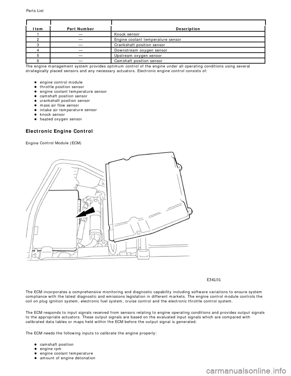
e engine management system provides optimum control of
the engine under all operating conditions using several
strategically placed sensors and any necessary actuators. Electronic engine control consists of:
engine
control module
throttle posi
tion sensor
engi
ne coolant temperature sensor
cam
shaft position sensor
c
rankshaft position sensor
mass air
flow sensor
intake air temper
ature sensor
kn
ock sensor
heat
ed oxygen sensor
Electronic Engine Control
Engine
Control Module (ECM)
The ECM incorporates a comprehensive monitoring and diagnostic capability including software variations to ensure system
compliance with the latest diagnostic and emissions legislation in different markets. The engine control module controls the
coil on plug ignition system, electronic fuel system, cr uise control and the electronic throttle control system.
The ECM responds to input signals received from sensors relating to engine operatin g conditions and provides output signals
to the appropriate actuators. These outp ut signals are based on the evaluated input signals which are compared with
calibrated data tables or maps held within th e ECM before the output signal is generated.
The ECM needs the following inputs to calibrate the engine properly:
cam
shaft position
It
em
Par
t Number
De
scription
1—Knock
sensor
2—Engine
coolant temperature sensor
3—Cranksh
aft position sensor
4—D
ownstream oxygen sensor
5—Upstream oxygen sensor
6—Camshaft position
sensor
P
arts List
engi
ne rpm
engi
ne coolant temperature
amount
of engine detonation
Page 1178 of 2490
Throttle Position (TP) Sensor
Location
P
arts List
sen
d
s the ECM a signal indica
ting throttle plate angle
is
the main input to the ECM from the driver
i
s
a dual Hall effect devi
ce mounted on the motor en d of the throttle body
Two additional sensors are attached to the throttle body to provide additional feedback to the ECM: a mechanical guard
position sensor and an accelerator pedal position sensor.
Cam s
haft Position (CMP) Sensor
sen
d
s the ECM a signal indicating camshaft po
sition for fuel synchronization purposes
is
a variable reluctance device mounted on bank 2 cylinder side face
generates a signal when the ri
ng
fitted to the bank 2 inlet
camshaft passes the sensor
Cranksha
ft Position (CKP) Sensor
i
s
a variable reluctance device
mounted on the engine oil pan
Ite
m
Par
t
Number
De
scr
iption
1—Acce
le
rator pedal and mechanic
al guard position sensors
2—Throttle
(blade)
position sensor
Page 1181 of 2490
P
arts List
It
em
Par
t Number
De
scription
1—PI032
VVT solenoid 2
2—PI027
KS 2
3—PI004
ECT sensor
4—PI026
KS 1
5—PI031
VVT solenoid 1
6—PI035
MAFS (on vehicle)
7—PI050
Generator
8—PI040
Oil pressure switch
9—PI018
to PI021 Bank 1 Ignition coils 1 to 4
PI022 to PI025 Bank 2 Ignition coils 1 to 4
10—PI006
Throttle valve position sensor
11—PI002 En
gine management harness (on vehicle)
12—PI001 En
gine management harness (on vehicle)
13—PI033
Throttle valve motor
14—PI034
EGR valve (where fitted)
15—PI015 CM
P sensor
16—PI042
Accelerator pedal and
mechanical guard sensors
17—PI007
to PI010 Bank 1 Injectors 1 to 4 PI011 to PI014 Bank 2 Injectors 1 to 4
18—PI037
Compressor lock
sensor (where fitted)
19—PI036
Compressor clutch
20—PI017 CK
P sensor
E
ngine Harness Connectors
Location
Page 1182 of 2490
Ite
m
Par
t
Number
De
scr
iption
1—Engine
management fuse box
2—Engine
control module (E
CM)
Circuit Diagrams (extracts only)
ECM Su
pply Voltage
Page 1184 of 2490
Ite
m
Part
Number
Descr
iption
1—Knock
sensors, banks 1 and 2
2—Engine
control module (E
CM)
Knock
Sensor