Page 1150 of 2490
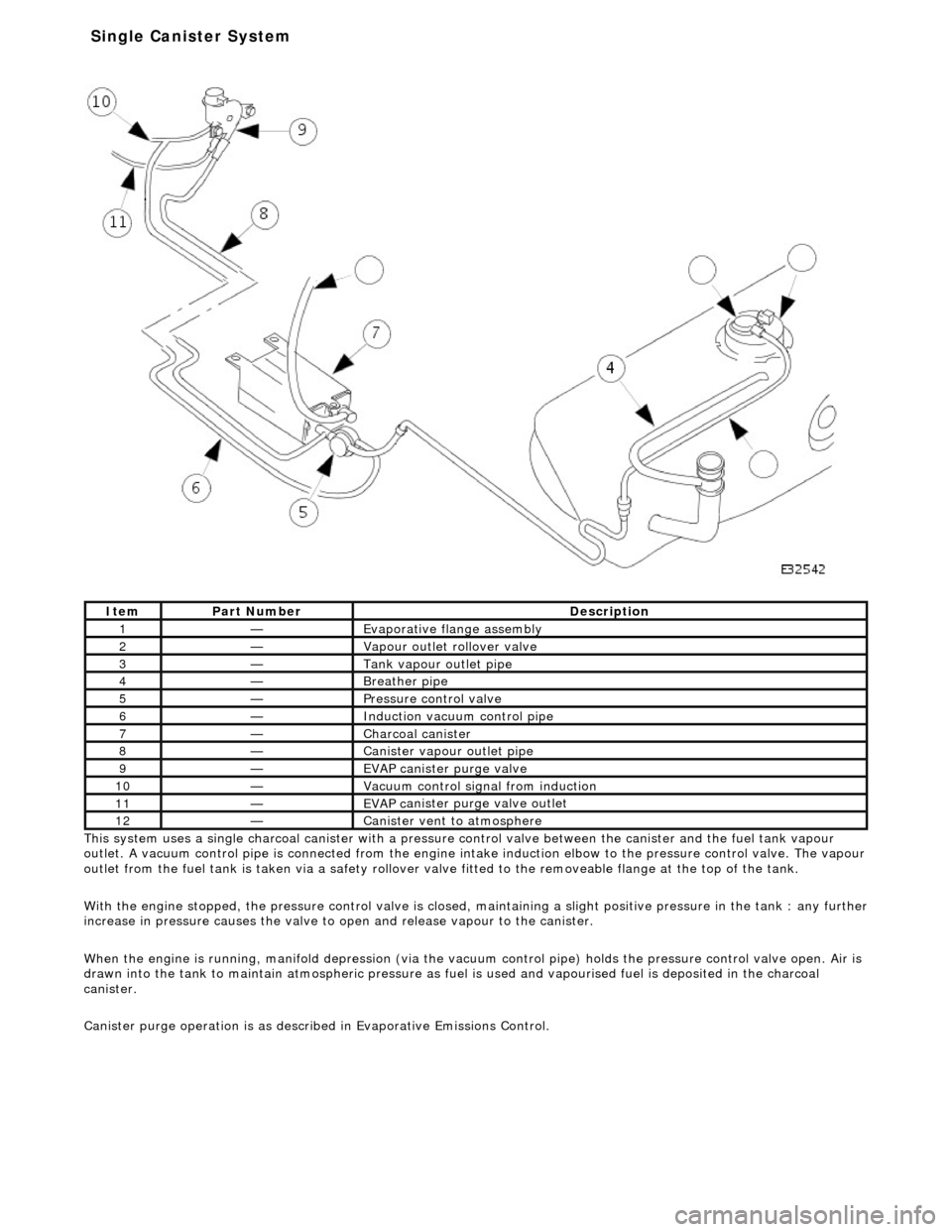
Thi s
system uses a single charcoal canister with a pressure
control valve between the canister and the fuel tank vapour
outlet. A vacuum control pipe is connecte d from the engine intake induction elbow to the pressure control valve. The vapour
outlet from the fuel tank is taken via a safety rollover valve fitted to the re moveable flange at the top of the tank.
With the engine stopped, the pressure control valve is closed, maintaining a slight positive pre ssure in the tank : any further
increase in pressure causes the valve to open and release vapour to the canister.
When the engine is running, manifold depr ession (via the vacuum control pipe) holds the pressure control valve open. Air is
drawn into the tank to maintain atmospheric pressure as fuel is used and vapourised fuel is deposited in the charcoal
canister.
Canister purge operation is as described in Evaporative Emissions Control.
It e
m
Par
t
Number
De
scr
iption
1—Evaporative flan
ge assembly
2—Vapour outlet rol
lover valve
3—Tank vapour outlet pipe
4—Breather
pipe
5—Pressure control valve
6—Induct
ion vacuum control pipe
7—Charcoal can
i
ster
8—Canister vapour outlet pipe
9—EVAP canister purge v
a
lve
10—Vacuu
m
control sign
al from induction
11—EVAP ca
nister purge valve outlet
12—Canist
er vent
to atmosphere
Single Ca
nister System
Page 1151 of 2490
The evaporative l
oss flange assembly is fitted to the top of the tank via a seal and locking ring. The assembly is removeable
complete with the fitted components.
The vapour vent / rollover valve is a push fit via a sealing grommet. The fuel pump connector is push fitted and crimped
into a location tube on the underside of the flange.
It
em
Par
t Number
De
scription
1—Vapour vent /
rollover protection valve
2—Fue
l pump connector
3—Evaporative loss flange locking rin
g
Evaporative Flang
e Assembly
Page 1152 of 2490
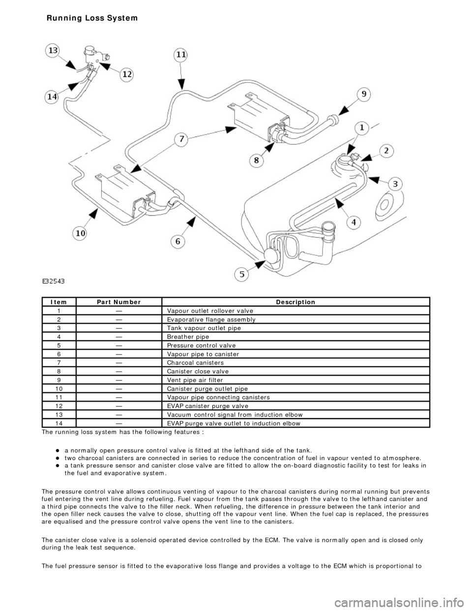
The ru nning loss
system has the following features :
a
normall
y open pressure control valve is fi
tted at the lefthand side of the tank.
two charcoal
canisters are connected in series to reduce th
e concentration of fuel in vapour vented to atmosphere.
a t
ank pressure sensor and canister close
valve are fitted to allow the on-board di agnostic facility to test for leaks in
the fuel and evaporative system.
The pressure control valve allows continuo us venting of vapour to the charcoal canisters during normal running but prevents
fuel entering the vent line duri ng refueling. Fuel vapour from the tank passes through the valve to the lefthand canister and
a third pipe connects the valve to the fill er neck. When refueling, the difference in pressure betw een the tank interior and
the open filler neck causes the valve to cl ose, shutting off the vapour vent line. Wh en the fuel cap is replaced, the pressures
are equalised and the pressure control valve opens the vent line to the canisters.
The canister close valve is a solenoid operated device controlled by the ECM. The valve is normally open and is closed only
during the leak test sequence.
The fuel pressure sensor is fitted to th e evaporative loss flange and provides a volt age to the ECM which is proportional to
Ite
m
Par
t
Number
De
scr
iption
1—Vapour outl
et rol
lover valve
2—Evaporative flan
ge assembly
3—Tank vapour outlet pipe
4—Breather pipe
5—Pressure control
valve
6—Vapour pipe to canister
7—Charcoal cani
sters
8—Cani
st
er close valve
9—Vent pi
pe ai
r filter
10—Canister purge ou
tlet pipe
11—Vapour pipe conn
ecting canisters
12—EVAP canister purge v
a
lve
13—Vacuu
m
control signal from induction elbow
14—EVAP pu
rge valve outlet to induction elbow
Running Loss Sys
tem
Page 1153 of 2490
tank vapou
r pressure.
Canister purge operation is as described in Evaporative Emissions Control.
Evaporative Flange Assembly
The evaporative loss flange assembly is fitted to the top of the tank via a seal and locking ring. The assembly is removeable
complete with the fitted components.
The vapour vent / rollover valve and pressure sensor are a pu sh fit via sealing grommets. The fuel pump connector is push
fitted and crimped into a location tu be on the underside of the flange.
It
em
Par
t Number
De
scription
1—Vapour vent /
rollover protection valve
2—Pres
sure sensor
3—Fue
l pump connector
4—Evaporative loss flange locking rin
g
Page 1154 of 2490
The pressure co ntrol val
ve is fa
stened by adhesive to the lefthand side of the tank. It is a non-serviceable component.
Ite
m
Par
t
Number
De
scr
iption
1—Pressure control
valve
2—Fill
er neck pressure sensing pipe
3—Vapour pipe fro
m ta
nk
4—Vapour outlet pipe to u
n
derfloor canister
P
r
essure Control Valve
Page 1155 of 2490
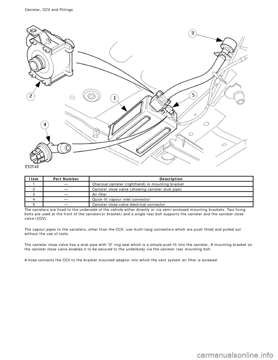
T
he canisters are fixed to the underside of the vehicle either
directly or via semi-enclosed mounting brackets. Two fixing
bolts are used at the front of the canister(or bracket) and a single rear bolt supports the canister and the canister close
valve (CCV).
The vapour pipes to the canisters, other than the CCV, use multi-tang connectors which are push fitted and pulled out
without the use of tools.
The canister close valve has a stub pipe with 'O' ring seal wh ich is a simple push fit into the canister. A mounting bracket on
the canister close valve enables it to be secured to the underbody via the canister rear mounting bolt.
A hose connects the CCV to the bracket mounted adaptor into which the vent system air filter is screwed.
It
em
Par
t Number
De
scription
1—C
harcoal canister (righthand) in mounting bracket
2—Cani
ster close valve (showi
ng canister stub pipe)
3—Ai
r filter
4—Q
uick-fit vapour inlet connector
5—Cani
ster close valve electrical connector
Canister, CCV an
d Fittings
Page 1156 of 2490
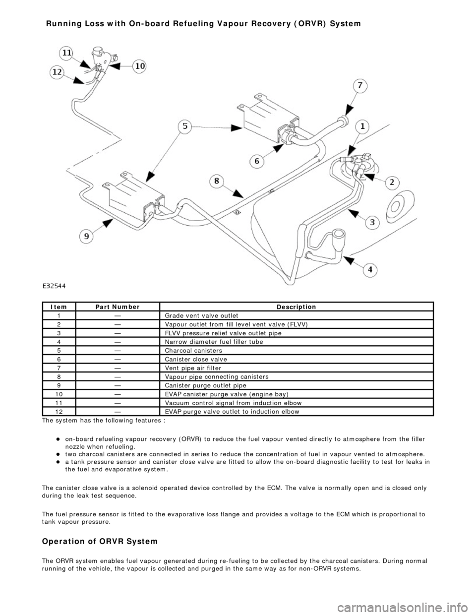
The system has the
following features :
o
n
-board refueling vapour recovery (ORVR) to reduce the fu
el vapour vented directly to atmosphere from the filler
nozzle when refueling.
two ch arcoal
canisters are connected in series to reduce th
e concentration of fuel in vapour vented to atmosphere.
a t
ank pressure sensor and canister close
valve are fitted to allow the on-board di agnostic facility to test for leaks in
the fuel and evaporative system.
The canister close valve is a solenoid operated device controlled by the ECM. The valve is normally open and is closed only
during the leak test sequence.
The fuel pressure sensor is fitted to th e evaporative loss flange and provides a volt age to the ECM which is proportional to
tank vapour pressure.
Op era
tion of ORVR System
The ORVR system enabl
e
s fuel vapour generated during re-fueling to be collected by
the charcoal canisters. During normal
running of the vehicle, the vapour is collected and purged in the same way as for non-ORVR systems.
Ite
m
Par
t
Number
De
scr
iption
1—Grade vent
valve outl
et
2—Vapour outl
et from fil
l level vent valve (FLVV)
3—F
L
VV pressure relief valve outlet pipe
4—N
a
rrow diameter fuel filler tube
5—Charcoal can
i
sters
6—Cani
st
er close valve
7—Vent pi
pe ai
r filter
8—Vapour pipe
conn
ecting canisters
9—Canister purge ou
tlet pipe
10—EVAP canister purge v a
lve (engine bay)
11—Vacuu
m
control signal from induction elbow
12—EVAP pu
rge valve outlet to induction elbow
Running Loss with On-board R
efuelin
g Vapour Recovery (ORVR) System
Page 1158 of 2490
The fuel fil
ler cap is the same as
that used on non-ORVR systems.
The check valve assembly is a push fit into the end of the fuel filler tube and is accessible with the evaporative flange
removed. The valve has a light spring load ing and opens under the inflow of fuel.
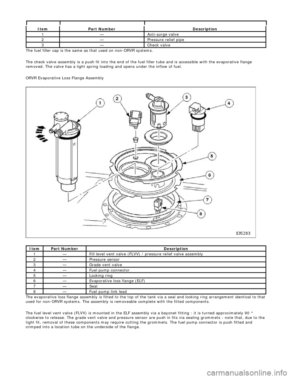
ORVR Evaporative Loss Flange Assembly
The evaporative loss flange assembly is fitted to the top of the tank via a seal and locking ring arrangement identical to that
used for non-ORVR systems. The assembly is re moveable complete with the fitted components.
The fuel level vent valve (FLVV) is mounted in the ELF assembly via a bayonet fitting : it is turned approximately 90 °
clockwise to release. The grade vent valve and pressure sensor are push in fits via sealing gromme ts : note that, due to the
tight fit, removal of these components may require cutting the grommets. The fuel pump connector is push fitted and
crimped into a location tube on the underside of the flange.
It e
m
Par
t
Number
De
scr
iption
1—An
ti-s
urge valve
2—Pressure rel
i
ef pipe
3—Check v
a
lve
It
e
m
Par
t
Number
De
scr
iption
1—Fi
ll
level vent valve (FLVV) /
pressure relief valve assembly
2—Pres
sure
sensor
3—Grade vent
valve
4—Fue
l
pump connector
5—Lockin
g rin
g
6—Evaporative loss flange (ELF)
7—Seal
8—F
u
el pump link lead