1998 JAGUAR X308 Ground
[x] Cancel search: GroundPage 1047 of 2490
14
.
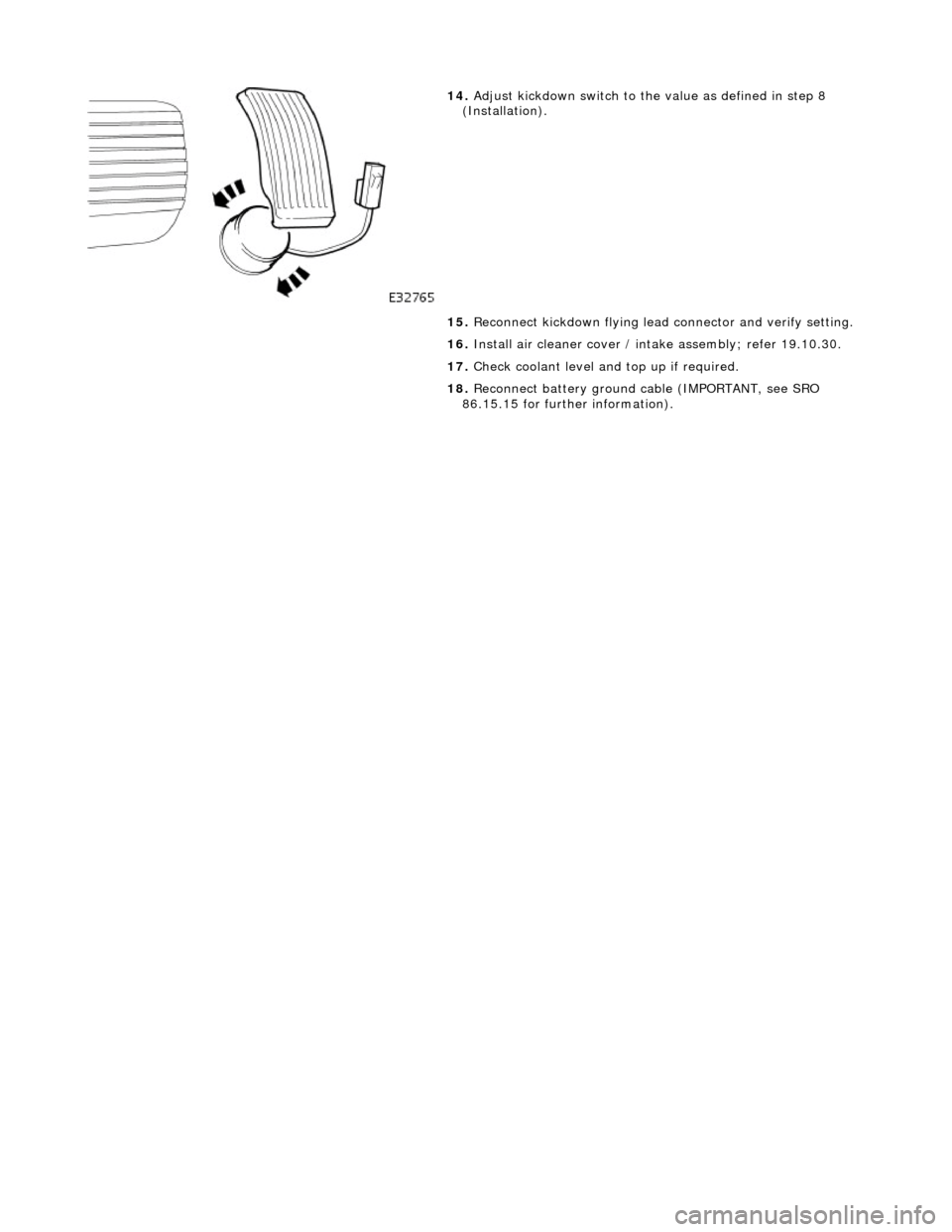
Adjust kickdown switch to th e value as defined in step 8
(Installation).
15. Reconnect kickdown flying lead connector and verify setting.
16. Install air cleaner cover / intake assembly; refer 19.10.30.
17. Check coolant level and top up if required.
18. Reconnect battery ground cable (IMPORTANT, see SRO
86.15.15 for further information).
Page 1065 of 2490
The BPM
'CRANK SELECTED' terminal is ta
ken to 0V by the ignition switch.
The BPM
'O/P ENGINE CRANK' terminal pr
ovides a path to ground for the starte r relay coil, via Fuse 5 (10A) located
in the engine compartment front fusebo x. This path to ground also indicates to the ECM 'I/P ENGINE CRANK'
terminal, by taking it to 0V, that the engine has been requested to crank.
Wi
th the starter relay contacts closed,
power via Fuse 3 (25A) in the engine compartment rear fusebox, is supplied
to the pull-in winding of the starter solenoid.
The s
olenoid main contacts close and are held
closed by the solenoid hold-in winding.
Battery power is supplied
to
the starter motor through the solenoid main contacts, direct from the battery and the
High Power Protection Module.
Starter
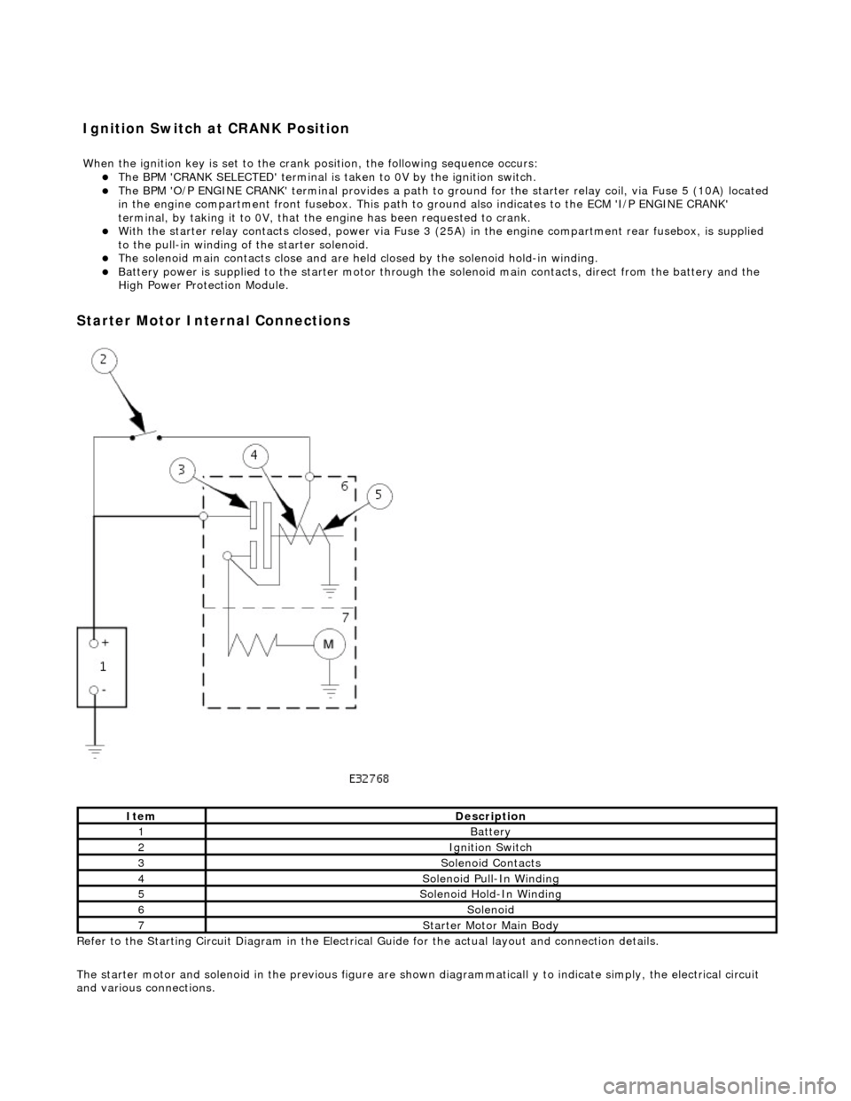
Motor Internal Connections
Re
fer to the Starting Circuit Diagram in the Electrical
Guide for the actual layout and connection details.
The starter motor and solenoid in the previous figure are shown diagrammaticall y to indicate simply, the electrical circuit
and various connections.
It
em
De
scription
1Batt
ery
2Ignition Switch
3So
lenoid Contacts
4So
lenoid Pull-In Winding
5So
lenoid Hold-In Winding
6So
lenoid
7St
arter Motor Main Body
I
gnition Switch at CRANK Position
W
hen the ignition key is set to the crank position, the following sequence occurs:
Page 1067 of 2490
Pinpoint Tests
DT
C
De
scription
Possib
le Source
Acti
on
P1245Engine
crank signal low
voltage
Starter relay
coil to
ECM/BPM circuit open
circuit
F
or starter relay circuit tests,GO to
Pinpoint Test B.
.
P1246Engine
crank signal high
voltage
Starter relay
coil to ECM/BPM circuit short
circuit to B+ voltage
B
PM failure
F
or starter relay circuit tests,GO to
Pinpoint Test B.
.
P
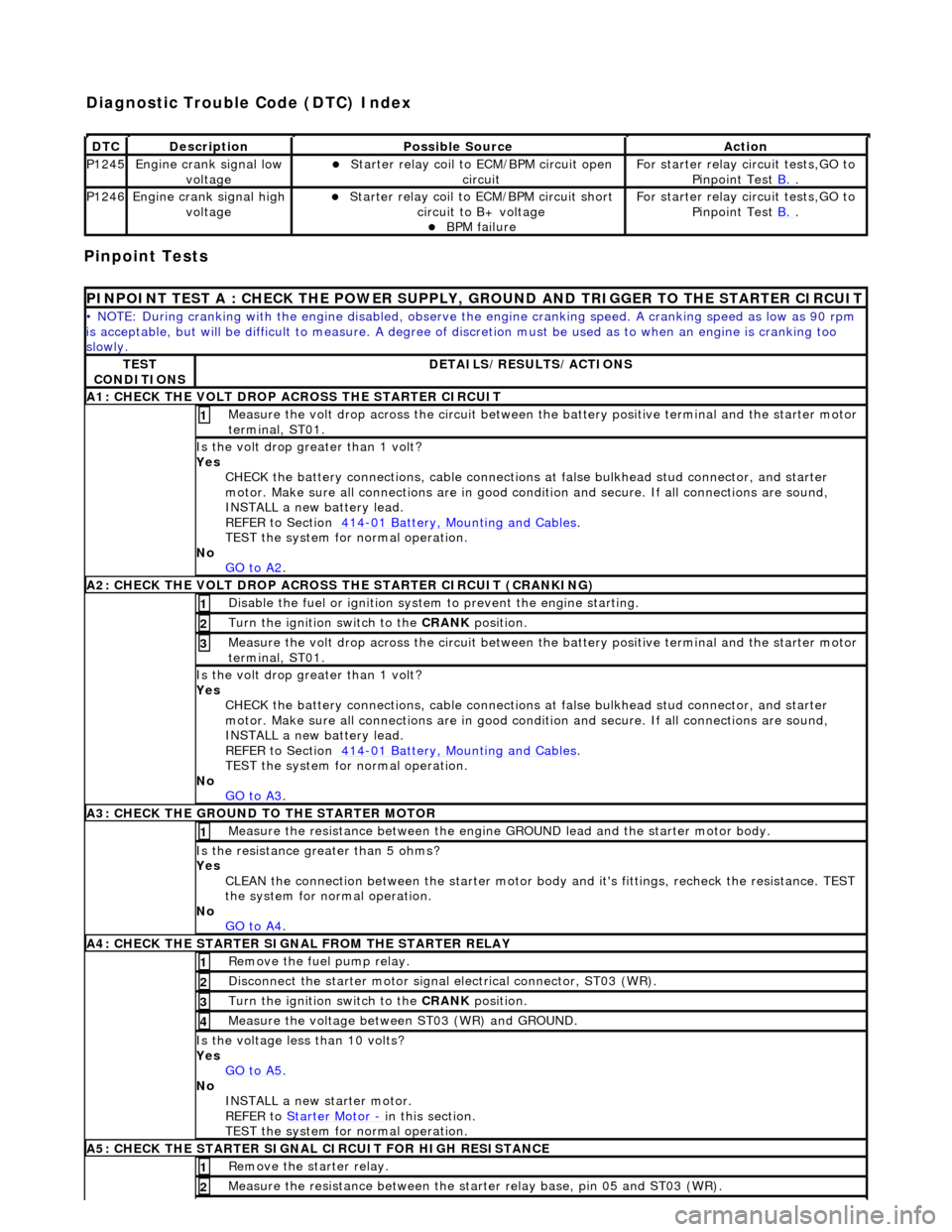
INPOINT TEST A : CHECK THE
POWER SUPPLY, GROUND AND TRI GGER TO THE STARTER CIRCUIT
•
NOTE: During cranking with the engine disabled, observe the engine cranking speed. A cranking speed as low as 90 rpm
is acceptable, but will be difficult to measure. A degree of discretion must be used as to when an engine is cranking too
slowly.
TE
ST
CONDITIONS
D
ETAILS/RESULTS/ACTIONS
A1: CHECK
THE VOLT DROP AC
ROSS THE STARTER CIRCUIT
M
easure the volt drop across the circuit between the battery positive terminal and the starter motor
terminal, ST01.
1
Is the vol
t drop greater than 1 volt?
Yes CHECK the battery connections, cable connections at false bulkhead stud connector, and starter
motor. Make sure all connections are in good co ndition and secure. If all connections are sound,
INSTALL a new battery lead.
REFER to Section 414
-0
1 Battery, Mounting and Cables
.
TEST the system
for normal operation.
No GO to A2
.
A2: CHECK
THE VOLT DROP ACROSS
THE STARTER CIRCUIT (CRANKING)
Di
sable the fuel or ignition system to prevent the engine starting.
1
Turn the ignition swi
tch to the CRANK
position.
2
M
easure the volt drop across the circuit between the battery positive terminal and the starter motor
terminal, ST01.
3
Is the vol
t drop greater than 1 volt?
Yes CHECK the battery connections, cable connections at false bulkhead stud connector, and starter
motor. Make sure all connections are in good co ndition and secure. If all connections are sound,
INSTALL a new battery lead.
REFER to Section 414
-0
1 Battery, Mounting and Cables
.
TEST the system
for normal operation.
No GO to A3
.
A3:
CHECK THE GROUND TO THE STARTER MOTOR
Meas
ure the resistance between the engine GROUND lead and the starter motor body.
1
Is th
e resistance greater than 5 ohms?
Yes CLEAN the connection between the starter motor body and it's fittings, recheck the resistance. TEST
the system for normal operation.
No GO to A4
.
A4
: CHECK THE STARTER SIGNAL FROM THE STARTER RELAY
R
emove the fuel pump relay.
1
Di
sconnect the starter motor signal
electrical connector, ST03 (WR).
2
Turn the ignition swi
tch to the CRANK
position.
3
M
easure the voltage between ST03 (WR) and GROUND.
4
Is th
e voltage less than 10 volts?
Yes GO to A5
.
No
INSTALL a new starter motor.
REFER to Starter Motor
-
in t
his section.
TEST the system for normal operation.
A5
: CHECK THE STARTER SIGNAL CIRCUIT FOR HIGH RESISTANCE
R
emove the starter relay.
1
Meas
ure the resistance between the st
arter relay base, pin 05 and ST03 (WR).
2
Diagnostic Trouble Code (D
TC) Index
Page 1068 of 2490
Is the res
istance greater than 5 ohms?
Yes REPAIR the high resistance circui t. For additional information, refer to the wiring diagrams. CLEAR
the DTC. TEST the system for normal operation.
No GO to B1
.
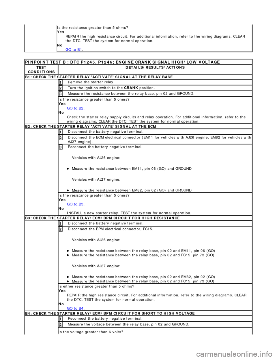
PINPOINT TES
T B : DTC P1245, P1246; ENGINE CRANK SIGNAL HIGH/LOW VOLTAGE
TE
S
T
CONDITIONS
D E
TAILS/RESULTS/ACTIONS
B1: CHECK
THE STARTER
RELAY 'ACTIV
ATE' SIGNAL AT THE RELAY BASE
Re
move the starter relay.
1
Turn the ignition swi
t
ch to the CRANK
position.
2
Measure t
he resistance between th
e relay base, pin 02 and GROUND.
3
Is the res
istance greater than 5 ohms?
Yes GO to B2
.
No Check t
he starter relay supply circui
ts and relay operation. For additi onal information, refer to the
wiring diagrams. CLEAR the DTC. TEST the system for normal operation.
B2: CHECK THE STARTER
RELAY 'A
CTIVATE' SIGNAL AT THE ECM
Disc
onnect the battery negative terminal.
1
D
i
sconnect the ECM electrical connector (EM11 for vehicles with AJ26 engine
, EM82 for vehicles with
AJ27 engine).
2
R e
connect the battery negative terminal.
Vehicles with AJ26 engine:
Meas ure t
he resistance between EM11, pin 06 (GO) and GROUND
Vehicles with AJ27 engine:
Meas ure t
he resistance between EM82, pin 02 (GO) and GROUND
3
Is th
e res
istance greater than 5 ohms?
Yes GO to B3
.
No
IN
STALL a new starter relay. TEST
the system for normal operation.
B3: CHECK THE STARTER
RELAY/ECM/BPM CIRCUIT FOR HIGH RESISTANCE
Di sc
onnect the battery negative terminal.
1
Disc
onne
ct the BPM electrical connector, FC15.
Vehicles with AJ26 engine:
Meas ure t
he resistance between the relay
base, pin 02 and EM11, pin 06 (GO)
Measure t
he resistance between the relay
base, pin 02 and FC15, pin 73 (GO)
Vehicles with AJ27 engine:
Meas ure t
he resistance between the relay
base, pin 02 and EM82, pin 02 (GO)
Measure t
he resistance between the relay
base, pin 02 and FC15, pin 73 (GO)
2
Is either resistance greater
than 5 ohms?
Yes REPAIR the high resistance circui t. For additional information, refer to the wiring diagrams. CLEAR
the DTC. TEST the system for normal operation.
No GO to B4
.
B4: CHECK THE STARTER
RE
LAY/ECM/BPM CIRCUIT FOR SHORT TO HIGH VOLTAGE
Re
connect the battery negative terminal.
1
Meas
ure t
he voltage between the
relay base, pin 02 and GROUND.
2
Is the volt
age greater than 6 volts?
Page 1069 of 2490
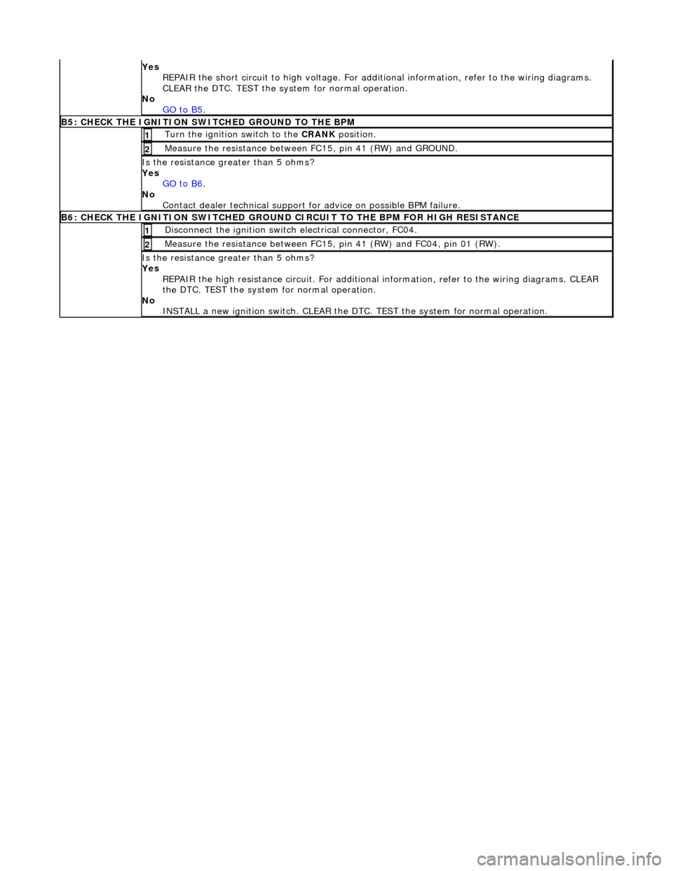
Yes
REPAIR the short circuit to high voltage. For addi tional information, refer to the wiring diagrams.
CLEAR the DTC. TEST the syst em for normal operation.
No GO to B5
.
B5: CHECK
THE IGNITION SWITCHED GROUND TO THE BPM
Turn the ignition swi
tch to the CRANK
position.
1
Meas
ure the resistance between FC15, pin 41 (RW) and GROUND.
2
Is th
e resistance greater than 5 ohms?
Yes GO to B6
.
No
Contact dealer technical support fo r advice on possible BPM failure.
B6: CHECK
THE IGNITION SWIT
CHED GROUND CIRCUIT TO THE BPM FOR HIGH RESISTANCE
Di
sconnect the ignition switch electrical connector, FC04.
1
Meas
ure the resistance between FC15,
pin 41 (RW) and FC04, pin 01 (RW).
2
Is th
e resistance greater than 5 ohms?
Yes REPAIR the high resistance circui t. For additional information, refer to the wiring diagrams. CLEAR
the DTC. TEST the system for normal operation.
No INSTALL a new ignition switch. CLEAR the DTC. TEST the system for normal operation.
Page 1070 of 2490
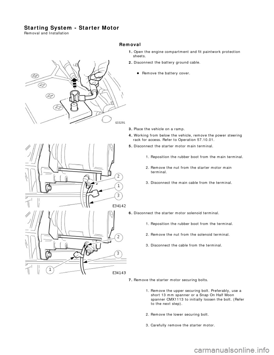
Starting System - Starter Motor
Remo
val and Installation
Remov
a
l
1.
Op
en the engine compartment and fit paintwork protection
sheets.
2. Disc
onnect the batt
ery ground cable.
Re
move the battery cover.
3. Place the vehicle on a ramp.
4. Working from below the vehicle, remove the power steering
rack for access. Refer to Operation 57.10.01.
5. Disc
onnect the starter motor main terminal.
1. Reposition the rubber b oot from the main terminal.
2. Remove the nut from the starter motor main terminal.
3. Disconnect the main cable from the terminal.
6. Di
sconnect the starter motor solenoid terminal.
1. Reposition the rubber boot from the terminal.
2. Remove the nut from the solenoid terminal.
3. Disconnect the cable from the terminal.
7. Remove the starter mo tor securing bolts.
1. Remove the upper securing bolt. Preferably, use a short 13 mm spanner or a Snap On Half Moon
spanner CMX1113 to initially loosen the bolt. (Refer
to the next step).
2. Remove the lower securing bolt.
3. Carefully remove the starter motor.
Page 1073 of 2490
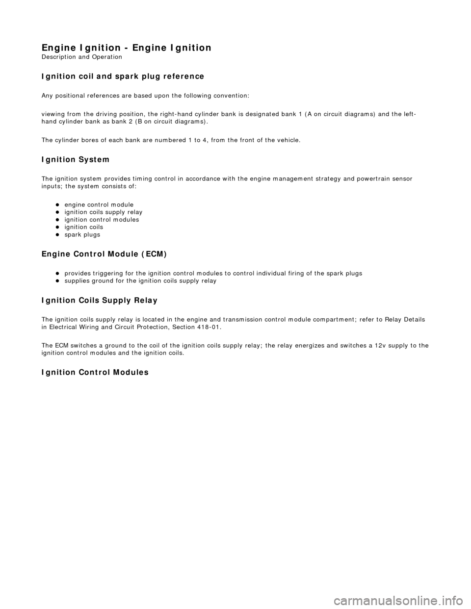
Engine Igni
tion -
Engine Ignition
Description an
d Operation
I
gnition coil and spark plug reference
Any positional r
eferences are base
d upon the following convention:
viewing from the driving position, the right-hand cylinder bank is designated bank 1 (A on circuit diagrams) and the left-
hand cylinder bank as bank 2 (B on circuit diagrams).
The cylinder bores of each bank are number ed 1 to 4, from the front of the vehicle.
Ig
nition System
Th
e ignition system provides timing cont
rol in accordance with the engine mana gement strategy and powertrain sensor
inputs; the system consists of:
engine
control module
igni
tion coils supply relay
ignit
ion control modules
igni
tion coils
spark plu
gs
Engine Control Module (ECM)
pr
ovides triggering for the ignition control modules
to control individual firing of the spark plugs
supplies ground for
the igni
tion coils supply relay
I
gnition Coils Supply Relay
The
ignition coils supply relay is located
in the engine and transmission control mo dule compartment; refer to Relay Details
in Electrical Wiring and Circuit Protection, Section 418-01.
The ECM switches a ground to the coil of the ignition coils supply relay; the relay energizes and switches a 12v supply to the
ignition control modules and the ignition coils.
I
gnition Control Modules
Page 1078 of 2490
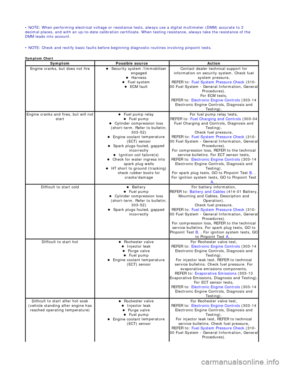
• NO
TE: When performing electrical voltag
e or resistance tests, always use a digital multimeter (DMM) accurate to 3
decimal places, and with an up-t o-date calibration certificate. When testing resistance, always take the resistance of the
DMM leads into account.
• NOTE: Check and rectify basic faults before beginning diagnostic ro utines involving pinpoint tests.
Sym
ptom Chart
Sy
m
ptom
Possib
l
e source
Acti
o
n
Engine
cranks, but does
not fire
Secu
rit
y system /Immobiliser
engaged
Harness Fue l
system
ECM fault
Contact deal er techni
cal support for
information on security system. Check fuel
system pressure,
REFER to: Fuel System Pressure Check
(310
-
00 Fuel System - Genera l Information, General
Procedures).
For ECM tests,
REFER to: Electronic Engine Controls
(303
-14
Electronic Engine Co ntrols, Diagnosis and
Testing).
Engine cranks and
fi
res, but will not
start
Fu
el pump relay
Fuel
pump
Cyl
i
nder compression loss
(short-term. Refer to bulletin; 303-52)
Engine coolan t
temperature
(ECT) sensor
Spark plugs fouled, gapp
ed
incorrectly
Ignition coil fail
ure(s)
Check f
o
r water ingress into
spark plug wells
HT sho rt to ground (tracking)
check rubber
boots for
cracks/damage
Fo
r fuel pump relay tests,
REFER to: Fuel Charging and Controls
(303
-04
Fuel Charging and Controls, Diagnosis and Testing).
Check fuel pressure,
REFER to: Fuel System Pressure Check
(310
-
00 Fuel System - Genera l Information, General
Procedures).
For compression loss, REFER to the technical service bulletins. For ECT sensor tests,
REFER to: Electronic Engine Controls
(303
-14
Electronic Engine Co ntrols, Diagnosis and
Testing).
For spark plug tests, GO to Pinpoint Test B.
.
For ign i
tion system tests, GO to Pinpoint Test
A.
.
Diff
icult to start cold
Batt
ery Fuel
pump
Cyl
i
nder compression loss
(short-term. Refer to bulletin; 303-52)
Spark plugs fouled, gapp
ed
incorrectly
F o
r battery information,
REFER to: Battery and Cables
(414
-01 Battery,
Mounting and Cables, Description and Operation).
Check fuel pressure.
REFER to: Fuel System Pressure Check
(310
-
00 Fuel System - Genera l Information, General
Procedures).
For compression loss, REFER to the technical service bulletins. For spark plug tests, GO to
Pinpoint Test B.
. For ig
nition system tests, GO
to Pinpoint Test A.
.
Diff
icult to start hot
Roc
h
ester valve
Injec
t
or leak
Purge
val
ve
Fue
l
pump
Engine coolan
t
temperature
(ECT) sensor
F or R
ochester
valve test,
REFER to: Electronic Engine Controls
(303
-14
Electronic Engine Co ntrols, Diagnosis and
Testing).
For injector leak test, REFER to technical
service bulletins. Check fuel pressure. For evaporative emissions components,
REFER to: Evaporative Emissions
(303
-13
Evaporative Emissions, Diagnosis and Testing).
For ECT sensor tests,
REFER to: Electronic Engine Controls
(303
-14
Electronic Engine Co ntrols, Diagnosis and
Testing).
D iff
icult to start after hot soak
(vehicle standing after engine has reached operating temperature)
Roc h
ester valve
Injec
t
or leak
Purge
val
ve
Fue
l
pump
Engine coolan
t
temperature
(ECT) sensor
F or R
ochester
valve test,
REFER to: Electronic Engine Controls
(303
-14
Electronic Engine Co ntrols, Diagnosis and
Testing).
For injector leak test, REFER to technical service bulletins. Check fuel pressure,
REFER to: Fuel System Pressure Check
(310
-
00 Fuel System - Genera l Information, General
Procedures).