Page 1123 of 2490
2.
Conne
ct hoses to charge air cooler.
Conne
ct hoses.
3. Install intake air te mperature sensor 2 to charge air cooler;
refer to 18.30.52.
4. Install supercharger; refer to 18.50.15.
5. Install supercharger driv e belt; refer to 18.50.08.
6. Install engine coolant outlet pipe; refer to 26.31.08.
7. Install supercharger outlet du ct and new gasket; refer to
18.50.16.
8. Install throttle intake elbow; refer to 19.70.28.
9. Install exhaust gas re-circulation valve (EGR) if applicable;
refer to 17.45.01.
10. Install throttle body; refer to 19.70.04.
11. Install air cleaner cover / intake assembly; re fer to 19.10.30.
12. Refill cooling system; refer to (SC) (26.10.01).
13. Reconnect battery ground cable (IMPORTANT, see SRO
86.15.15 for further information).
Page 1126 of 2490
Intake Air Distribution and Filtering - Charge Air Cooler Radiator
Remo
val and Installation
Remov
a
l
1.
Op
en the engine compartment and fit paintwork protection
sheets.
2. Disconnect the battery.
1. Remove the battery cover.
2. Disconnect the battery ground cable.
3. Remove the engine radiator and air conditioning condensor
assembly. Refer to operation 26.40.01.
4. Remove the grill assembly fo r access. Refer to operation
76.55.15.
5. Drain th e charge air cooler radiator.
Reach t
hrough the front bumper
splitter vane to remove
the radiator drain plug.
6. Disc
onnect the radiator
hoses from the radiator.
1. Disconnect the coolant pump to radiator hose.
2. Disconnect the return hose.
3. Disconnect the bleed pipe.
7. Re
move the two radiator fixing bolts.
8. Displace and re-position the am bient air temperature sensor
and bracket.
Page 1128 of 2490

Intake Air Distribution and Filtering - Supercharger
Remo
val and Installation
Remov
a
l
Installation
1. Disc onne
ct battery ground cable (IMPORTANT, see SRO
86.15.19 for further information).
2. Drain radiator coolant; refer to 26.10.01.
3. Remove air cleaner cover / intake assembly; refer to 19.10.30.
4. Remove throttle body; refer to 19.70.04.
5. Remove exhaust gas re-circulation valve (EGR) if installed;
refer to 17.45.01.
6. Remove throttle intake elbo w; refer to (SC) 19.70.28.
7. Remove supercharger outlet duct; refer to 18.50.16.
8. Remove coolant outlet pipe; refe r to operation (SC) 26.31.08.
9. Remove supercharger drive belt; refer to 18.50.08.
10. Disconnect remaining coolant hoses from charge air coolers.
Position pipes to facilitate removal
of supercharger.
Inst
al
l suitable blanking plugs.
11 .
R
emove supercharger from engine.
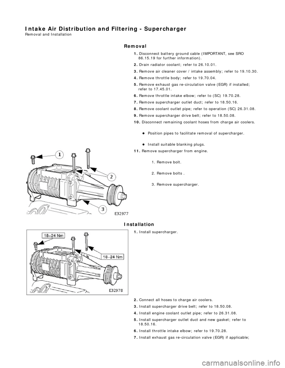
1. Remove bolt.
2. Remove bolts .
3. Remove supercharger.
1. Inst al
l supercharger.
2. Connect all hoses to charge air coolers.
3. Install supercharger driv e belt; refer to 18.50.08.
4. Install engine coolant outlet pipe; refer to 26.31.08.
5. Install supercharger outlet du ct and new gasket; refer to
18.50.16.
6. Install throttle intake elbow; refer to 19.70.28.
7. Install exhaust gas re-circulation valve (EGR) if applicable;
Page 1134 of 2490

Intake Air Distribution and Filtering - Thrott
le Body Elbow
Re
mo
val and Installation
Remov
a
l
1.
WARNING: B E
FORE PROCEEDING, IT IS ESSENTIAL THAT
WARNING NOTES GIVEN IN SECTION 100-00 (UNDER HEADING
'SAFETY PRECAUTIONS') AR E READ AND UNDERSTOOD.
Disconnect battery ground cable (IMPORTANT, see SRO
86.15.19 for further information).
2. Re
move air cleaner cover / inta
ke assembly; refer 19.10.30.
3. Remove throttle assemb ly; refer to 19.70.04.
4. Remove exhaust gas recirculation (EGR) valve where installed;
refer 17.45.01.
5. Re
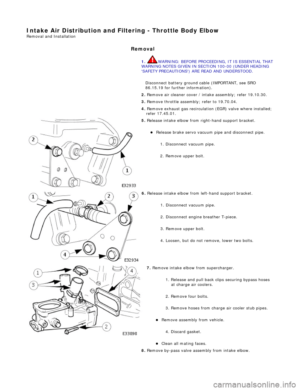
lease intake elbow from right-hand support bracket.
Re
lea
se brake servo vacuum pi
pe and disconnect pipe.
1. Disconnect vacuum pipe.
2. Remove upper bolt.
6. Relea
se intake elbow from le
ft-hand support bracket.
1. Disconnect vacuum pipe.
2. Disconnect engine breather T-piece.
3. Remove upper bolt.
4. Loosen, but do not remove, lower two bolts.
7. Re
move intake elbow from supercharger.
1. Release and pull back cl ips securing bypass hoses
at charge air coolers.
2. Remove four bolts.
3. Remove hoses from charge air cooler stub pipes.
Re move as
sembly from vehicle.
4. Discard gasket.
Cle a
n all mating faces.
8. Remove by-pass valve assembly from intake elbow.
Page 1136 of 2490
2.
Fully tighten two bolts.
3. Connect breather/purge pipe T-piece to intake elbow.
4. Connect vacuum pipe to intake elbow.
5. Install right-hand support brac
ket to intake elbow.
1. Install bolt.
6. Install exhaust gas re-circulation valve (EGR) if applicable;
refer to 17.45.01.
7. Install throttle assemb ly; refer to 19.70.04.
8. Install air cleaner cover / intake assembly; refer to 19.10.30.
9. Reconnect battery ground cable (IMPORTANT, see SRO
86.15.15 for further information).
Page 1137 of 2490
Intake Air Distribution and Filtering - Throt
tle Body Elbow4.0L NA V8 -
AJ27/3.2L NA V8 - AJ26
Re
moval and Installation
Remov
al
S
pecial Tool(s)
Re
lease tool - quick fit
310-044 (JD 182)
R
elease tool 5 /16 - quick fit
310-054 (JD 203)
1. WARNING: BEFORE PROCEEDING, IT IS ESSENTIAL THAT
THE WARNING NOTES GIVEN IN SECTION 100-00 (UNDER THE
HEADING 'SAFETY PRECAUTIONS') ARE READ AND
UNDERSTOOD.
Disconnect battery ground cable (IMPORTANT, see SRO
86.15.19 for further information).
2. D
epressurize fuel sy
stem; refer to 19.50.02
3. Remove air cleaner cover / intake assembly; refer to 19.10.30.
4. Remove throttle body; refer to 19.70.04.
5. R
elease intake elbow from right-hand support bracket.
Re
lease brake servo vacuum pi
pe and disconnect pipe.
1. Disconnect vacuum pipe.
2. Remove bolt.
6. Release intake elbow from le ft-hand support bracket.
1. Disconnect vacuum pipe.
2. Disconnect engine breather T-piece.
3. Remove bolt.
4. Loosen, but do not remove two bolts.
Page 1141 of 2490
2.
Tighten two bolts.
3. Connect breather/p urge pipe T-piece.
4. Connect vacuum pipe.
9. Install righ
t-hand support
bracket to intake elbow.
1. Install bolt.
2. Connect vacuum pipe.
10. Install throttle assemb ly; refer to 19.70.04.
11. Install air cleaner cover / intake assembly; re fer to 19.10.30.
12. Install engine covers.
13. Reconnect battery ground cable (IMPORTANT, see SRO
86.15.15 for further information).
Page 1142 of 2490

Intake Air Distribution and Filtering - Throttle B
ody Elbow4.0L SC V8 -
AJ26
Re mo
val and Installation
Remova
l
1.
WARNING: BE
FORE PROCEEDING, IT IS ESSENTIAL THAT
WARNING NOTES GIVEN IN SECTION 100-00 (UNDER HEADING
'SAFETY PRECAUTIONS') AR E READ AND UNDERSTOOD.
Disconnect battery ground cable (IMPORTANT, see SRO
86.15.19 for further information).
2. Re
move air cleaner cover / inta
ke assembly; refer 19.10.30.
3. Remove throttle assemb ly; refer to 19.70.04.
4. Remove exhaust gas recirculation (EGR) valve where installed;
refer 17.45.01.
5. Re
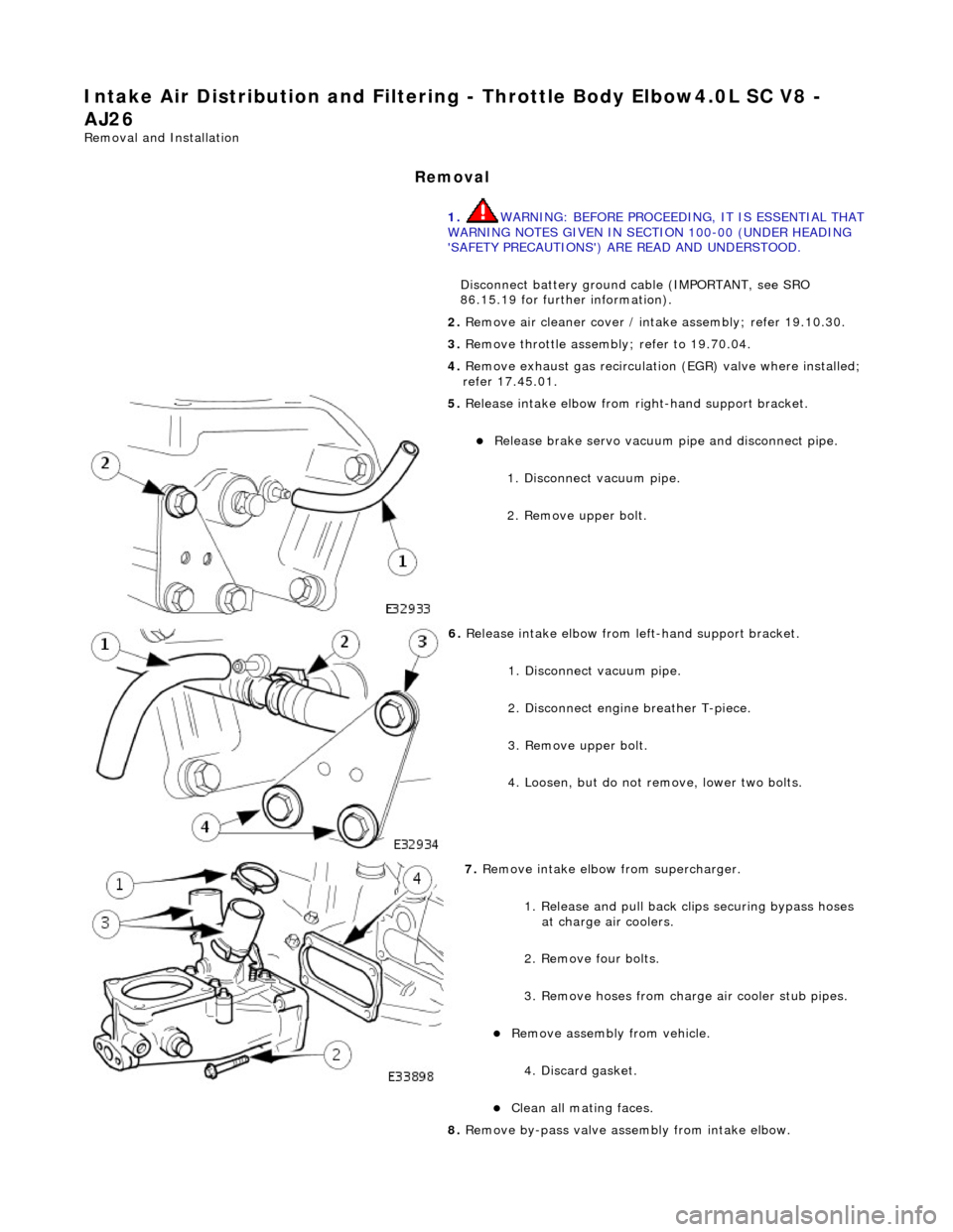
lease intake elbow from right-hand support bracket.
Re
lea
se brake servo vacuum pi
pe and disconnect pipe.
1. Disconnect vacuum pipe.
2. Remove upper bolt.
6. Relea
se intake elbow from le
ft-hand support bracket.
1. Disconnect vacuum pipe.
2. Disconnect engine breather T-piece.
3. Remove upper bolt.
4. Loosen, but do not remove, lower two bolts.
7. Re
move intake elbow from supercharger.
1. Release and pull back cl ips securing bypass hoses
at charge air coolers.
2. Remove four bolts.
3. Remove hoses from charge air cooler stub pipes.
Re move as
sembly from vehicle.
4. Discard gasket.
Cle a
n all mating faces.
8. Remove by-pass valve assembly from intake elbow.