Page 2034 of 2490

Body Closures - Body Closures
Description and Operation
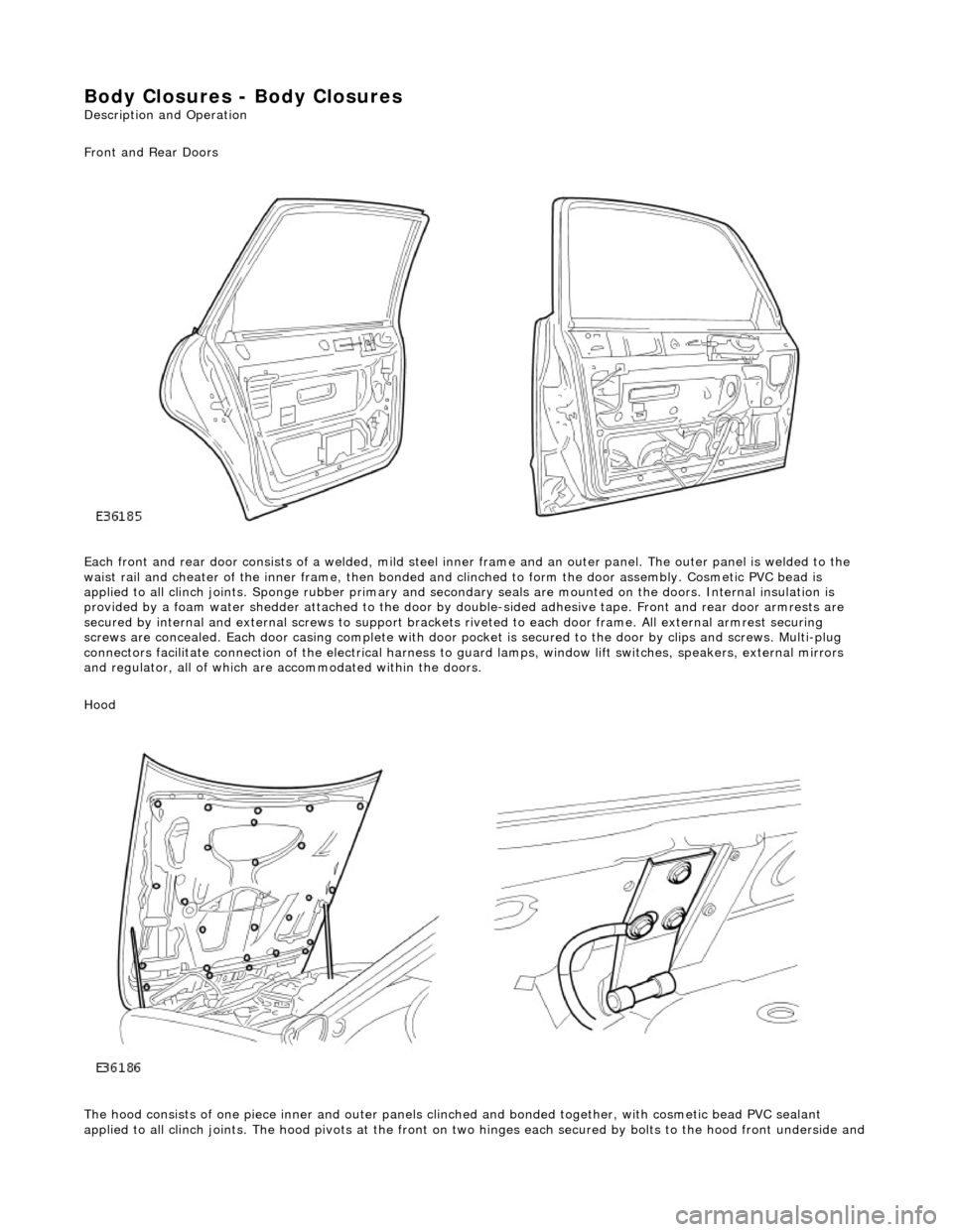
Front and Rear Doors
Each front and rear door consists of a welded, mild steel inner frame and an outer panel. The outer panel is welded to the
waist rail and cheater of the inner frame, then bonded and clinched to fo rm the door assembly. Cosmetic PVC bead is
applied to all clinch joints. Sponge rubber primary and secondary seals are mo unted on the doors. Internal insulation is
provided by a foam water shedder attached to the door by double-sided adhesive tape. Front and rear door armrests are
secured by internal and external screws to support brackets riveted to each door frame . All external armrest securing
screws are concealed. Each door casing complete with door po cket is secured to the door by clips and screws. Multi-plug
connectors facilitate connection of the electrical harness to guard lamps, window lift switches, speakers, external mirrors
and regulator, all of which are accommodated within the doors.
Hood
The hood consists of one piece inner an d outer panels clinched and bonded toge ther, with cosmetic bead PVC sealant
applied to all clinch joints. The hood pivo ts at the front on two hinges each secured by bolts to the hood front underside and
Page 2063 of 2490

Interior Trim and Ornamentation - Floor Covering
Removal and Installation
Removal
1. Remove battery cover and disc onnect ground cable from
battery terminal. Refer to 86.15.19.
2. Remove rear seat cushion. Refer to 76.70.37.
3. Remove front seats. Refer to 76.70.01
4. Remove 'J' gate surroun d. Refer to 76.25.24.
5. Remove centre console finish er veneer panel. Refer to
76.47.26.
6. Remove fascia centre veneer panel. Refer to 76.47.06.
7. Remove centre console assembly. Refer to 76.25.01.
8. Remove 'A' post lower trim pads. Refer to 76.13.30.
9. Remove 'B' post trim pads. Refer to operations in this section.
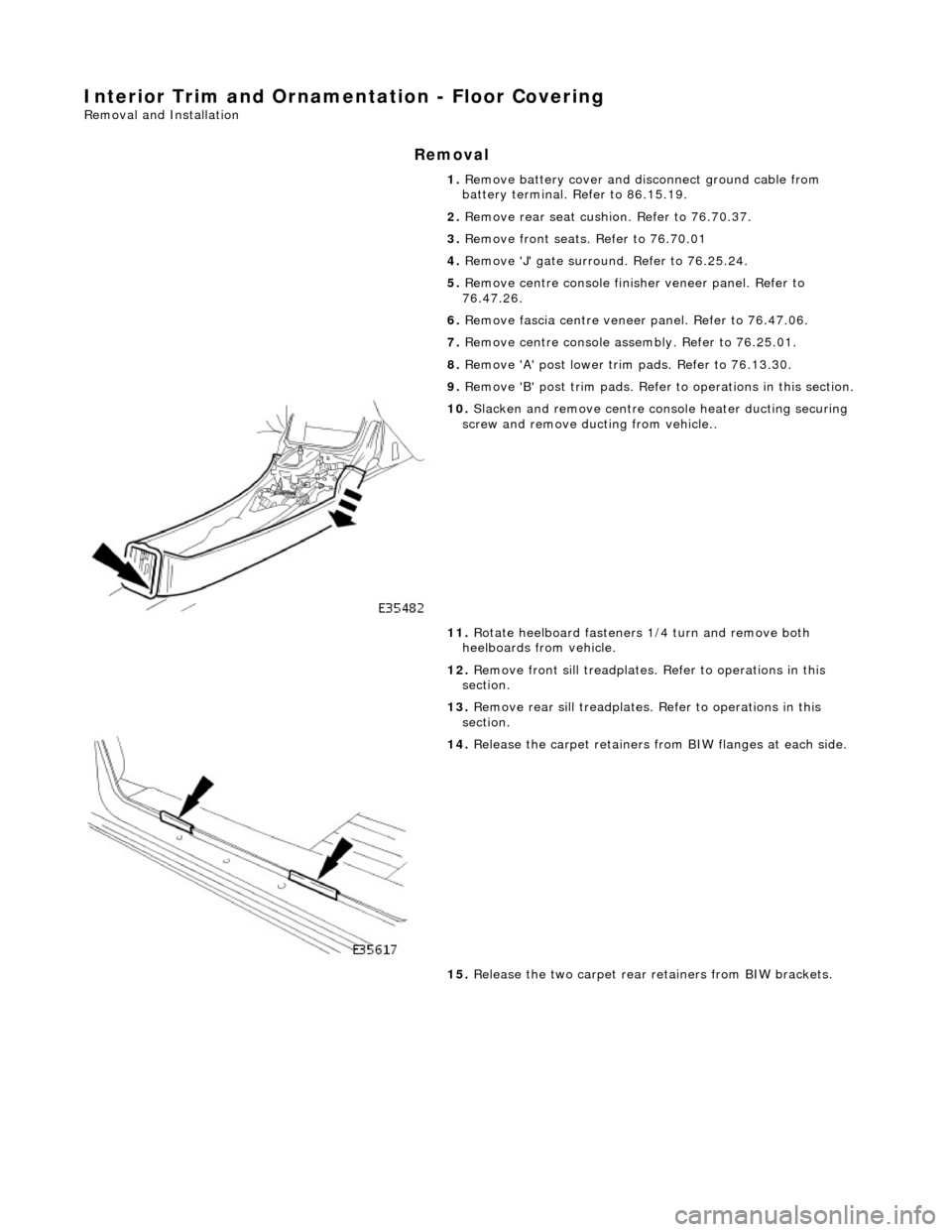
10. Slacken and remove centre console heater ducting securing
screw and remove ducting from vehicle..
11. Rotate heelboard fasteners 1/4 turn and remove both
heelboards from vehicle.
12. Remove front sill treadplates. Refer to operations in this
section.
13. Remove rear sill treadplates. Refer to operations in this
section.
14. Release the carpet retainers fro m BIW flanges at each side.
15. Release the two carpet rear retainers from BIW brackets.
Page 2065 of 2490

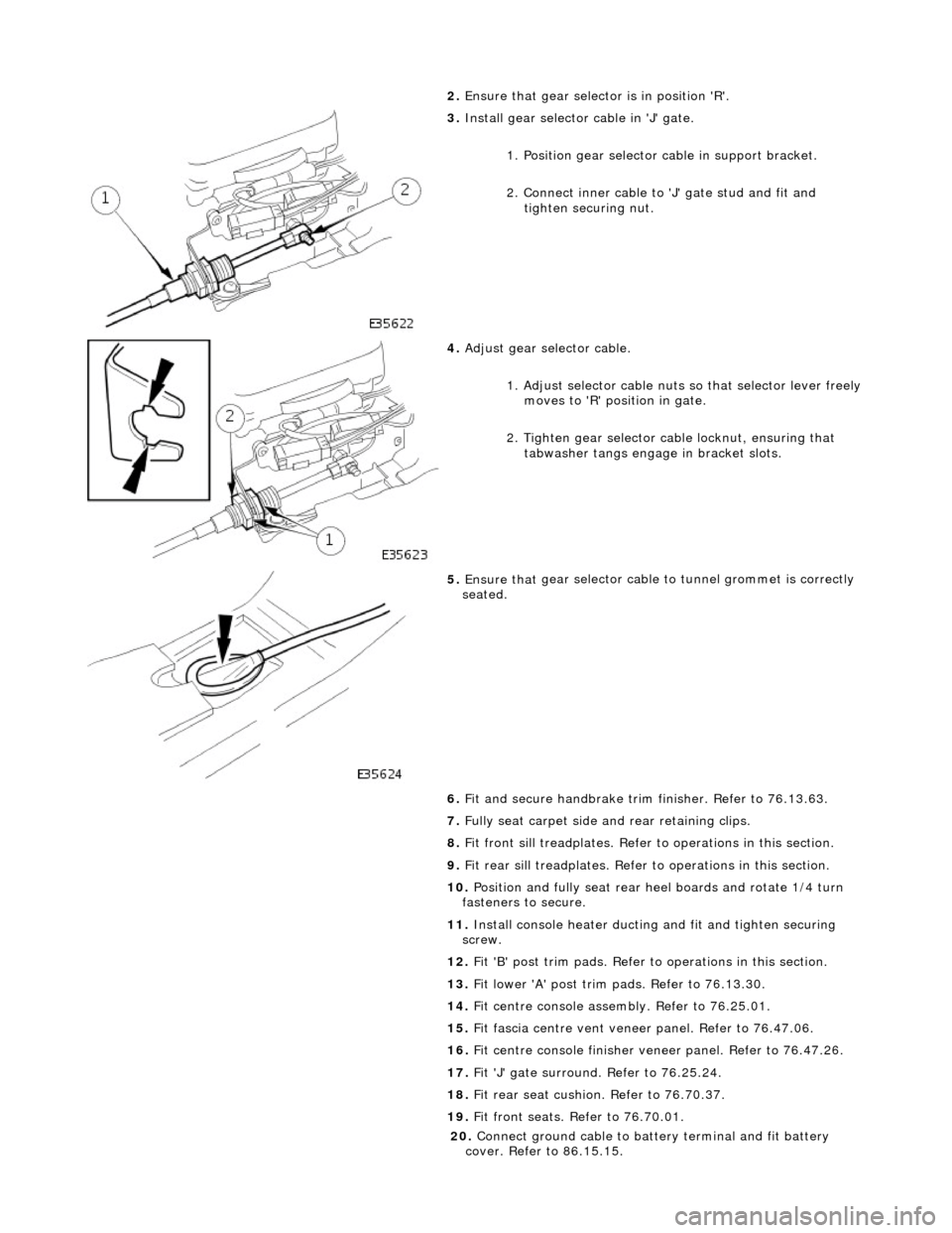
2. Ensure that
gear selector is in position 'R'.
3. Inst
all gear selector cable in 'J' gate.
1. Position gear selector cable in support bracket.
2. Connect inner cable to 'J' gate stud and fit and
tighten securing nut.
4. Adjust
gear selector cable.
1. Adjust selector cable nuts so that selector lever freely
moves to 'R' position in gate.
2. Tighten gear selector ca ble locknut, ensuring that
tabwasher tangs engage in bracket slots.
5. Ensure that
gear selector cable
to tunnel grommet is correctly
seated.
6. Fit and secure handbrake trim finisher. Refer to 76.13.63.
7. Fully seat carpet side and rear retaining clips.
8. Fit front sill treadplates. Refer to operations in this section.
9. Fit rear sill treadplates. Refer to operations in this section.
10. Position and fully seat rear heel boards and rotate 1/4 turn
fasteners to secure.
11. Install console heater ducting and fit and tighten securing
screw.
12. Fit 'B' post trim pads. Refer to operations in this section.
13. Fit lower 'A' post trim pads. Refer to 76.13.30.
14. Fit centre console asse mbly. Refer to 76.25.01.
15. Fit fascia centre ve nt veneer panel. Refer to 76.47.06.
16. Fit centre console finisher vene er panel. Refer to 76.47.26.
17. Fit 'J' gate surround. Refer to 76.25.24.
18. Fit rear seat cushion. Refer to 76.70.37.
19. Fit front seats. Refer to 76.70.01.
20
.
Connect ground cable to batt ery terminal and fit battery
cover. Refer to 86.15.15.
Page 2111 of 2490
Rear View Mirrors - Rear View Mirrors
Description and Operation
Interior Rear View Mirror
The interior rear view mirror is an elec trochromic unit that automatically darken s to prevent glare from following vehicle
lights. This automatic function is selected by pressing the switch at the bottom of the mirror. Pressing the switch again
cancels this function. An LE D then illuminates when automatic dipping is operative.
A Night Sentinel light sensing unit also incorporated in the mi rror casing, provides for automatic control of the vehicle lights.
Door Rear View Mirrors
The door mirrors are cheater mounted, colo r-keyed units, remote electrically adjustable and heated. Adjustment of both
mirrors is carried out from the driver's door switchpack. A slider switch selects the mirror to be adjusted, and a disc switch
adjusts the selected mirror to the required position.
Page 2114 of 2490
Rear View Mirrors - Exterior Mirror
Removal and Installation
Removal
Installation
1.
Fully open door glass and ease top of door casing away from
door Refer to 76.34.01.
2. Remove door frame cheater trim and memory foam for access.
3. Remove mirror assembly from door.
1. Disconnect mirror harness multiplug.
2. Supporting mirror, slacken and remove securing screw and remove mirror assembly from door.
1. Fit exterior mirror assembly to door.
1. Pass harness and multiplu g through cheater aperture
and position mirror foot on cheater, locating the two
dowels correctly and ensuring correct seating on seal.
Fit and tighten the mirror assembly securing screw.
Connect mirror assembly harness multiplug, position in
door and reposition door foam.
2. Fit memory foam and door frame cheater trim.
3. Close door glass.
4. Fit top of door casing. Refer to 76.34.01.
Page 2125 of 2490

Installation
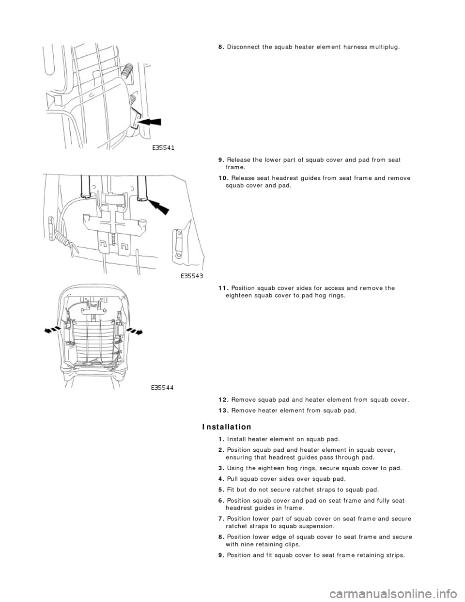
8. Disconnect the squab heater element harness multiplug.
9. Release the lower part of squab cover and pad from seat
frame.
10. Release seat headrest guides from seat frame and remove
squab cover and pad.
11. Position squab cover sides for access and remove the
eighteen squab cover to pad hog rings.
12. Remove squab pad and heater element from squab cover.
13. Remove heater element from squab pad.
1. Install heater element on squab pad.
2. Position squab pad and heater element in squab cover,
ensuring that headrest gu ides pass through pad.
3. Using the eighteen hog rings, secure squab cover to pad.
4. Pull squab cover sides over squab pad.
5. Fit but do not secure ratc het straps to squab pad.
6. Position squab cover and pad on seat frame and fully seat
headrest guides in frame.
7. Position lower part of squab co ver on seat frame and secure
ratchet straps to squab suspension.
8. Position lower edge of squab co ver to seat frame and secure
with nine retaining clips.
9. Position and fit squab cover to seat frame retaining strips.
Page 2128 of 2490
Installation
9. Disconnect the squab heater element harness multiplug (grey).
10. Release the lower part of squab cover and pad from seat
frame.
11. Release seat headrest guides from seat frame and remove
squab cover and pad.
12. Position squab cover sides for access and remove the
eighteen squab cover to pad hog rings.
13. Remove staples securing squab cover to squab pad and
heater element.
14. Remove headrest guid es from squab cover.
1. Fit and fully seat headrest guides to squab cover.
Page 2129 of 2490
2.
Position squab pad and heater element in squab cover,
ensuring that headrest gu ides pass through pad.
3. Using the eighteen hog rings, secure squab cover to pad.
4. Puul squab cover sides over squab pad.
5. Fit but do not secure ratc het straps to squab pad.
6. Position squab cover and pad on seat frame and fully seat
headrest guides in frame.
7. Position lower part of squab co ver on seat frame and secure
ratchet straps to squab suspension.
8. Position lower edge of squab co ver to seat frame and secure
with nine retaining clips.
9. Position and fit squab cover to seat frame retaining strips.
10. Fit and tighten squab cover upper securing screws.
11. Fit headrest.
12. Fit seat back finisher. Refer to 76.70.09.
13. Install front seat in vehi cle. Refer to 76.70.01.
14. Connect ground cable to batt ery terminal and fit battery
cover. Refer to 86.15.15