Page 1042 of 2490
Fuel Char
ging and Controls - Throttle Body
Re
mo
val and Installation
Remov
a
l
• C
A
UTIONS:
When the throttle body is being replaced by a unit with the part number suffix ' BA', and carrying a sticker such as the
illustration below, then the usual cleaning procedure is NOT to be carried out. These thro ttle bodies have a molykote
coating which will be damaged by normal cleaning procedures. Refer to the latest service action s for further information.
This process assumes the use of the original throttle ca ble. The cable setting procedure in this instance is NOT
appropriate for a new cable; see 19.20.06.
1. Disc onne
ct battery ground cable (IMPORTANT, see SRO
86.15.19 for further information).
2. Remove air cleaner cover / in take assembly; refer 19.10.30
3. Disc
onnect connectors and vacuum pipe.
4. Ro
tate throttle quadrant to allow disconnection of inner cable.
5. NOTE: Do not disturb adjusting nut
Release throttle cable locking nut and displace outer cable from
Page 1043 of 2490
the
abutment bracket.
6. R
emove coolant hoses.
Inst
all suitable blanking plugs.
7. Re
lease connector from bracket
under LH side of assembly.
8. R
emove throttle body to indu
ction elbow securing bolts.
9. Remove throttle body from induction elbow.
1. Remove throttle body.
2. Discard gasket.
Cle
an mating faces.
Page 1044 of 2490
In
stallation
Bl
ank off inlet tract to prevent ingress of foreign matter.
10 . R
emove throttle cable and intake duct brackets.
1. Instal
l throttle cable an
d intake duct brackets.
2. Instal
l throttle.
Inst
al
l new gasket.
3. Install connector.
Page 1045 of 2490
4. Inst
all coolant hoses.
5. R
eposition outer cable
to abutment bracket.
Install but do not tigh
ten adjusting nut.
6. CAUTI
ON: Under no circumst
ances should quadrant be
held clear of throttle stop by cable tension.
• NOTE: Make sure ther e is neither tension nor slack in the cable.
Install throttle cable.
Tigh
ten locknut without altering setting or introducing
twist into the cable outer.
7. Connect conn
ectors and vacuum pipe.
Page 1046 of 2490
8. Wh ere appropri
ate check kick
down setting is within
specification and reset if requ ired as detailed from step 6
(Installation).
PDU use
rs see 44.15.38
9. Conne ct
scantool.
R
e
ad 'Current Powertrain Data'.
D
i
splay PID 120F (pedal demand).
10 . NO
TE: Ensure that contact with switch does not result in
switch movement.
Push throttle pedal until light contact is made with kickdown
switch.
11. Spe
cified PID value = 3.66 to 3.76 volts (2F9 + or - A hex).
If
the value is outside these limits, proceed to step 9
(Installation).
If t he
value is within these limits, proceed to step 13
(Installation).
12. Pull carpet from around kickdown switch.
13. Disconnect kickdown switch flying lead connector (to avoid
cable twist as the switch is rotated).
Page 1048 of 2490
Fuel Charging and Controls - Throt
tle Body Gasket
Re
mo
val and Installation
Remov
a
l
Installation
1.
Re
move throttle body; refer to 19.70.04.
1. Installation is a reversal of the removal procedure.
Page 1077 of 2490

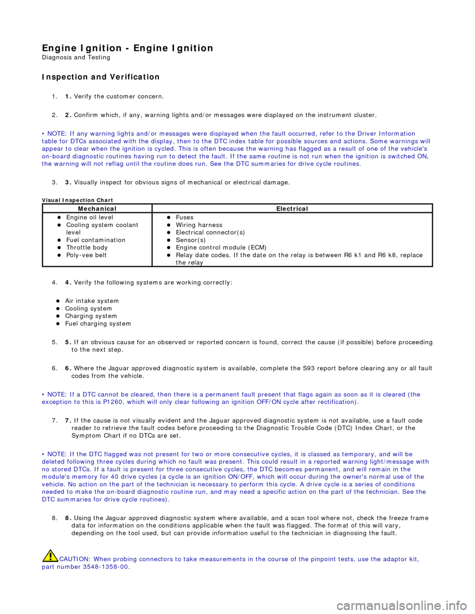
Engine Igni
tion -
Engine Ignition
D
iagnosis and Testing
I
nspection and Verification
1.
1. Veri
fy the customer concern.
2. 2. Confirm which, if any, warning li ghts and/or messages were displayed on the instrument cluster.
• NOTE: If any warning lights and/or me ssages were displayed when the fault occurred, refer to the Driver Information
table for DTCs associated with the display, then to the DTC index table for possible sources and actions. Some warnings will
appear to clear when the ignition is cycl ed. This is often because the warning has flagged as a resu lt of one of the vehicle's
on-board diagnostic routines having run to detect the fault. If the same routine is not run when the ignition is switched ON,
the warning will not reflag until the routine does run. See the DTC summaries for drive cycle routines.
3. 3. Visually inspect for obvious signs of mechanical or electrical damage.
V
isual Inspection Chart
4.
4. Veri
fy the following syst
ems are working correctly:
Air in
take system
Coo
ling system
Charging system
F
uel charging system
5. 5. If an obvious cause for an observed or reported concern is found, correct the cause (if possible) before proceeding
to the next step.
6. 6. Where the Jaguar approved diagnostic sy stem is available, complete the S93 report before clearing any or all fault
codes from the vehicle.
• NOTE: If a DTC cannot be cleared, then there is a permanent fault present that flag s again as soon as it is cleared (the
exception to this is P1260, which will only clear following an ignition OFF/ON cycle after rectification).
7. 7. If the cause is not visually evident and the Jaguar approv ed diagnostic system is not available, use a fault code
reader to retrieve the fault codes be fore proceeding to the Diagnostic Trou ble Code (DTC) Index Chart, or the
Symptom Chart if no DTCs are set.
• NOTE: If the DTC flagged was not present for two or more co nsecutive cycles, it is classed as temporary, and will be
deleted following three cycl es during which no fault was present. This could result in a reported wa rning light/message with
no stored DTCs. If a fault is present for three consecutive cycles, the DTC becomes permanent, and will remain in the
module's memory for 40 drive cycles (a cy cle is an ignition ON/OFF, which will occur during the owner's normal use of the
vehicle. No action on the part of the technician is necessary to perform this cycle. A drive cycle is a series of conditions
needed to make the on-board diagnostic ro utine run, and may need a specific action on the part of the technician. See the
DTC summaries for driv e cycle routines).
8. 8. Using the Jaguar approved diagnostic system where available, and a scan tool where not, check the freeze frame
data for information on the conditions applicable when the fault was flagged. The format of this will vary,
depending on the tool used, but can pr ovide information useful to the technician in diagnosing the fault.
CAUTION: When probing connectors to take measurements in the course of the pinpoint tests, use the adaptor kit,
part number 3548-1358-00.
MechanicalElectrical
Engi
ne oil level
Coo
ling system coolant
level
Fuel contamination
Throttle body Poly
-vee belt
F
uses
W
iring harness
E
lectrical connector(s)
Sens
or(s)
Engine
control module (ECM)
Relay date codes.
If the date on the relay is between R6 k1 and R6 k8, replace
the relay
Page 1079 of 2490

F
or evaporative emissions components,
REFER to: Evaporative Emissions
(30
3-13
Evaporative Emissions, Diagnosis and Testing).
For ECT sensor tests,
REFER to: Electronic Engine Controls
(30
3-14
Electronic Engine Co ntrols, Diagnosis and
Testing).
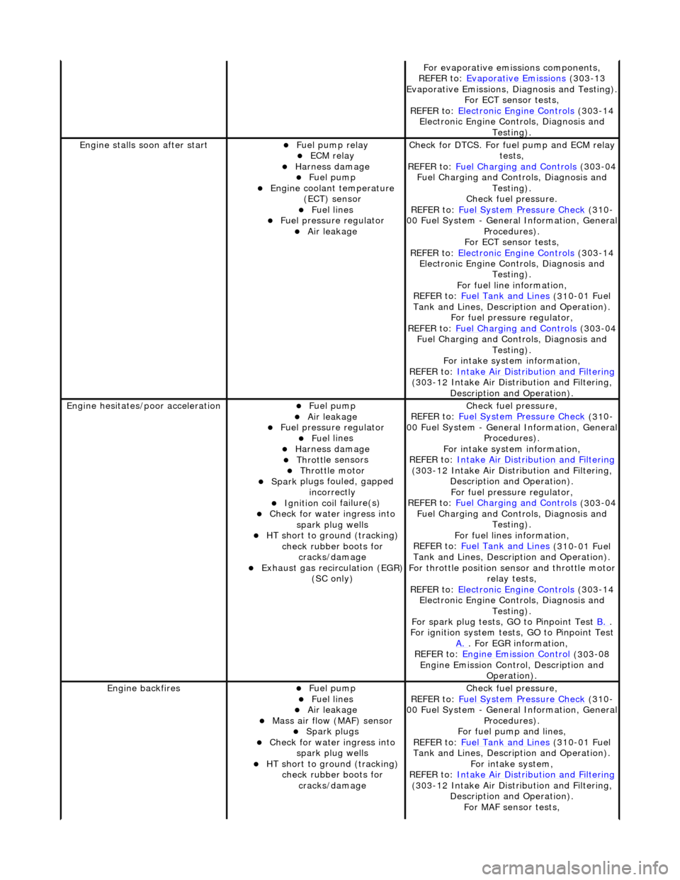
Engine stalls
soon after start
F
uel pump relay
ECM relay
Harness damage Fue
l pump
Engine coolan
t temperature
(ECT) sensor
Fue
l lines
F
uel pressure regulator
Air leakage
Check f
or DTCS. For fuel pump and ECM relay
tests,
REFER to: Fuel Charging and Controls
(30
3-04
Fuel Charging and Controls, Diagnosis and Testing).
Check fuel pressure.
REFER to: Fuel System Pressure Check
(31
0-
00 Fuel System - Genera l Information, General
Procedures).
For ECT sensor tests,
REFER to: Electronic Engine Controls
(30
3-14
Electronic Engine Co ntrols, Diagnosis and
Testing).
For fuel line information,
REFER to: Fuel Tank and Lines
(31
0-01 Fuel
Tank and Lines, Description and Operation).
For fuel pressure regulator,
REFER to: Fuel Charging and Controls
(30
3-04
Fuel Charging and Controls, Diagnosis and Testing).
For intake system information,
REFER to: Intake Air Distribution and Filtering
(30
3-12 Intake Air Distribution and Filtering,
Description and Operation).
Engine hesi
tates/poor acceleration
Fue
l pump
Air leakage
F
uel pressure regulator
Fue
l lines
Harness damage Throttl
e sensors
Throttl
e motor
Spark
plugs fouled, gapped
incorrectly
Ignition coil
failure(s)
Check f
or water ingress into
spark plug wells
HT sho
rt to ground (tracking)
check rubber boots for cracks/damage
Exhaus
t gas recirculation (EGR)
(SC only)
Chec
k fuel pressure,
REFER to: Fuel System Pressure Check
(31
0-
00 Fuel System - Genera l Information, General
Procedures).
For intake system information,
REFER to: Intake Air Distribution and Filtering
(30
3-12 Intake Air Distribution and Filtering,
Description and Operation). For fuel pressure regulator,
REFER to: Fuel Charging and Controls
(30
3-04
Fuel Charging and Controls, Diagnosis and Testing).
For fuel lines information,
REFER to: Fuel Tank and Lines
(31
0-01 Fuel
Tank and Lines, Description and Operation).
For throttle position se nsor and throttle motor
relay tests,
REFER to: Electronic Engine Controls
(30
3-14
Electronic Engine Co ntrols, Diagnosis and
Testing).
For spark plug tests, GO to Pinpoint Test B.
.
For ign
ition system tests, GO to Pinpoint Test
A.
. F
or EGR information,
REFER to: Engine Emission Control
(30
3-08
Engine Emission Cont rol, Description and
Operation).
Engine ba
ckfires
Fue
l pump
Fue
l lines
Air leakage
Mass ai
r flow (MAF) sensor
Spark plugs
Check f
or water ingress into
spark plug wells
HT sho
rt to ground (tracking)
check rubber boots for cracks/damage
Chec
k fuel pressure,
REFER to: Fuel System Pressure Check
(31
0-
00 Fuel System - Genera l Information, General
Procedures).
For fuel pump and lines,
REFER to: Fuel Tank and Lines
(31
0-01 Fuel
Tank and Lines, Description and Operation).
For intake system,
REFER to: Intake Air Distribution and Filtering
(30
3-12 Intake Air Distribution and Filtering,
Description and Operation). For MAF sensor tests,