Page 875 of 2490

Engine - Valve Springs LH
In-vehicle Repair
Removal
Special Tool(s)
Valve spring compressor
303-252 1. Open the engine compartment and fit paintwork protection
sheets.
2. Set the engine compartment cover to the service access
position.
3. Disconnect the batt ery ground cable.
Remove the battery cover.
4. Remove the Timing Co ver. Refer to Operation 12.65.01 in this
Section. This operation includes draining the coolant from the
radiator and removing the cam covers.
5. Remove the Inlet Manifold. Refer to Operation 30.15.01 in this
Section. This operation includes depressurising the fuel system
and removing the throttle housing.
6. Remove the Cylinder Head an d Gasket. Refer to Operation
12.29.02 in this Section.
7. Remove the valve collets from the first valve.
1. Fit the valve spring compressor 303 - 252 to the relevant spring.
2. Compress the spring and remove the collets.
8. Remove the valve spring.
Remove the valve spring compressor 303 - 252.
1. Remove the valve collar.
2. Remove the valve spring.
Page 876 of 2490

Installation
9. Repeat the instructions for each valve spring to be removed.
10. Clean all relevant components.
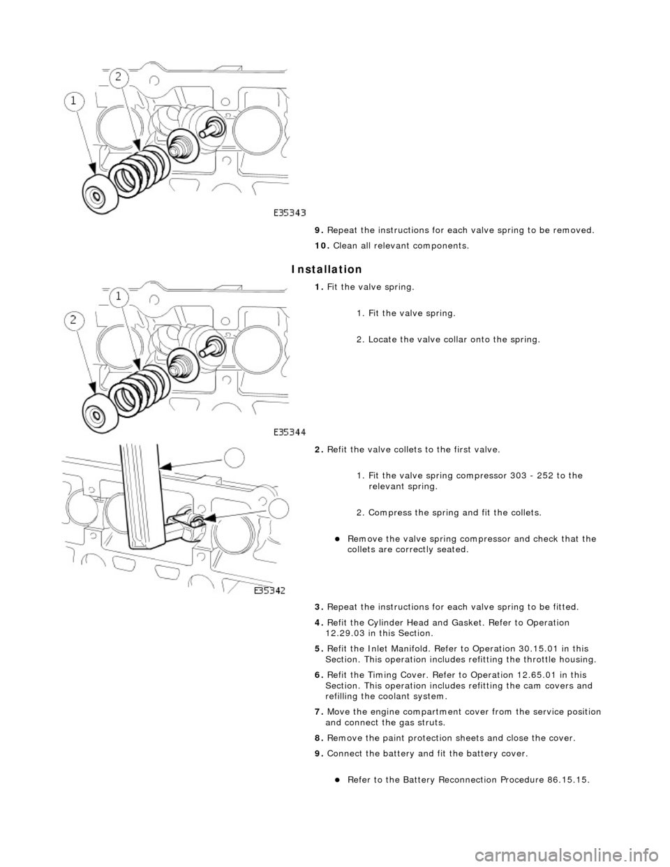
1. Fit the valve spring.
1. Fit the valve spring.
2. Locate the valve collar onto the spring.
2. Refit the valve collets to the first valve.
1. Fit the valve spring compressor 303 - 252 to the relevant spring.
2. Compress the spring and fit the collets.
Remove the valve spring compressor and check that the
collets are correctly seated.
3. Repeat the instructions for each valve spring to be fitted.
4. Refit the Cylinder Head and Gasket. Refer to Operation
12.29.03 in this Section.
5. Refit the Inlet Manifold. Refer to Operation 30.15.01 in this
Section. This operation includes refitting the throttle housing.
6. Refit the Timing Cover. Refer to Operation 12.65.01 in this
Section. This operation includes refitting the cam covers and
refilling the coolant system.
7. Move the engine compartment co ver from the service position
and connect the gas struts.
8. Remove the paint protection sheets and close the cover.
9. Connect the battery and fit the battery cover.
Refer to the Battery Reconnection Procedure 86.15.15.
Page 877 of 2490

Engine - Valve Springs RH
In-vehicle Repair
Removal
Special Tool(s)
Valve spring compressor
303-252 1. Open the engine compartment and fit paintwork protection
sheets.
2. Set the engine compartment cover to the service access
position.
3. Disconnect the batt ery ground cable.
Remove the battery cover.
4. Remove the Timing Co ver. Refer to Operation 12.65.01 in this
Section. This operation includes draining the coolant from the
radiator and removing the cam covers.
5. Remove the Inlet Manifold. Refer to Operation 30.15.01 in this
Section. This operation includes depressurising the fuel system
and removing the throttle housing.
6. Remove the Cylinder Head an d Gasket. Refer to Operation
12.29.03 in this Section.
7. Remove the valve collets from the first valve.
1. Fit the valve spring compressor 303 - 252 to the relevant spring.
2. Compress the spring and remove the collets.
8. Remove the valve spring.
Remove the valve spring compressor 303 - 252.
1. Remove the valve collar.
2. Remove the valve spring.
Page 878 of 2490

Installation
9. Repeat the instructions for each valve spring to be removed.
10. Clean all relevant components.
1. Fit the valve spring.
1. Fit the valve spring.
2. Locate the valve collar onto the spring.
2. Refit the valve collets to the first valve.
1. Fit the valve spring compressor 303 - 252 to the relevant spring.
2. Compress the spring and fit the collets.
Remove the valve spring compressor and check that the
collets are correctly seated.
3. Repeat the instructions for each valve spring to be fitted.
4. Refit the Cylinder Head and Gasket. Refer to Operation
12.29.03 in this Section.
5. Refit the Inlet Manifold. Refer to Operation 30.15.01 in this
Section. This operation includes refitting the throttle housing.
6. Refit the Timing Cover. Refer to Operation 12.65.01 in this
Section. This operation includes refitting the cam covers and
refilling the coolant system.
7. Move the engine compartment co ver from the service position
and connect the gas struts.
8. Remove the paint protection sheets and close the cover.
9. Connect the battery and fit the battery cover.
Refer to the Battery Reconnection Procedure 86.15.15.
Page 898 of 2490

ENSURE THAT ALL FIRE PREVENTION PROCEDURES ARE ACTIVE.
BEFORE PROCEEDING, IT IS ESSENTIAL THAT THE WARNING NOTES GIVEN IN SECTION 100-00 (UNDER THE
HEADING 'SAFETY PRECAUTIONS') ARE READ AND UNDERSTOOD.
9. Depressurise the fuel system.
Ensure that the ignition is switched off and remove the
valve cap from the fuel cross-over pipe. Place a cloth
under the valve to collect any spillage.
Place a closed container, su itable for collecting fuel,
adjacent to the vehicle. Remove the lid.
10. Connect the fuel injection pressure test equipment 310 - 058
(or other suitable type). Insert the drain / bleed tube into the
fuel container. Follow the ma nufacturer's instructions and
depressurise the fuel system.
11. Store the drained fuel safely and ensure that the lid is closed
securely. Remove the equipmen t and discard the cloth from
beneath the valve. Refit the valve cap.
12. Disconnect the breather pipe from the A-Bank camshaft
cover.
1. Disconnect the breather pipe from the stub pipe.
2. Remove and discard the O-ring seal from the breather
pipe.
13. Disconnect the air flow meter multi-plug.
14. Cut and remove the strap which secures the vacuum pipe to
the induction elbow.
15. Disconnect the intake tube from the throttle body.
1. Remove the two bolts which secure the intake tube to the throttle body.
2. Disconnect the intake tube from the throttle body.
Page 899 of 2490
16. Disconnect the air cleaner cover.
Remove the five clips which se cure the air cleaner cover.
17. Remove the intake tube / air flow meter / air cleaner cover
assembly.
1. Remove the intake tube / air flow meter / air cleaner
cover assembly.
2. Remove and discard the ru bber seal; air intake tube
to throttle body.
18. Remove the centre trim panel from the engine compartment.
1. Remove the left hand side enclosure panel.
2. Remove the centre trim panel.
19. Release the hoses (Quick Fit connections) from the expansion
tank, using 303 - 623.
1. Release the hose, expansion tank to thermostat housing (coolant outlet pipe on supercharged
engines).
Page 907 of 2490

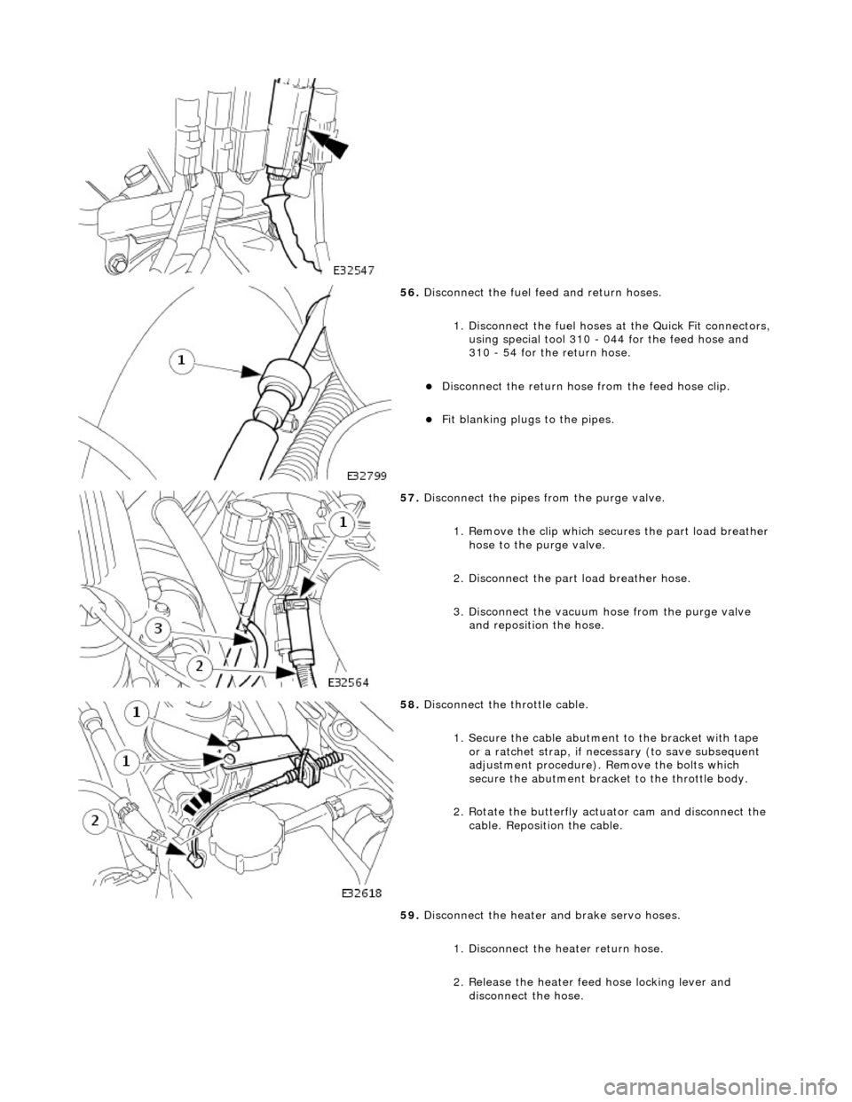
56. Disconnect the fuel feed and return hoses.
1. Disconnect the fuel hoses at the Quick Fit connectors,
using special tool 310 - 044 for the feed hose and
310 - 54 for the return hose.
Disconnect the return hose from the feed hose clip.
Fit blanking plugs to the pipes.
57. Disconnect the pipes from the purge valve.
1. Remove the clip which secu res the part load breather
hose to the purge valve.
2. Disconnect the part load breather hose.
3. Disconnect the vacuum hose from the purge valve and reposition the hose.
58. Disconnect the throttle cable.
1. Secure the cable abutment to the bracket with tape or a ratchet strap, if nece ssary (to save subsequent
adjustment procedure). Remove the bolts which
secure the abutment bracke t to the throttle body.
2. Rotate the butterfly actuator cam and disconnect the cable. Reposition the cable.
59. Disconnect the heater and brake servo hoses.
1. Disconnect the he ater return hose.
2. Release the heater feed hose locking lever and
disconnect the hose.
Page 916 of 2490
3. Conne
ct the brake servo hose.
26. Conne
ct the P.I. harness to the engine management
harness.
1. Reposition the engi ne management harness
connector to the bracket.
2. Fit the nut which secures the engine management harness connector to the mounting bracket.
3. Connect the connectors.
4. Fit the bolt which secures the P.I. harness connector to the engine management harness.
27 . Conne
ct the transmission rotary
switch harness connector.
Re
position and connect the harness.
28 . Con
nect the throttle cable.
1. Fit the bolts which secure the abutment bracket to the throttle body. Tighten to 4-6 Nm.
2. Rotate the butterfly actuator cam and connect the cable. Reposition the cable into the cam.
Re
move any tape or plastic
strap which was fitted when
disconnecting the cable abutment.
29. Connect the pipes to the purge valve.
1. Connect the part load breather hose.
2. Fit the clip which secures the part load breather hose
to the purge valve.