1998 ISUZU TROOPER wheel
[x] Cancel search: wheelPage 312 of 3573

2A – 10 POWER STEERING
POWER STEERING SYSTEM TEST
TEST PROCEDURE
Test of fluid pressure in the power steering system
is performed to determine whether or not the oil
pump and power steering unit are functioning
normally.
The power steering system test is method used to
identify and isolate hydraulic circuit difficulties.
Prior to performing this test, the following
inspections and corrections, if necessary, must be
made.
INSPECT
•Pump reservoir for proper fluid level.
•Pump belt for proper tension.
•Pump driver pulley condition.
1. Place a container under the pump to catch the
fluid when disconnecting or connecting the
hoses.
2. With the engine NOT running , disconnect the
pressure hose at the power steering pump and
install Power Steering tester.
The gage must be between the shutoff valve
and pump. Open the shutoff valve.
Tester: 5-8840-0135-0 (J-29877-A)
Adapter: 5-8840-2297-0 (For 6VD1, 6VE1, 4JX1)
5-8840-0136-0 (For 4JG2)3. Check the fluid level. Fill the reservoir with
power steering fluid, to the “Full” mark. Start
the engine then turn the steering wheel and
momentarily hold it against a stop. Turn off
and check the connections at tester for leakage.
4. Bleed the system. Refer to “Bleeding the
Power Steering System” in this section.
5. Start the engine and check the pump fluid
level. Add power steering fluid if required.
When the engine is at normal operating
temperature, increase engine speed to 1500
rpm.
CAUTION:
Do not leave shutoff valve fully closed for more
than 5 seconds, as the pump could become
damaged internally.
6. Fully close the shutoff valve. Record the
highest pressures.
•If the pressure recorded is within 9300-9800
kPa (1350-1420 psi) For 6VD1, 6VE1, and
9800-10300 kPa (100-105 kg/cm
2/ 1420-1490
psi) For 4JG2, 4JX1, the pump is functioning
within its specifications.
•If the pressure recorded is higher than 9800
kPa (1420 psi) For 6VD1, 6VE1, and 10300
kPa (105 kg/cm
2/ 1490 psi) For 4JG2, 4JX1,
the valve in the pump is defective.
Page 313 of 3573
POWER STEERING 2A – 11
•If the pressure recorded is lower than 9300
kPa (1350 psi) For 6VD1, 6VE1, and 9800 kPa
(100 kg/cm
2/ 1420 psi) For 4JG2, 4JX1, the
valve or the rotating group in the pump is
defective.
7. If the pump pressure are within specifications,
leave the valve open and turn (or have
someone else turn) the steering wheel fully in
both directions. Record the highest pressures
and compare with the maximum pump
pressure recorded in step 6. If this pressure cannot be built in either (or one) side of the
power steering gear, the power steering gear is
leaking internally and must be disassembled
and repaired.
8. Shut the engine off, remove the testing gage,
reconnect the pressure hose, check the fluid
level and make the needed repairs.
9. If the problem still exists, the steering and front
suspension must be thoroughly examined.
Page 314 of 3573
BLEEDING THE POWER
STEERING SYSTEM
When a power steering pump or gear has been
installed, or an oil line has been disconnected, the
air that has entered the system must be bled out
before the vehicle is operated. If air is allowed to
remain in the power steering fluid system, noisy
and unsatisfactory operation of the system may
result.
BLEEDING PROCEDURE
When bleeding the system, and any time fluid is
added to the power steering system, be sure to use
only power steering fluid as specified in
“MAINTENANCE AND LUBRICATION” in section
0B.
1. Fill the pump fluid reservoir to the proper
level and let the fluid settle for at least two
minutes.
2. Start the engine and let it run for a few
seconds.
Do not turn the steering wheel. Then turn the
engine off.
3. Add fluid if necessary.
4. Repeat the above procedure until the fluid
level remains constant after running the
engine.
5. Raise the front end of the vehicle so that the
wheels are off the ground.
6. Start the engine. Slowly turn the steering
wheel right and left, lightly contacting the
wheel stops.
7. Add power steering fluid if necessary.
8. Bring down the vehicle, set the steering wheel
at the straight forward position after turning it
to its full steer positions 2 or 3 times, and stop
the engine.
9. Stop the engine. Check the fluid level and
refill as required.
10. If the fluid is extremely foamy, allow the
vehicle to stand a few minutes and repeat the
above procedure.
INSPECT
•Belt for tightness.
•Pulley for looseness or damage. The pulley
should not wobble with the engine running.
•Make sure that hose and pipes are properly
fitted.
•Fluid level and fill to the proper level.
FLUSHING THE POWER
STEERING SYSTEM
1. Raise the front end of the vehicle off the
ground until the wheels are free to turn.
2. Remove the fluid return line at the reservoir
inlet connector and plug the connector.
Position the line toward a large container to
catch the draining fluid.
3. While running the engine at idle, fill the
reservoir with new power steering fluid. Turn
the steering wheel in both directions. Do not
contact wheel stops or hold the wheel in a
corner, or fluid will stop and the pump will be
in pressure relief mode. A sudden overflow
from the reservoir may develop if the wheel is
held at a stop.
4. While refilling the reservoir, check the
draining fluid for contamination. If foreign
material is still evident, replace all lines,
disassemble and clean or replace the power
steering system components. Do not re-use
any drained power steering fluid.
5. Install all the lines and hoses. Fill the system
with new power steering fluid and bleed the
system as described in “Bleeding The Power
Steering System”. Operate the engine for
about 15 minutes. 2A – 12 POWER STEERING
ON-VEHICLE SERVICE
Page 344 of 3573

2A – 42 STEERING LINKAGE
GENERAL DESCRIPTION
Center track rod assembly
Rod end, outerTrack rodRod end, inner
Relay lever These steps are based on the LHD model.
Outer track rod assembly
Pitman arm
The steering linkage consists of a pitman arm,
relay lever, center track rod and two adjustable
outer track rods.
When the steering wheel is turned, the gear rotates
the pitman arm which forces the center track rod to
one side. The outer track rods, connected to the
center track rod by ball studs, transfer the steering
force to the wheels. The outer track rods are
adjustable and are used for toe-in adjustments.
The center track rod is supported by the pitman
arm and relay lever. The relaylever pivots on a
support attached to the frame.The overall condition of the steering linkage affects
steering performance. If parts are bent, damaged,
worn or poorly lubricated, improper and possibly
dangerous steering action will result.
Whenever any steering linkage components are
repaired or replaced, check the steering geometry
and front end alignment. Refer to Front End
Alignment (Sec. 3A).
433RW004
This illustration is based on the LHD model.
Page 349 of 3573
STEERING LINKAGE 2A – 47
REMOVAL
Preparation:
Remove wheel and tire assembly.
Refer to “Wheels and Tires” in section 3E.
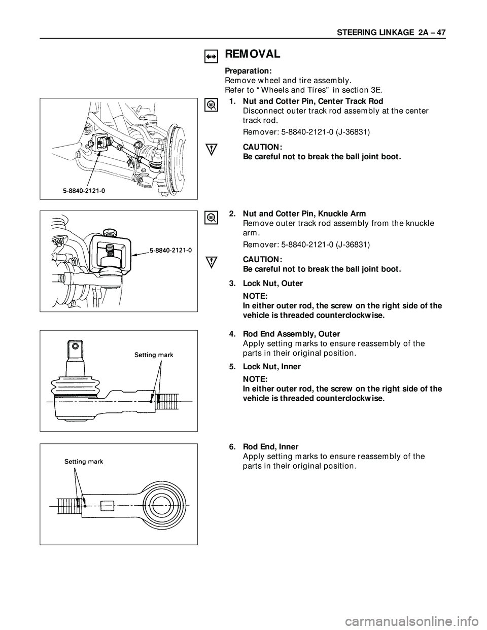
1. Nut and Cotter Pin, Center Track Rod
Disconnect outer track rod assembly at the center
track rod.
Remover: 5-8840-2121-0 (J-36831)
CAUTION:
Be careful not to break the ball joint boot.
2. Nut and Cotter Pin, Knuckle Arm
Remove outer track rod assembly from the knuckle
arm.
Remover: 5-8840-2121-0 (J-36831)
CAUTION:
Be careful not to break the ball joint boot.
3. Lock Nut, Outer
NOTE:
In either outer rod, the screw on the right side of the
vehicle is threaded counterclockwise.
6. Rod End, Inner
Apply setting marks to ensure reassembly of the
parts in their original position.
4. Rod End Assembly, Outer
Apply setting marks to ensure reassembly of the
parts in their original position.
5. Lock Nut, Inner
NOTE:
In either outer rod, the screw on the right side of the
vehicle is threaded counterclockwise.
Page 353 of 3573
SUPPLEMENTAL RESTRAINT SYSTEM STEERING WHEEL & COLUMN 2A – 51
SECTION 2A
SUPPLEMENTAL RESTRAINT SYSTEM
STEERING WHEEL & COLUMN
CAUTION:
When fasteners are removed, always reinstall them at the same location from which
they were removed. If a fastener needs to be replaced, use the correct part number
fastener for that application. If the correct part number fastener is not available, a
fastener of equal size and strength (or stronger) may be used. Fasteners that are not
reused, and those requiring thread locking compound, will be called out. The correct
torque value must be used when installing fasteners that require it. If the above
conditions are not followed, parts or system damage could result.
CONTENTS
PAGE
General Description ......................................................................................................... 2A – 52
On-Vehicle Service ........................................................................................................... 2A – 53
SRS Connectors ........................................................................................................... 2A – 53
Inflator Module Replacement ..................................................................................... 2A – 54
Steering Wheel Replacement ..................................................................................... 2A – 57
Combination Switch Replacement ............................................................................ 2A – 60
Lock Cylinder Replacement ........................................................................................ 2A – 64
Steering Column Replacement .................................................................................. 2A – 69
Page 354 of 3573
This steering wheel and column repair section
covers the Supplemental Restraint System (SRS)
steering column. The following repair procedures
are specific to SRS Components. When servicing a
vehicle equipped with Supplemental Restraint
System, pay close attention to all WARNINGS and
CAUTIONS.
For detailed explanation about SRS, refer to Section
9J "SUPPLEMENTAL RESTRAINT SYSTEM (SRS)"
of manual.
The steering column has three important features in
addition to the steering function:
1. The column is energy absorbing, designed to
compress in a front-end collision to minimize
the possibility of injury to the driver of the
vehicle.
2. The ignition switch and lock are mounted
conveniently on the column.
3. With the column mounted lock, the ignition
and steering operation can be locked to
prevent theft of the vehicle.
The column may be disassembled and
reassembled. To insure the energy absorbing
action, it is important that the specified screws,
bolts and nuts be used only as designated and that
they are tightened to the specified torque.
When the column is removed from the vehicle, a
sharp blow on the end of steering shaft or shift
lever, leaning on the column assembly, or dropping
the assembly could shear or loosen the fasteners
that maintain column rigidity.
WARNING
THIS VEHICLE HAS A SUPPLEMENTAL RE-
STRAINT SYSTEM (SRS).REFER TO THE SRS
COMPONENT AND WIRING LOCATION VIEW
IN ORDER TO DETERMINE WHETHER YOU ARE
PERFORMING SERVICE ON OR NEAR THE SRS
COMPONENTS OR THE SRS WIRING. WHEN
YOU ARE PERFORMING SERVICE ON OR NEAR
THE SRS COMPONENTS OR THE SRS WIRING,
REFER TO THE SRS SERVICE INFORM ATION.
FAILURE TO FOLLOW WARNINGS COULD RE-
SULT IN POSSIBLE AIR BAG DEPLOYMENT,
PERSONAL INJURY, OR OTHERWISE UN-
NEEDED SRS SYSTEM REPAIRS.
SAFE HANDLING OF INFLATOR MODULES
REQUIRES FOLLOWING THE PROCEDURES
DESCRIBED BELOW FOR BOTH LIVE AND
DEPLOYED MODULES.
SAFETY PRECAUTIONS MUST BE FOLLOWEDWHEN HANDLING A DEPLOYED AIR BAG AS-
SEMBLY (AIR BAG). AFTER DEPLOYMENT,
THE AIR BAG ASSEMBLY (AIR BAG) SURFACE
MAY CONTAIN A SMALL AMOUNT OF SODIUM
HYDROXIDE, A BY-PRODUCT OF THE DEPLOY-
MENT REACTION, THAT IS IRRITATING TO THE
SKIN AND EYES.MOST OF THE POWDER ON
THE AIR BAG ASSEMBLY (AIR BAG) IS HARM-
LESS. AS A PRECAUTION, WEAR GLOVES
AND SAFETY GLASSES WHEN HANDLING A
DEPLOYED AIR BAG ASSEMBLY, AND WASH
YOUR HANDS WITH MILD SOAP AND WATER
AFTERWARDS.
WHEN CARRYING A LIVE AIR BAG ASSEMBLY,
MAKE SURE THE BAG AND TRIM COVER ARE
POINTED AWAY FROM YOU. NEVER CARRY
AN AIR BAG ASSEMBLY BY THE WIRES OR
CONNECTOR ON THE UNDERSIDE OF MODULE.
IN THE CASE OF AN ACCIDENTAL DEPLOY-
MENT, THE BAG WILL THEN DEPLOY WITH
MINIMAL CHANCE OF INJURY. WHEN PLACING
A LIVE AIR BAG ASSEMBLY ON A BENCH OR
OTHER SURFACE, ALWAYS FACE THE BAG AND
TRIM COVER UP, AWAY FROM THE SURFACE.
NEVER REST A STEERING COLUMN ASSEMBLY
ON THE STEERING WHEEL WITH THE AIR
BAG ASSEMBLY FACE DOWN AND COLUMN
VERTICAL.THIS IS NECESSARY SO THAT A
FREE SPACE IS PROVIDED TO ALLOW THE AIR
BAG ASSEMBLY TO EXPAND IN THE UNLIKELY
EVENT OF ACCIDENTAL DEPLOYMENT. OTHER-
WISE, PERSONAL INJURY COULD RESULT.
TO AVOID DEPLOYMENT WHEN TROUBLE
SHOOTING THE SRS SYSTEM, DO NOT USE
ELECTRICAL TEST EQUIPMENT, SUCH AS
BATTERY-POWERED OR A/C-POWERED VOLT-
METER, OHMMETER, ETC., OR ANY TYPE OF
ELECTRICAL EQUIPMENT OTHER THAN SPECI-
FIED IN THIS MANUAL. DO NOT USE A NON-
POWERED PROBE-TYPE TESTER.
INSTRUCTIONS IN THIS MANUAL MUST BE
FOLLOWED CAREFULLY, OTHERWISE PER-
SONAL INJURY MAY RESULT. 2A – 52 SUPPLEMENTAL RESTRAINT SYSTEM STEERING WHEEL & COLUMN
GENERAL DESCRIPTION
Page 355 of 3573
SUPPLEMENTAL RESTRAINT SYSTEM STEERING WHEEL & COLUMN 2A – 53
ON-VEHICLE SERVICE
21
827RW035
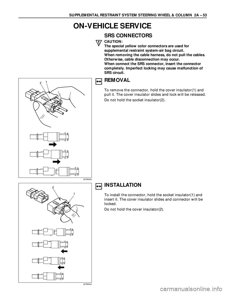
SRS CONNECTORS
CAUTION:
The special yellow color connectors are used for
supplemental restraint system-air bag circuit.
When removing the cable harness, do not pull the cables.
Otherwise, cable disconnection may occur.
When connect the SRS connector, insert the connector
completely. Imperfect locking may cause malfunction of
SRS circuit.
REMOVAL
To remove the connector, hold the cover insulator(1) and
pull it. The cover insulator slides and lock will be released.
Do not hold the socket insulator(2).
INSTALLATION
To install the connector, hold the socket insulator(1) and
insert it. The cover insulator slides and connector will be
locked.
Do not hold the cover insulator(2).
2
1
827RW034