Page 380 of 3573

2A – 78 SUPPLEMENTAL RESTRAINT SYSTEM STEERING WHEEL & COLUMN
INSTALLATION
3. Steering Wheel
Align the setting marks made when removing.
CAUTION:
Never apply force to the setting wheel in direction of the
shaft by using a hammer or other impact tools in an
attempt to install the steering wheel. The steering shaft is
designed as an energy absorbing unit.
2. Nut
Steering Wheel Nut Torque N·m (kg·m/lb·ft)
34 (3.5 / 25)
1. Center pad
Fit four projections of pad in holes on the steering
wheel side.
Tighten the screws on the lower side of the pad.
Center Pad Nut Torque N·m (kg·m/lb·in)
2.5 (0.25 / 21.7) 3. Steering Wheel
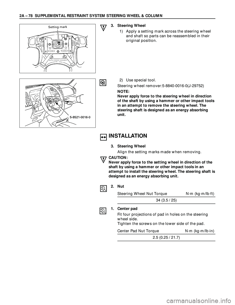
1) Apply a setting mark across the steering wheel
and shaft so parts can be reassembled in their
original position.
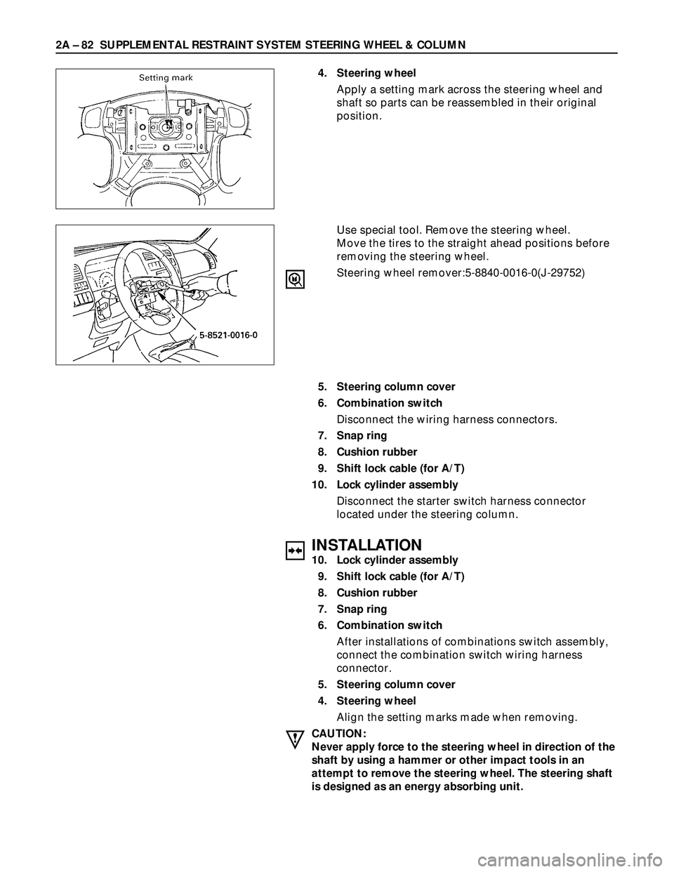
2) Use special tool.
Steering wheel remover:5-8840-0016-0(J-29752)
NOTE:
Never apply force to the steering wheel in direction
of the shaft by using a hammer or other impact tools
in an attempt to remove the steering wheel. The
steering shaft is designed as an energy absorbing
unit.
Page 381 of 3573
SUPPLEMENTAL RESTRAINT SYSTEM STEERING WHEEL & COLUMN 2A – 79
4
1 2
6
3
5 These steps are based on the LHD model.
Removal Steps
1. Front console assembly
2. Lower cluster assembly
3. Steering lower cover
4. Steering wheel
5. Steering column cover
6. Combination switch
Installation Steps
6. Combination switch
5. Steering column cover
4. Steering wheel
3. Steering lower cover
2. Lower cluster assembly
1. Front console assembly
REMOVAL
1. Front console assembly
1) Remove the transmission (for M/T) and transfer
control lever knob.
2) Disconnect the wiring harness connectors.
2. Lower cluster assembly
3. Steering lower cover
Remove the engine hood opening lever.
4. Steering wheel
Apply a setting mark across the steering wheel and
shaft so parts can be reassembled in their original
position.
COMBINATIONS SWITCH REPLACEMENT
431RW021
These steps are based on the LHD model.
Page 382 of 3573

2A – 80 SUPPLEMENTAL RESTRAINT SYSTEM STEERING WHEEL & COLUMN
INSTALLATION
6. Combination switch
After installations of combinations switch assembly,
connect the combination switch wiring harness
connector.
5. Steering column cover
4. Steering wheel
Align the setting marks made when removing.
CAUTION:
Never apply force to the setting wheel in direction of the
shaft by using a hammer or other impact tools in an
attempt to remove the steering wheel. The steering shaft
is designed as an energy absorbing unit.
Tighten the steering wheel fixing nut to the specified
torque.
Steering wheel Nut Torque N·m (kg·m/lb·ft)
34 (3.5 / 25)
3. Steering lower cover
Install the engine hood opening lever.
2. Lower cluster assembly
1. Front console assembly
Install the transmission (for M/T) and transfer control
lever knob.
Install the wiring harness connectors. Use special tool. Remove the steering wheel.
Move the tires to the straight ahead positions before
removing the steering wheel.
Steering wheel remover:5-8840-0016-0(J-29752)
CAUTION:
Never apply force to the steering wheel in direction of the
shaft by using a hammer or other impact tools in an
attempt to remove the steering wheel. The steering shaft
is designed as an energy absorbing unit.
5. Steering column cover
6. Combination switch
Disconnect the wiring harness connector.
Page 383 of 3573
SUPPLEMENTAL RESTRAINT SYSTEM STEERING WHEEL & COLUMN 2A – 81
These steps are based on the LHD model.
REMOVAL
1. Front console assembly
1) Remove the transmission (for M/T) and transfer
control lever knob.
2) Disconnect the wiring harness connectors.
2. Lower cluster assembly
3. Steering lower cover
Remove the engine hood opening lever.
LOCK CYLINDER REPLACEMENT
Removal Steps
1. Front console assembly
2. Lower cluster assembly
3. Steering lower cover
4. Steering wheel
5. Steering column cover
6. Combination switch
7. Snap ring
8. Cushion rubber
9. Shift lock cable (for A/T)
10. Lock cylinder assembly
Installation Steps
10. Lock cylinder assembly
9. Shift lock cable (for A/T)
8. Cushion rubber
7. Snap ring
6. Combination switch
5. Steering column cover
4. Steering wheel
3. Steering lower cover
2. Lower cluster assembly
1. Front console assembly
Page 384 of 3573

2A – 82 SUPPLEMENTAL RESTRAINT SYSTEM STEERING WHEEL & COLUMN
5. Steering column cover
6. Combination switch
Disconnect the wiring harness connectors.
7. Snap ring
8. Cushion rubber
9. Shift lock cable (for A/T)
10. Lock cylinder assembly
Disconnect the starter switch harness connector
located under the steering column.
INSTALLATION
10. Lock cylinder assembly
9. Shift lock cable (for A/T)
8. Cushion rubber
7. Snap ring
6. Combination switch
After installations of combinations switch assembly,
connect the combination switch wiring harness
connector.
5. Steering column cover
4. Steering wheel
Align the setting marks made when removing.
CAUTION:
Never apply force to the steering wheel in direction of the
shaft by using a hammer or other impact tools in an
attempt to remove the steering wheel. The steering shaft
is designed as an energy absorbing unit.4. Steering wheel
Apply a setting mark across the steering wheel and
shaft so parts can be reassembled in their original
position.
Use special tool. Remove the steering wheel.
Move the tires to the straight ahead positions before
removing the steering wheel.
Steering wheel remover:5-8840-0016-0(J-29752)
Page 385 of 3573
SUPPLEMENTAL RESTRAINT SYSTEM STEERING WHEEL & COLUMN 2A – 83
Tighten the steering wheel fixing nut to the specified
torque.
Steering wheel Nut Torque N·m (kg·m/lb·ft)
34 (3.5 / 25)
3. Steering lower cover
Install the engine hood opening lever.
2. Lower cluster assembly
1. Front console assembly
Connect the wiring harness connectors.
Install the transmission (for M/T) and transfer control
lever knob.
Page 386 of 3573
2A – 84 SUPPLEMENTAL RESTRAINT SYSTEM STEERING WHEEL & COLUMN
These steps are based on the LHD model.
REMOVAL
1. Front console assembly
Disconnect the transmission (for M/T) and transfer
control lever knob.
Disconnect the wiring harness connectors.
2. Lower cluster assembly
STEERING COLUMN REPLACEMENT
Removal Steps
1. Front console assembly
2. Lower cluster assembly
3. Steering lower cover
4. Steering wheel
5. Steering column cover
6. Combination switch
7. Snap ring
8. Cushion rubber
9. Shift lock cable (for A/T)
10. Lock cylinder assembly
11. Steering column assembly
Installation Steps
11. Steering column assembly
10. Lock cylinder assembly
9. Shift lock cable (for A/T)
8. Cushion rubber
7. Snap ring
6. Combination switch
5. Steering column cover
4. Steering wheel
3. Steering lower cover
2. Lower cluster assembly
1. Front console assembly
Page 387 of 3573
SUPPLEMENTAL RESTRAINT SYSTEM STEERING WHEEL & COLUMN 2A – 85
5. Steering column cover
6. Combination switch
Disconnect the wiring harness connectors.
7. Snap ring
8. Cushion rubber
9. Shift lock cable (for A/T)
10. Lock cylinder assembly
Disconnect the starter switch harness connector
located under the steering column.
11. Steering column assembly
Apply a setting mark across the universal joint and
steering shaft to reassembly the parts in their original
position.
NOTE:
A setting mark can be easily made if the shaft is
withdrawn a little by loosening the steering shaft
universal joint. 3. Steering lower cover
Remove the engine hood opening lever.
4. Steering wheel
Apply a setting mark across the steering wheel and
shaft so parts can be reassembled in their original
position.
Use special tool. Remove the steering wheel.
Move the tires to the straight ahead positions before
removing the steering wheel.
Steering wheel remover:5-8840-0016-0(J-29752)