Page 1052 of 1681
Compressor
a
a
Clutch Overhaul (cont'dl
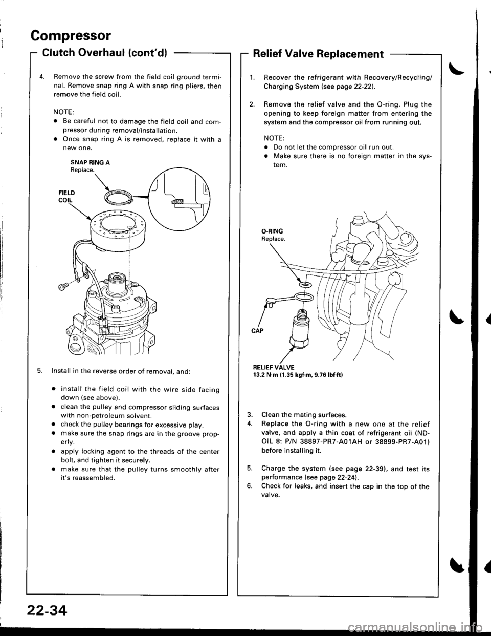
Remove the screw from the field coil ground termi,
nal. Remove snap ring A with snap ring pliers, then
remove the field coil.
. Be careful not to damage the field coil and com-presso. during removal/installation.
. Once snap ring A is removed, replace it with a
SNAP RING AReplace.
5. Install in the reverse order of removal, andl
install the field coil with the wire side facing
down (see above).
clean the pulley and compressor sliding surfaceswith non-petroleum solvent.
check the pulley bearings for excessive play.
make sure the snap rings are in the groove prop-
efly.
apply locking agent to the threads of the center
bolt, and tighten it securely.
make sure that the pulley turns smoothly after
it's reassembled.
Relief Valve Replacement
Recover the refrigerant with Recovery/Recycling/
Charging System lsee page 22-221.
Remove the relief valve and the O-ring. Plug the
opening to keep foreign matter from entering the
system and the compressor oil from running out,
NOTE:
. Do not let the compressor oil run out.
. Make sure there is no foreign matter in the sys-
tem.
RELIEF VALVE13.2 N.m (1.35 kgf.m,9.76lbtft)
3. Clean the mating surfaces.
4. Replace the O-ring with a new one at the relief
valve, and apply a thin coat of refrigerant oil (ND-
OIL 8: P/N 38897-PR7-A01AH or 38899-PR7-A01)
before installing it.
5. Charge the system (see page 22-39), and test itsperformance (see page 22-241.
6. Check for leaks, and insert the cap in the top of the
FIELD
t\I lu
B _t_:---\-lr
\,/
22-34
Page 1053 of 1681
J
A/G Compressor Belt
Replacement
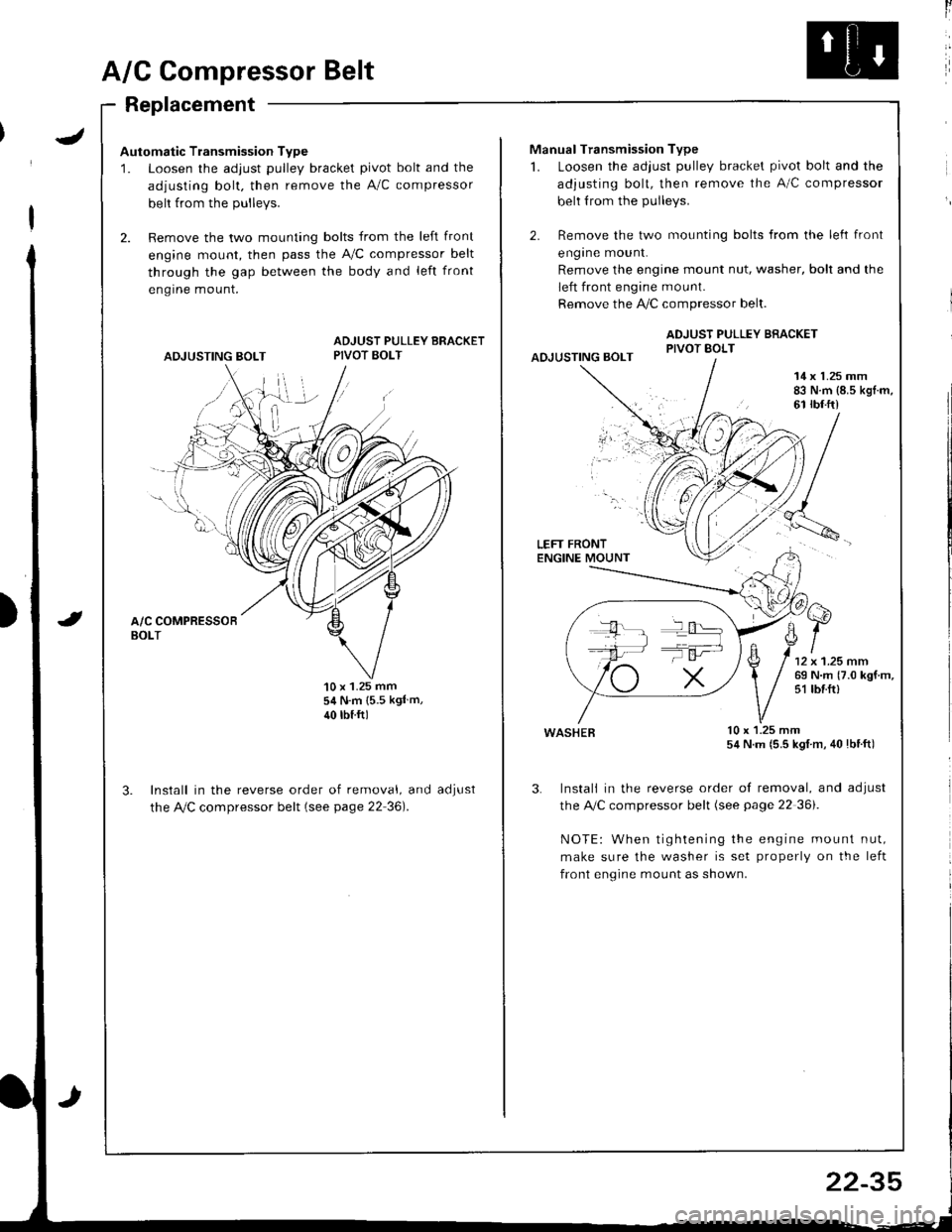
Automatic Transmission Type
1. Loosen the adjust pulley bracket pivot bolt and the
adjusting bolt. then remove the A/C compressor
belt from the Dullevs.
2. Remove the two mounting bolts from the left front
engine mount, then pass the A,/C compressor belt
through the gap between the body and left front
engrne mount.
ADJUSTING BOLT
ADJUST PULLEY BRACKETPIVOT BOLT
'10 x 1.25 mm54 N.m {5.5 kgl m,
40 rbtftl
Install in the reverse order of removal, and
the Ay'C compressor belt (see page 22 36).
aoJUsI
ll
Manual Transmission Type
1. Loosen the adjust pulley bracket pivot bolt and the
adjusting bolt, then remove the A/C compressor
belt from the pulleys.
2. Remove the two mounting bolts from the left front
engrne mount.
Remove the engine mount nut, washer, bolt and the
left front engine mount.
Remove the !i/C compressor belt.
ADJUST PULLEY BRACKETPIVOT BOLTAOJUSTING BOLT
14 x 1.25 mm83 N.m {8.5 kgl.m,61 rbf.ft)
LEFT FRONTENGINE MOUNT
wasHEB lu x l.z5 mm54 N.m (5.5 kgl m, 40lbtft)
3. Instali in the reverse order of removal, and adjust
the A,/C compressor belt (see page 22 36i.
NOTE: When tightening the engine mount nut,
make sure the washer is set properly on the left
front engine mount as shown.
T':
22-35
Page 1054 of 1681
A/C Compressor Belt
Adiustment
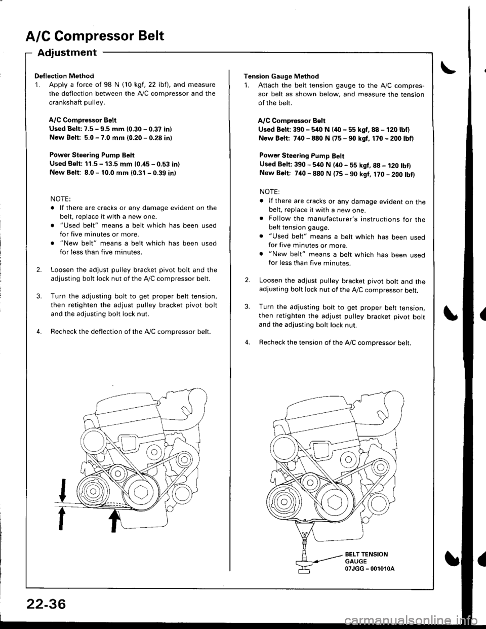
Dellection Method
1. Apply a force of 98 N i10 kgf, 22 lbf), and measure
the deflection between the A,/C compressor and the
crankshaft pullev.
A/C Compressor Belt
Used Belt: 7.5 - 9.5 mm (0.30 - 0.37 in)
New Beli: 5.0 - 7.0 mm (0.20 - 0.28 in)
Power Steering Pump Belt
Used Bslt: 11.5 - 13.5 mm (0.i15 - 0.53 in)
New Belt: 8.0 - 10.0 mm (0.31 - 0.39 in)
NOTE:
. lf there are cracks or any damage evident on the
belt, replace it with a new one.
. "Used belt" means a belt which has been used
for five minutes or more.
. "New belt" means a belt which has been used
for less than five minutes.
Loosen the adjust pulley bracket pivot bolt and the
adjusting bolt lock nut of the lVC compressor belt.
Turn the adjusting bolt to get proper belt tension,
then retighten the adjust pulley bracket pivot bolt
and the adjusting bolt lock nut.
Recheck the deflection of the Ay'C compressor belt.
22-36
Tension Gauge Method
1. Attach the belt tension gauge to the Ay'C compres-
sor belt as shown below, and measure the tension
of the belt.
A/C Comprossor Belt
Used Belt: 390 - 5/rc N (4O - 55 kgf. 88 - 120 lbf)
New Bslt: 7,10 - 880 N (75 - 90 kgf, 170 - 200 lbf)
Power Steering Pump Belt
Used Belt: 390 - 540 N (ito - 55 kgl, g8 - i20 tbtlNew Belt: 740 - 880 N (75 - 90 kgt, 170 - 200 tbtl
NOTE:
. lf there are cracks or any damage evident on thebelt, replace it with a new one.. Follow the manufacturer's instructions for thebelt tension gauge.
. "Used belt" means a belt which has been usedfor five minutes or more.. "New belt" means a belt which has been usedfor less than five minutes.
Loosen the adjust pulley bracket pivot bolt and theadjusting bolt lock nut of the A,/C compressor belt.
Turn the adjusting bolt to get proper belt tension,then retighten the adjust pulley bracket pivot boltand the adjusting bolt lock nut.
Recheck the tension of the A,/C compressor belt.
3.
BELT TENSIONGAUGE07JGG - 0010'l0a
Page 1064 of 1681
Relay and Control Unit Locations
Engine Compartment
ABS PUMP MOTORRELAY
FAN RELAY
UNDER.HOOD AB{iFUSE/RELAY BOXIKG mod.ll
A/C COMPRESSORCLUTCH RELAYRADIATORFAN BELAY
UNDER.H(X)DFUSE/RELAY BOX
A&S MODULAUNIT
UNDER.HOOD ABII FUSE,/RELAY BOX {KE modoll
----ar:l
--r: u
D
tr
L]
ABS PUMP MOTOR
23-7
Page 1071 of 1681
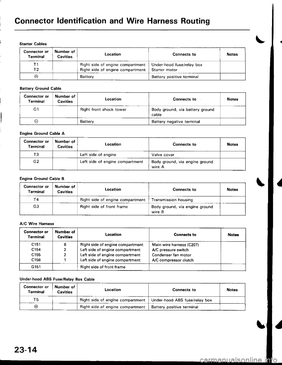
Connector ldentification and Wire Harness Routing
Starter Cables
Connectol ot
Terminal
Numbel of
CavitiesLocationConnects toNotes
Tl
r2
Right side of engine compartment
Right side oI engine compartment
Under-hood Iuse/relay box
Starter motor
oBatteryBattery positive terminal
Battely Ground Cable
Connector ol
Terminal
Numbel of
CavitiesLocationConnects toNotes
Right lront shock towerBody ground, via battery ground
caore
oBatteryBattery negative terminal
Engine Ground Cable A
Connector ol
Terminal
Number ol
CavitiesLocationConnects toNotes
T3Left side of engineValve cover
c2Left side oI engine compartmentBody ground. via engine ground
Engine Ground Cable B
Connector ol
Terminal
Numbel of
CavitiesLocationConnects toNot€s
r4Right side of engine compartmentTransmission housing
Right side of front frameBody ground, via engine ground
wire B
A/C Wire Harness
Connector or
Terminal
Number of
CavitiesLocationConnects toNotos
c 151
cl54
c156
8
2,l
Righr side of engine compartment
Left side of engine companment
Left side of engine compartment
Left side of engine compartment
Main wire harness (C207)
A,/C pressure switch
Condenser fan motor
ly'C compressor clutch
Right side of front frame
Under-hood ABS Fuse/Relav Box Cable
Connector or
Telminal
Number of
CavitiesLocationConnects toNotes
T5Right side o'f engine compartmentUnderhood ABS fuse/relay box
@Right side oI engine compaftmentBattery positive terminal
23-14
Page 1110 of 1681
J
)1 -
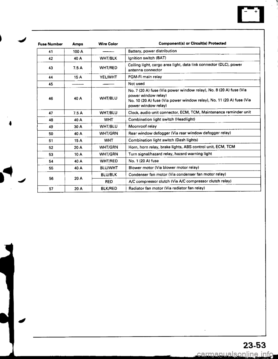
Fuso NumborAmpsWir€ ColorComponent(s) or Circuh(rl Protastcd
41100 ABattery. power distribution
4240AWHT/BLKlgnition switch (BAT)
437.5 AWHT/REDCeiling light, cargo area light, data link connector (DLCl, power
antenna connector
44't5 AYEL/WHTPGM-Fl main relay
45Not used
4640AWHT/8LU
No. 7 (20 A) fuse (Via power window relay), No. 8 (20 A) tuse (Via
power window relay)
No. 10 (20 A) fuse (Via power window relay), No. 11 (20 A) fuse (Via
power window relay)
417.5 AWHT/BLUClock,8udio unit connector, ECM, TCM, Maint€nance reminder unit
4840AWHTCombination light switch (Headlight)
4930AWHT/BLUMoonroof relay
5040AWHT/GRNRear window defogger {Via rear window defogger relay)
51154WHTCombination light switch (Dash lights)
20AWHT/GRNHorn, horn relay, brake lights, AgS control unit, ECM, TCM
10AWHT/GRNTurn signal/hazard relay, hazard warning light
5440AWHT/flEDNo. 1 (20 A) fuse
40ABLU/WHTBlower motor (Via blower motor relsy)
56204BLU/BLKCondenser fan motor (Via condenser {an motor relay)
REDA,/C compressor clutch (via Ay'c comp.essor clutch relay)
57204BLVREDRadiator f8n motor (Via radiator fan relay)
23-53
Page 1112 of 1681
\
I
UNOER HOOD FUSE/RELAY BOX
t
{
fr
wHr _+> HtXl!;%,'$1r.,',"' *,
F.-wr cn,r _l9> l,)ooll;%,r$lrr. rr,or ro,
*,,'orn. ---$ H?!!;oA%iu'n"*"o'
wHr -+ &?Tll:11$ uo""* "*
N0.17 (7.5A)FUSE(Fiom page 23 56)
V
L r,*,rr,
**, orn N u-NoEF DASF FlrsE RE'AY Boxt'/' I aaaqe zJ''L
BLUA/VHI - B ower motor
"*-f_
oro,G40l
BLU/YEL -'ncthermoslal(viadiode)
8LU/BLK - Condenser lan molor
,JC compressor clulch
BLKRED _ €CM
BLKRED - Radiatorian molor
GFN- EcMl- P36,r1ot 1"n t'n '"n
(cont'd)
23-55
_-_ _-.-
t)
Page 1126 of 1681
1
I
PowerRelays
RelayTest
JNOTE: See page 23-194 for turn signal/hazard relay
input test.
Normally.open type:
fWC2i
1. Check for continuitv between the terminals.
. There should be continuity between the A and B
terminals when power and ground are connect-
ed to the C and D terminals.
. There should be no continuity between the A
and B terminals when power is disconnected.
<2
F;Z
,,A
/ l'El--E \
ey
Normally-opon type:
'1. Check continuity between relay terminals.
. There should be continuity between the A and C
terminals when power and ground are connect-
ed to the B and D terminals.
o There should be no continuitv when oower is
disconnacted,
o Power window relay
. Radiator fan relay
. Condenser fan relay
. AVC compressor clutch relay
Typel:
c
I Blower motor relay
. Rear window defogger relay
Typel:
Terminal
P";(c5t--__\B
Disconnected
Connectedoo
Terminal
P"*"r(B5-lc
Connectedoo
Disconnected