Page 1019 of 1681
Air Gonditioning
+Evaporator
Repf acement .........22-26
Overhauf ................22-27
Compressor
Description ............22-28
lf lustrated f ndex ............................... 22-29
Replacement .........22-30
Cf utch Inspection ....................... ...... 22-32
Cf utch Overhau1 ........................ ....... 22-33
Ref ief Vaf ve Replacement ............... 22-34
A/C Compressor Belt
Repf acement .........22-35
Adiustment ............22-36
Condenser
Repf acement .........22-37
A/C System Service
Evacuation .............22-38
Charging ................22-39
Leak Test ...............22-39
*: Read SRS precautions before working in
this area.
Page 1021 of 1681
lllustrated Index
JSRS components are located in this area. Review the SRS component locations, precautions, and procedures in the SRS
section (23) before performing repairs or service.
EVAPORATORReplacement, page 22,26Ove.haul. page 22-27
SERVICE VAI-VE
ILOW.PRESSURE SIDE)
SERVICE VALVE{HIGH.PRESSUEE SIDE}
SIGHT GLASS
CONOENSERReplacement, page 22 37
A/C PRESSURE SWITCHCOMPRESSOR
When the refrigerant pressure is below 200 kPa (2.0
kgllcm,, 28 psi) due to refrigerant leakage or above 3,'100kPa (32 kgtcm,,460 psi) due to relrigerant blockage, theA,/C pressure sw;tch opens the circuit to the A,/C switch andstops the air conditioning to protect the compressor.
page 22-30
22-3
Page 1022 of 1681
Wiring/Connector Locations
A/C DIODE.BLOWER MOTOR BELAY,CONOENSER FAN RELAY.COMPRESSOR CLUTCH RELAY,RADIATOR FAN REI-AY(Located in the under-hood tuse/relay box)
A/C DIODECONNECTORlLocated above the right kick panel)
MAIN WIBE HARNESS
A/C WINE HARNESS
A/C WIRE HARNESS
A/C PRESSURE SWITCHCONNECTOR
CLUTCHCONNECTOR
22-4
Page 1024 of 1681

Description
Outline
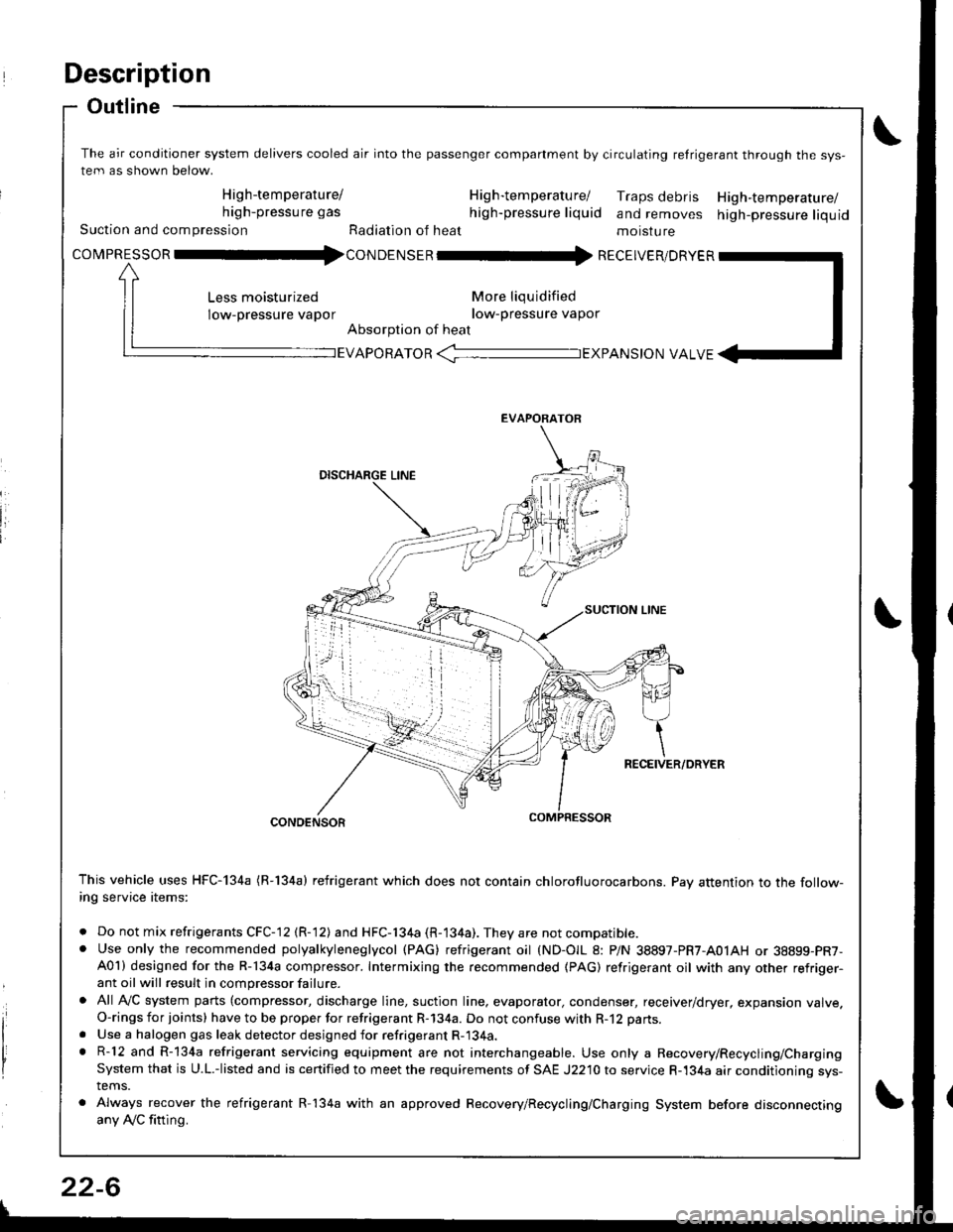
The air conditioner system delivers cooled air into the passenger companment by circulating retrigerant through the sys-
tem as shown below.
High-temperature/ H ig h-tem peratu rel Traps debris High-temperature/high-pressure gas high-pressure liquid and removes high-pressure liquidSuction and compression Radiation of heat moisture
covpnEsson -tl4con oetsen -rr{ REcEIvER/DRvER
More liqu idified
low-pressure vapor
Absorption of heat
Less moisturized
low-pressure vapor
EVAPORATOR -TEXPANS|ON VALVE
EVAPORATOR
CONDENSOR
This vehicle uses HFC-134a (R-134a) refrigerant which does not contain chlorofluorocarbons. Pay attention to the follow-ing service items:
. Do not mix refrigerants CFC-12 (R-12) and HFC-134a (R-134a). They are not compatible.. Use only the recommended polyalkyleneglycol (PAG) refrigerant oil (ND-OIL 8: P/N 38897-PR7-A01AH or 38899-PR7-A01) designed for the R-134a compressor. Intermixing the recommended (PAG) refrigerant oil with any other refriger-ant oil will result in compressor failure.
. All AVC system parts (compressor, discharge line, suction line. evaporator, condenser, receiver/dryer, expansion valve.O-rings for joints) have to be proper for refrigerant R-134a. Do not confuse with R-12 parts.
. Use a halogen gas leak detector designed for refrigerant R-134a.. R-12 and R-134a refrigerant servicing equipment are not interchangeable. Use only a Recovery/Recycling/ChargingSystem that is U.L.-listed and is certified to meet the requirements of SAE J2210 to service R-134a air conditioning sys-tems.
. Always recover the refrigerant R-134a with an approved Recovery/Recycling/Charging System before disconnectingany Ay'C fitting.
22-6
Page 1025 of 1681

J
Troubleshooting
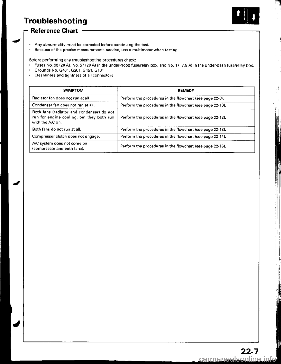
Reference Chart
. Any abnormality must be corrected before continuing the test.. Because of the precise measurements needed, use a multimeter when testing.
Before performing any troubleshooting procedures check:. Fuses No, 56 (20 A), No. 57 (20 A) in the under-hood fuse/relay box, and No. 17 {7.5 A) in rhe under-dash fuse/relay box.. Grounds No. G401, G201, G151, G101. Cleanliness and tightness of all connectors
I'IT
I
I
SYMPTOMREMEDY
Radiator fan does not run at all.Perform the procedures in the flowchart {see page 22-8).
Condenser fan does not run at all,Perform the procedures in the flowchart (see page 22-1O1.
Both fans {radiator and condenser) do not
run for engine cooling, but they both run
with the IVC on.
Perform the procedures in the tlowchart (see page 22-12).
Both fans do not run at all.Perform the procedures in the flowchart (see page 22-13).
Compressor clutch does not engage.Perform the procedures in the flowchart (see page 22-14).
l'lc system does not come on
{compressor and both fans).Perform the procedures in the flowchart (see page 22-15).
22-7
Page 1032 of 1681
Troubleshooting
- Compressor
Remove the compressor clutchrelay trom the unde.hood tuse/relay box, and test it {see page
22-19t.
Measure the voltage beNveen theNo.2 terminal (+) and bodyground (-).
ls there battery voltage?
Connect the No. 1 and No. 2 terminals with a jumper wire.
Discon nect the compressorclutch 1P conoector.
Check lor continuity in the REDwire betlveen the No. 1 terminaland the compressor clutch.
Reprir open in tha BED wirabotwoon th6 undar-hood fusc/rolay box and lhs comp.osrorclutch.
In3p6ct th€ compre3sor clulchclear'nc€ and the comDressorcfutch ti€fd coil (se€ ptge22-321.
\-
COMPRESSOR CLUICH RELAY 'P SOCKET
JUMPERWIRE
\
To page 22-15
22-14
\
Page 1033 of 1681
![HONDA INTEGRA 1998 4.G Workshop Manual COMPRESSOR CLUTCH RELAY P SOCIGT
I
,l
I
i:]
lll
i
ll
rl.
,i
lil
ECM CONNECTOR A (32PI
BLK/f,ED
WIRE SIDE OF FEMALE TERMINALS
ECM CONNECTOR C {31P}
BLU/RED
Connect the backprobe adapters to the stacki HONDA INTEGRA 1998 4.G Workshop Manual COMPRESSOR CLUTCH RELAY P SOCIGT
I
,l
I
i:]
lll
i
ll
rl.
,i
lil
ECM CONNECTOR A (32PI
BLK/f,ED
WIRE SIDE OF FEMALE TERMINALS
ECM CONNECTOR C {31P}
BLU/RED
Connect the backprobe adapters to the stacki](/manual-img/13/6069/w960_6069-1032.png)
COMPRESSOR CLUTCH RELAY 'P SOCIGT
I
,l
I
i:]
lll
i
ll
rl.
,i
lil
ECM CONNECTOR A (32PI
BLK/f,ED
WIRE SIDE OF FEMALE TERMINALS
ECM CONNECTOR C {31P}
BLU/RED
Connect the backprobe adapters to the stacking patch cords, and connect the cords to a mul-timeter. Using the wire insulation as a guide lor the contoured tip oI the backprobe adapter,gently slide the tip into the connector trom the wire side until it comes in contact with the ter-minalend ofthe wire {see section l1).
From page 22-14
*How to use the backprobe sets
Turn the ignition switch ON {11}.
i/leasure the voltage between theNo. 4 wire terminal (+) and bodyground {-).
Rcp.ir opon in tho BLK/YEL wirobetwsen tha undor.dash tu3a/rehy box rnd the undor.hoodfw6/i6lry box.
Turn tho ignition switch OFF, andreinstall the compressor clutch
Make suro the !y'C and heater fanswitches are OFF.
Turn the ignition switch ON {l1).
Using a *Backprobe Set (T/N
07SAZ - 001000A), measure th€voltage between the No. 17 termi-nal oI the ECM connocror A (32P)
and body ground wirh the ECMconnectors connected.
R.pair op.n in tho BLK/R€O wirobgtweon thg undor-hood fu!a/relly box 6nd th. ECM.
Using a *Backprobe Set (T/N
07SM - 001000A), moasure thevoltage betwe€n the No. 5 termi-nal of the ECM connector C (31P)
and body ground with the ECMconnectors connected.
Ropair op6n in tho BLU/RED wircbctwccn tho A/C diodc rnd theECM,
Subiiituto . known-good ECMrnd rochock. lt symptom/indicr-tion 90o3 away, .6placc the origi-n.l ECM.
WIRE SIOE OF FEMALE TERMINALS
22-15
Page 1035 of 1681
JView from wire sideFrom page 22-16
i,:,
il
rlt'
8LK/YEL l+)
YEL/WHT {+}
View from wire side
BLU/FED
(cont'd)
Turn the ignition switch ON {ll).
Measure the voltago between theBLK/YEL wire terminal (+) andbody ground (-).
Reprir opon in th€ BLK/YEL wir€batween the under-d.sh tuse/relay box rnd the A/C therm6tlt.
ls there battery vohageT
Moasure tho voltage between theYEL,A/VHT wire terminal (+) andbody ground (-).
Repair op6n in the YEL/WHTwire betwGen the A/C pressure
switch snd the A/C thermostat.ls th6re battery voltage?
Turn the ignition switch OFF.
Reconnect the A,/C thermostat 3Pconnector and connect the BLU/RED wire terminal to ground with
Do the radiator and con-denser fans run and thecompressor clutch engage?
Turn the ignition switch OFF anddisconnect the jumper wire.
To page 22'18
22-17