Page 1172 of 1681
)
t
J
Altelnator ttelr Inspecuon ano Aol
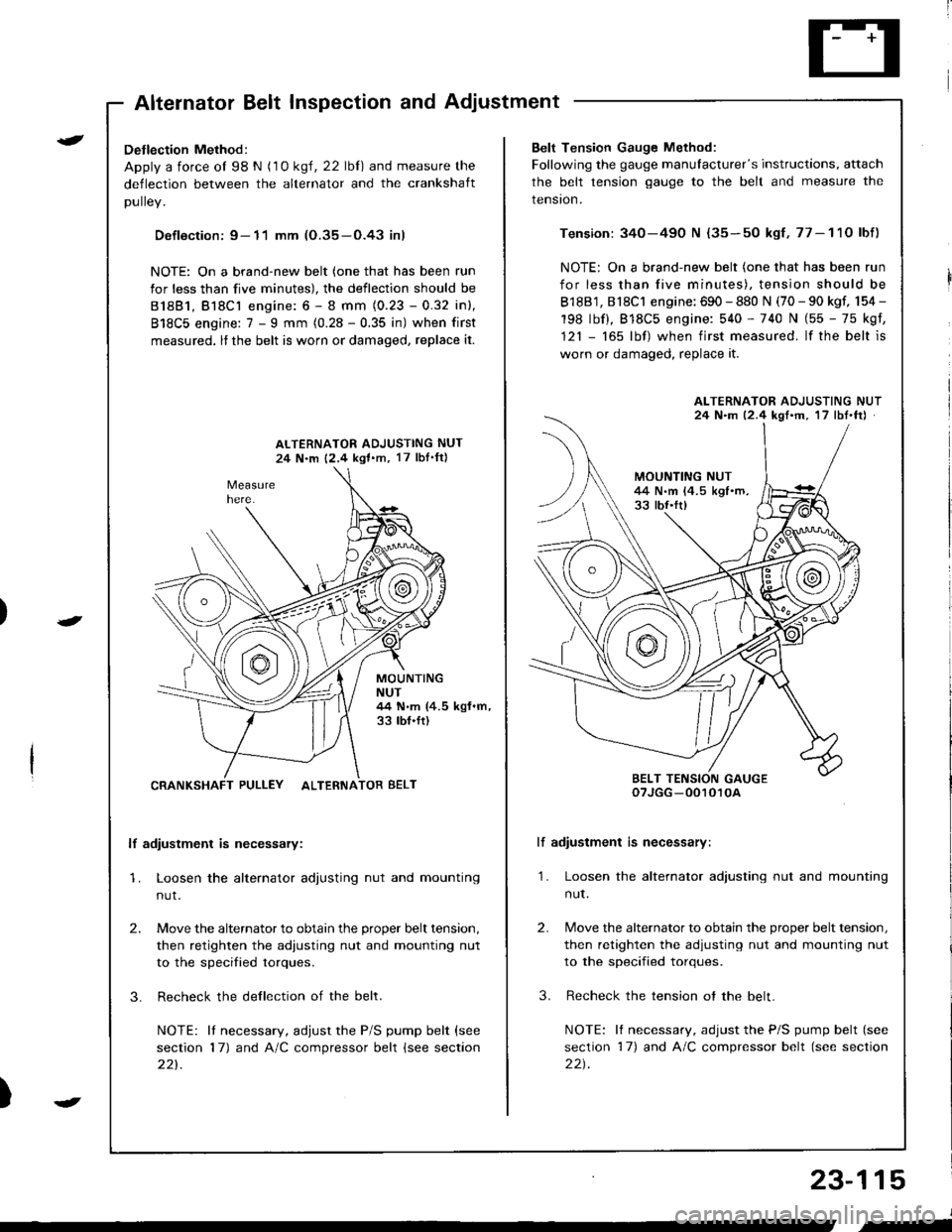
Detlection Method:
Apply a force ol 98 N (1 0 ksl, 22 lbl) and measure the
deflection between the alternator and the crankshaft
DUllev,
Defloction: 9- 11 mm (O.35-O.43 inl
NOTE: On a brand-new belt (one that has been run
for less than five minutes), the deflection should be
81881, Bl8Cl engine: 6 - 8 mm (0.23 - 0.32 inl,
818C5 engine: 7 - I mm (0.28 - 0.35 in) when first
measured, lf the belt is worn or damaged, replace it.
ALTERNATOR ADJUSTING NUT
24 N.m 12,4 kgl.m, 17 lbI'ftl
MOUNTINGNUT44 N.m (4.5 kgf.m,33 tbf.ft)
CRANKSHAFT PULLEY ALTERNATOR BELT
lf adiustment is necessary:
1. Loosen the alternator adjusting nut and mounting
nut.
2.
3.
Move the alternator to obtain the proper belt tension,
then retighten the adiusting nut and mounting nut
to the specified torques.
Recheck the dellection of the belt.
NOTE: lI necessary, adjust the P/S pump belt (see
section 17) and A/C compressor belt (see section
221.
Belt Tension Gauge Method:
Following the gauge manulacturer's instructions, attach
the belt tension gauge to the belt and measure the
tension.
Tension: 340-490 N {35-50 kgf,77-11O lbf)
NOTE: On a brand-new belt (one that has been run
for less than five minutes), tension should be
818B1, 818C1 engine: 690 - 880 N (70 - 90 kgf, 154 -
198 lbf), 818C5 engine: 540 - 740 N (55 - 75 kgf,
121 - 165 lbf) when first measured. lf the belt is
worn or damaged, replace it.
lf adiustment is necessary:
1. Loosen the alternator adjusting nut and mounting
nut.
2.
3.
Move the alternator to obtain the proper belt tension,
then retighten the adjusting nut and mounting nut
to the specified torques.
Recheck the tension ot the belt.
NOTE: It necessary, adjust the P/S pump belt (see
section 17) and A/C compressor belt (see section
22t.
ALTERNATOR ADJUSTING NUT24 N.m 12.4 kgf'm, 17 lbt.ftJ
BELT TENSION GAUGEoTJGG -0010r0A
23-115
J
,-
Page 1383 of 1681
).1
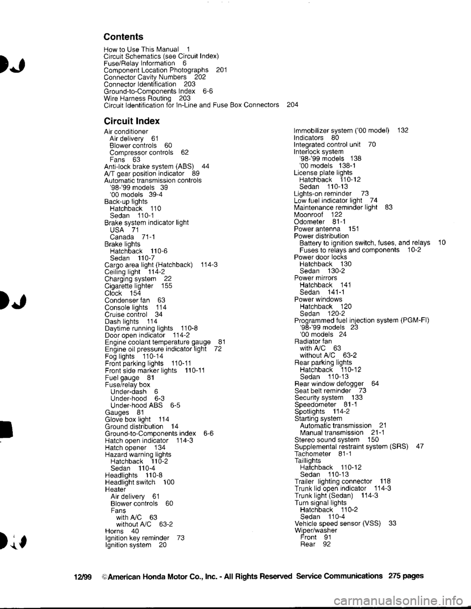
Contents
How to Use This l\.4anual 1Circuit Schematics (see Circuit Index)Fuse/Relaylnformation 6ComponentLocation Photographs 201
Connector Cavity Numbers 202Connectorldentification 203
Ground-to-Components Index 6-6Wire Harness Routing 203Circuit ldentification lor ln-Line and Fuse Box Connectors
Circuit Index
Air conditionerAir delivery 61Blower controls 60Compressor controls 62Fans 63Anti-lock brake system (ABS) 44A/T gear position indicator 89Automatic transmission controls'98199 models 39'00 models 39-4Back-up lightsHatchback 110Sedan 110- 1Brake system indicator light
USA 71Canada 71-1Brake lightsHatchback 110-6Sedan 110-7Cargo area light (Hatchback) 114-3Ceiling light 114-2Charging system 22Cigarette lighter 155
Clock 154Condenser fan 63Console lights 114Cruise control 34Dash lights 1 14Daytime running lights 110-8Door open indicator 114-2Engine coolant temperature gauge 81Engine oil pressure indicator light 72Fog lights 110-14Front parking lights 110-11Front side marker lights 110-11Fuel gauge 81Fuse/relay boxUnder-dash 6Under-hood 6-3Under-hood ABS 6-5Gauges 81Glove box light 114Ground distribution 14Ground-to-Componentsindex 6-6Hatch open indicator '114-3
Hatch opener '134
Hazard warning lightsHatchback 'l l0-2Sedan 110-4Headlights 1'10-8Headlight switch 100HeaterAir delivery 61Blower controls 60Fanswith A,/C 63without A,/C 63-2Horns 40lgnilion key reminder 73lgnition system 20
204
lmmobilizer system ('00 model) 132lndicators 80Integrated control unit 70Interlock system'98199 models 138'00 models 138-1License plate lightsHatchback 110-12Sedan 110-13Lights-on reminder 73Low fuel indicator light 74l\,4aintenance reminder light 83l\iloonroof 122Odometer 81-1Power antenna 151Power distributionBattery to ignilion switch, fuses, and relays
Fuses to relays and components 10-2Power door locksHatchback '130
Sedan 130-2Power mirrorsHatchback 141Sedan 141-1Power windowsHatchback 120Sedan 120-2Programmed fuel injection system (PGM-Fl)'98199 models 23'00 models 24Radiator fanwith tuC 63without A,/C 63-2Rear parking lightsHatchback 110-12Sedan 110- 13Rear window defogger 64Seat belt reminder 73Security system 133Speedometer Il-1Spotlights 114-2Starting syslemAutomalictransmission 21l\.4anualtransmission 21-1Stereo sound system 150Supplemental restraint system (SRS) 47Tachometer 81- 1TaillightsHatchback 110-12Sedan 110-13Trailer lighting conneclor 118Trunk lid open indicator 114-3Trunk light (Sedan) 114-3Turn signal lightsHatchback 110-2Sedan 110-4Vehicle speed sensor (VSS) 33Wiper/washerFront 91Rear 92
10
).1
I
Xr
12Fg oAmerican Honda Motor Co., Inc. - All Rights Reserved Service Communications 275 pages
Page 1390 of 1681
Circuit ldentification for In'Line and Fuse Box Connectors
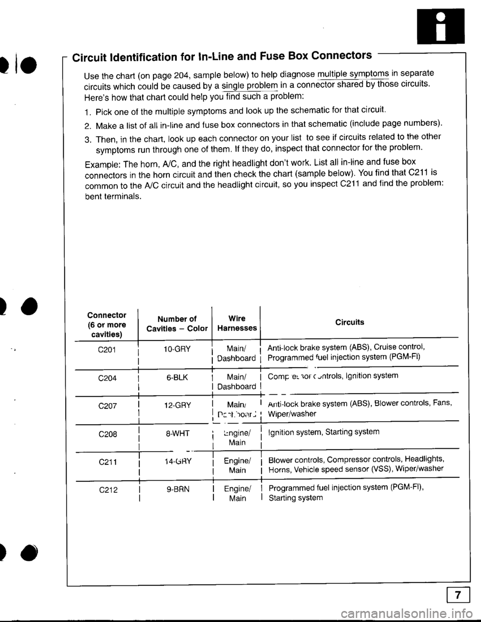
tuse the chart (on page 204, sample below) to help diagnose multiple symptoms in separate
circuits which could be caused by a single problem in a connect,oishared by those circuits'
Here's how that chart could help you find such a problem:
1. Pick one of the multiple symptoms and look up the schematic for that circuit'
2. Make a list of all in-lrne and fuse box connectors in that schematic (include page numbers).
3. Then, in the chart, look up each connector on your list to see if circuits related to the other
symptoms run through one of them. lf they do, inspect that connector for the problem.
Example: The horn, A,/C, and the right headlight don't work. List all in-line and fuse box
connectors in the horn circuit and then check the chart (sample below). You find that C211 is
common to the A,/C circuit and the headlight circuit, so you inspect c211 and find the problem:
bent terminals.
)Connector
(6 or more
cavities)
Numbel of
Cavities - Color
1O-GRY
I 12-GRY
I
Wire
Harnesses
I Main/ | ComP er 'ror c.ntrols,
I Dashboard I
Circuits
Ant!lock brake system (ABS), Cruise control,
Programmed {uel injection system (PGM-FD
!ngrnei
lvlain
lgnition system
Antilock brake system (ABS), BIower controls, Fans,
Wiper/washer
lgnition system, Starting system
Blower controls, Compressor controls, Headlights'
Horns, Vehicle speed sensor (VSS), Wiper/washer
Programmed fuel injection system (PGM-Fl)'
Starting system
Engine/ |Main I
)
Page 1401 of 1681
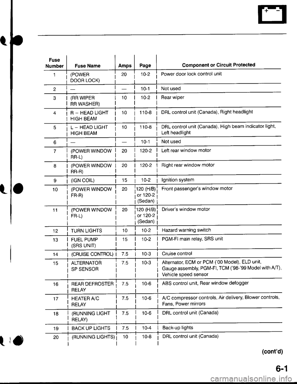
Fuse
NumberFuse NameAmpsPagecomponent or circuit Protected
(POWER
DOOR LOCK)
(RR WIPER
RR WASHER)
R _ HEAD LIGHT
HIGH BEAM
j 1o-2Power door lock control unit
10-2 | Rear wiper
I
tto-e i onLcontrol unit (Canada), Right headlight
L _ HEAD LIGHT
HIGH BEAM
(POWER WINDOW
RR-L)
i 1 10-8i DRL control unit (Canada), High beam indicator light,
i Left headlight
1 0-1Not used
| 1zo-z
I
I Left rear window motor
| (lGN colL)| 15
(POWER WINDOW
FR-R)
(POWEB WINDOW
FR-L)
I Right rear window molor
I
Front passenger's window motol
Driver's window motor
| 120-2
i120 (H/B)
iot 120-2
l(Sedan)
i120 (H/B)
l0:120 ?
IJ13
TURN LIGHTS
FUEL PUMP
(SRS UNIT)
(Sedan)
'lo-2Hazard warning switch
1O-2 | PGM-FI main relay, SRS unit
I
14I (cRUlsE coNTRoL) | 7.510-3 | Cruise control
ALTERNATOR
SP SENSOR
7.510-3Alternator, ECM or PCM ('00 Model), ELD unit,
Gauge assembly, PGM-Fl, TCM ('98-'99 Modelwith A/f),
Vehicle speed sensor
i REAR DEFBOSTER ii RELAY i
10-6i ABS control unit, Rear window defogger
I HEATER A/C
: RELAY
fuC compressor controls, Air delivery, Blower controls,
Fans. Power mirrors
I tnururutruc ucxr I z.s
I otrt av I
I DRL control unit (Canada)10-6
I BACK UP LIGHTS | 7.s | 10-4 I Back-up lights
t
(RUNNTNG LTGHTS) ii DRL control unit (Canada)
(cont'd)
19
6-1
Page 1403 of 1681
- Under-hood Fuse/Relay Box
Front View
T102Oo engine wire harness)
*: Not Used
Rear View
c2l5To main wire harness
T1[ro battery)
c905[ro F/Ccompressor)clutch relay)
c2t8[fo main wire harness)Oo main
(cont'd)
D3
tr
tr
[J
r'1
IJ
r-t
IJ
r'151
LI
r-156
IJ
r"l57
LI
Llowire harness)
6-3
Page 1404 of 1681
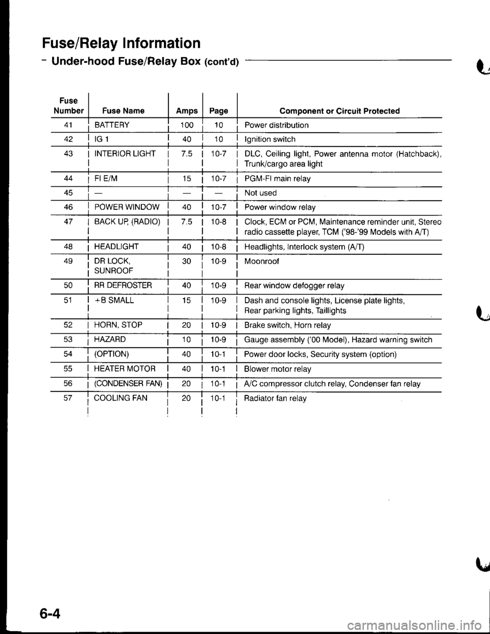
Fuse/Relay I nformation
- Under-hood Fuse/Relay Box (cont'd)
Fuse
NumberFuse NameAmpsPage
BATTERY
I INTERIOR LIGHT
I
1 7.5 110-7 I
I
Component or Circuil Protected
Power distribution
lgnition switch
DLC, Ceiling light, Power antenna motor (Hatchback),
Trunk/cargo area light
47
I Fl E/lvl
POWER WINDOW
I BACK UP (RADTO)
I
15 | 1 0-7 I PGM-FI main relay
Not used
Power window relay
Clock, ECM or PCM, Maintenance reminder unit, Stereo
radio cassette player, TCM ('98-'99 Models with A'/T)
7.5 |10-8
I HEADLIGHT| 40 | 10-8 | Headlights, Interlock system (A/T)
49i DR LOCK,
i suNRooF
10-9 i Moonroof
I
I RR DEFROSTER
+ B SMALL
I Rear window detogger relay
I Dash and console lights, License plate lights,
I Rear parking lights, Taillights
I HORN, STOP
i HAZARD
10-9 | Brake switch, Horn relay
i Gauge assembly ('00 Model), Hazard warning switch
40 | to t I Power door locks, Security system (option)
I HEATER MOTOR II t 0-1I Blower motor relay
20 I 10-1 ; A,/C compressor clutch relay, Condenser fan relay
i Radiator fan relay1 0-1
6-4
Page 1414 of 1681
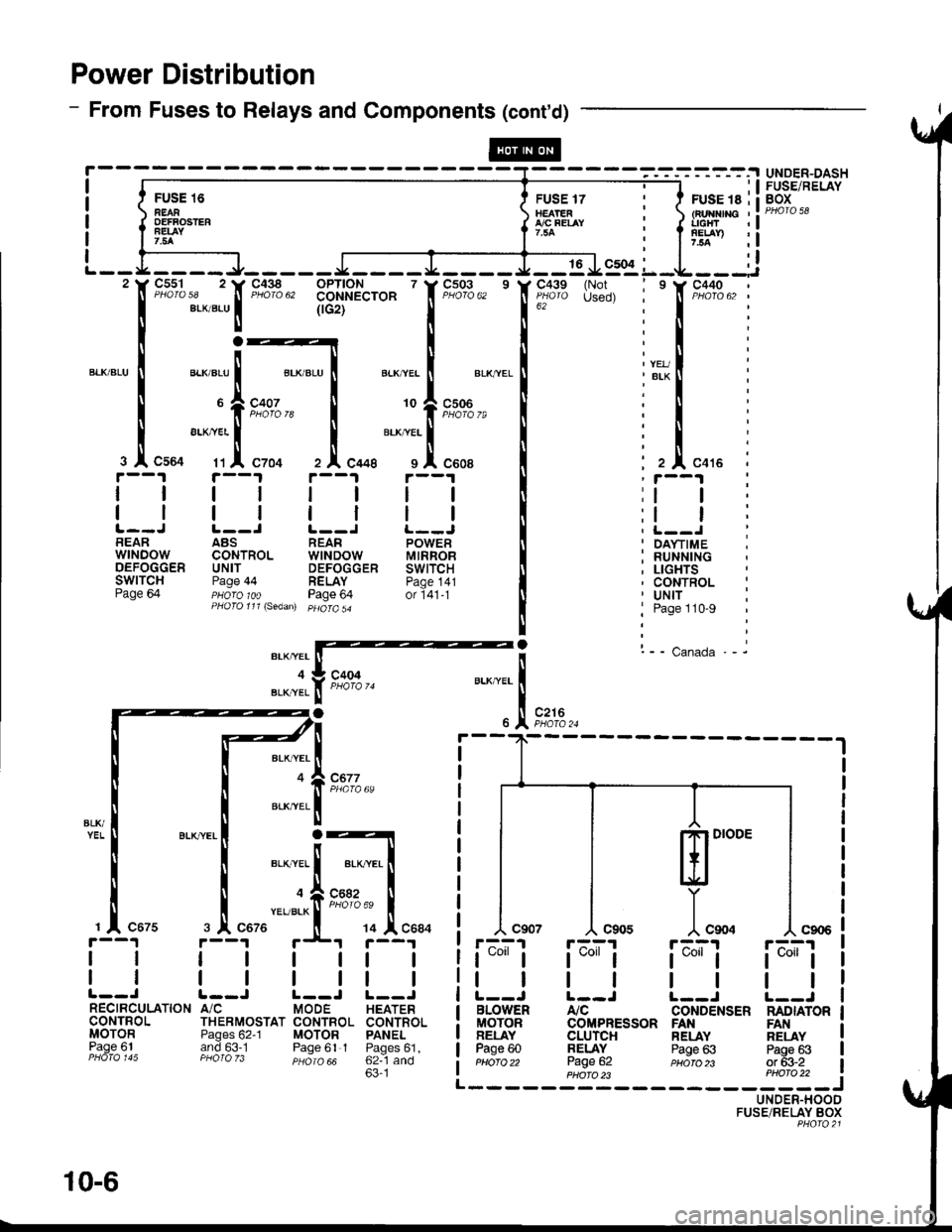
Power Distribution
- From Fuses to Relays and Components (cont'd)
FU'E 16 Err*rrilnEAR tEArEn : tFurflnc ,:oEFFosrER { flfo"t-t i { l'rtTr :!7.5A I : I 7.5a ,l
ffi-.^,; l:lL - - L __ _ _ J_ _ _ _ _ J __ _ _ I _ __ _ J _ _ 16 J9:91 L _L _ _ _:i'tr F"?%,, 'tr'F"Xlg", 331'$A"'o* ' f F;03,, ' lf ;'"11'" {H!, i ' f t"X13,, :
I eLxaLul (rcrt'--'-' I 16z
""""'
i I :
r:_lrl:
":1",-:ri;:t
ll".",:{.tFz'€; I lll".,. i
rt i'--t rt i--t i ;i--i i
t__J t__l r__J !._-J ! i t__.t iBEAR ABS REAR POWER II ' DA\.TIME ;wrNDow coNTRoL wtNDow MtRRoB I : RUNNTNGoEFoccER uNrr DEFoccER swtrcH It ; LtcHTsSWITCH Page 44 RELAY paoe 141 I , CONTROL :Page 64 pHoro 1oo Page 64 or i41-t [ ' Uttf :PHoro111\sedan) pHoro5a
! j Page 110-9
|
! l-- canada.- it*rarffi'
"JI.f t*', u..^""1
-.
)t .,1, r*,.
BLK,YEL
BLK,YEL
ml'"
]"*.r-A?1
t*"1
tl
BLOWENMOTORBELAYPage 60Pttofo 22
rF^;'l
t*l
tl
Atc
UNDER-DASHFUSE/RELAYBOX
c677
L--J |.--J L--JA/C MODE HEATERTHERMOSTAT CONTBOL CONTROI.Pages 62-1 MOTOR PANELand 63.1 Paqe 61 I Paoes61.PHO|O zJ psiro aa 62--1 and63'1
r'--?1 r;^;'r
t*"lt*"1
tttlL--J L--JCONDENSER NADIATORCOMPRESSOR FANCLUrcHBELAYPage 62
RELAYPage 63
FANRELAYPags 63or 63-2PHA|O )3 PHO|O 22 i------JUNDER-HOODFUSE/RELAY BOXPHQ|O2l
@
10-6
Page 1450 of 1681
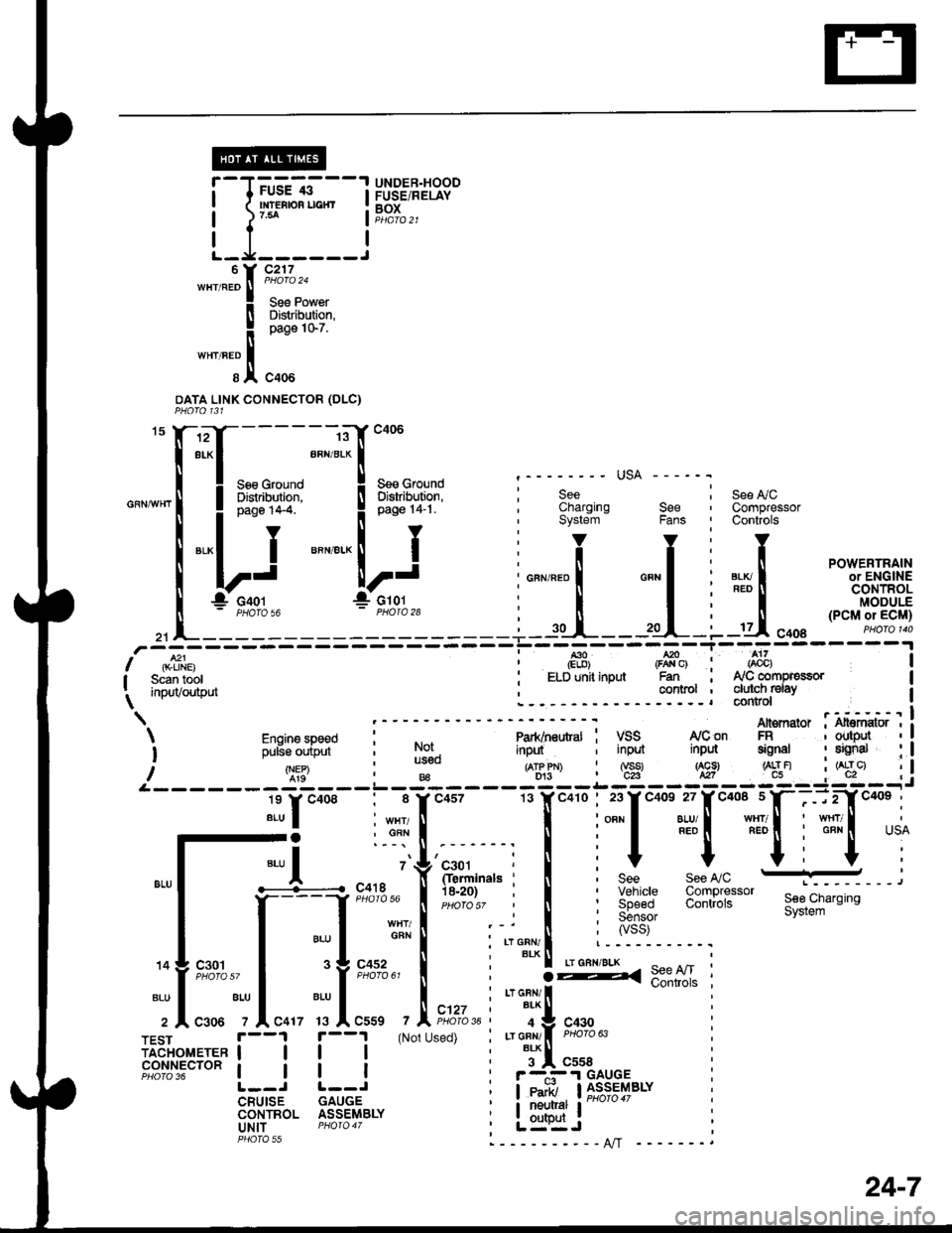
UNDER.HOODFUSE/RELAYBOXl'-J-'uC-*---l
Lfl:::j
*".^;[
k;i*,,
! oao" to'z
*"''"T.1,
"oou
DATA LINK CONNECTOR (DLC}
See L/CCompressorControls
"X-*T-__-;"E::"
Il.Ll--- ;"--.'-[*"
| ! :ne,t*c il ;*,f,n*.1 i ;;"
-' usA ---
"-""'l
"*i,:Y' """"..ij1"
i"""".tlf*' "".7
u,i"""'*.16J
,]:f J
Jcror
I Scan tool : ELD unit inputI i.^'tr/^,fh,'t . CollllolI ,r,PuvvurrruL\L- - -r*i**"i
I *. ry'con An€mator : i.ff*o'I iinput ; input inpd signal : sEnal : I
- - i'ril - :- g - - iE- - i:i - - l:i - -,, i
, I i;:l*'#[""*ifitf{*,u
rals . n bee rccwu E---,
. i I :X3:'""1" 3:lllJij*'see,ciarsins; I :55;;, system
n ; ryss)
i'Tlli '----------r
; :g< 9:"lI '
i r"r cnr, | *"""- :, BLK T: 4 Y 943! |: Lr GFN/ I PHoro 63
i i*l "uu,:-.i.I GAUGE; leairi, llJ_s*l4BLY
i it:l*i' r-"'"" :, L=":Jl----------AlT -
'
Engine speed l"-----'--"
i ;,rs;,ipi,i- i l$.
/q:9'B€L------------l-
lr.r"oo. : 8 rc4s7
Jl :"-r!
".,1 .-L-.... ".
''{'r*,"',
il*'H;{l !-,
TFsr |. --1 f --1 (Not Used) ;iadiror,reren | | | | |
F8ilil5"'o"t | | | :
L--J L--JCRUISE GAUGECONTROL ASSEMBLYuNlT PHOfO 47PHOTA rr
c457
24-7
36