Page 1302 of 1681
Passenger's Door Lock Actuator Test
1. Remove the door panel (see section 20).
2. Disconnect the 2P connector from the actuator.
Front Passenger's Door:
lerminal side
ACTUATOR
)J
23-247
Rear Passenger's Door:
NOTE: Left rear actuator is shown, right rear actuator
is similar.
View from lerminal side
Check actuator operation by connecting power and
ground according to the table.
CAUTION: To prevent damage to the actuator, ap-
ply battery voltage only momenta.ily.
;
4. lf the actuator tails to work properly, replace it.
Term inal
Position
B
LOCKo@
UNLOCKoo
Page 1303 of 1681
Power Door Locks
Driver's Door Key Cylinder
Switch Test
1. Remove the door panel (see section 20).
2. Disconnect the 2P connector f.om the switch.
terminal side
Check tor continuity between the terminals in eachswitch position according to the table.
Front Passenger's Door Key Cylinder
Switch Test
1. Remove the door panel (see section 20).
2. Disconnect the 3P connector from the switch.
FRONTPASSENGER'SDOOR KEYCYLINDERSwlTCH
CONNECTOR
3. Check for continuity between the terminals in eachswitch position according to the table.
Terminal
il;------__\tt
UNLOCKoo
OFF
Terminal
P**--__\c
LOCKo--o
UNLOCKoo
UNTOCK<
I
UNLOCK
r--O\:
I LOCK
23-248
(--l__!J KEYtil
Page 1304 of 1681
Door Lock Switch Test
1. Remove the inner handle trim.
2. Disconnect the 3P connector from the switch.
3. Check tor continuity between the terminals in each
switch position according to the table.
)
oooRLOCKswtTcH
Terminal
t"r--
-\Bc
LOCKo-----o
OFF
UNLOCKoo
4
23-249
Page 1305 of 1681
Power Door Locks
Hatch Lock Actuator Test
Remove the rear t.im panel (see section 20).
Disconnect the 6P connector from the actuator.
1.1.
2.
Hatch Key Cylinder Switch Test
Remove the rear trim panel (see section 20).
Disconnect the 3P connector from the switch.
3. Check for continuitv between the terminals in each
switch position according to the table.
6P CONNECTOR
3. Check actuator operation by connecting power andground according to the table.
CAUTION: To prev€nt damage to the actuator,
apply battery voltage only momeniarily.
1 lf the actuator fails to work properly, replace it,
23-250
Terminal
ilil;---tBc
LOCKoo
UNLOCKo
Terminal
ilil;-]E
LOCK@o
UNLOCKoo
UNLOCK
.-,4
I LOCK
| !J KEY
Page 1306 of 1681
Hatch Opener
Circuit DiagramHatch Latch Switch Test
Remove the rear trim panel lsee section 20).
Disconnect the 6P connector from the switch.
3. Check for continuity between the terminals in each
switch position according to the table.
HATCHOPENEHRELAY
HATCHOPENERACTUATOB
UNDER-HOODFUSE/RELAYBOX
UNDER.DASHFUSE/RELAYBOX
la :llf q ^ll
ELUMHT YEURED
tl
[S-l*0,., f/tl| IoPENEF lt.l I
I ? l'*n'" +_i
tl8LK BLK
tl
tl
tt.:
G503 G503
BATTEFY
(+)
Y
I
-r--t
I I lm,1
uI| )Nov II f. (4oA) |rT '
IWHT/RED
I-r----| )ur II L (2oA) I
IWHTiGRN
fi--l->t_:___J-KEY
Terminal
:- ..- crosrUon-1UNLOCK
LOCK
F
23-251
-----t1< IKEY--,_)
J
Page 1313 of 1681

Cruise Control
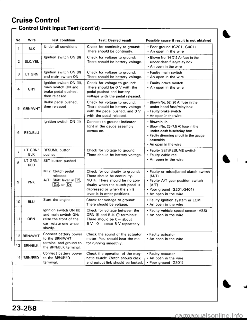
- Control Unit InputTest(cont'dl
IBLKUnder all conditionsCheck for continuity to ground:
There should be continuity.
. Poor ground (G20l, G401). An open in the wire
2BLK/YEL
lgnition switch ON {ll}Check for voltage to ground:
There should be battery voltage.
. Blown No. l4 (7.5 Alfuse in the
under-dash fuse/relay box. An open in the wire
3LT GRNlgnition switch ON (ll)
and main switch ON
Check for voltage to ground:
There should be battery voltage.
. Faulty main swjtch. An open in the wire
GRY
lgnition switch ON (ll),
main switch ON and
brake pedal pushed,
then released
Check for voltage to ground:
There should be O V with the
pedal pushed and battery
voltage with the pedal released.
. Faulty brake switch. An open in the wire
5GRN/WHT
Brake pedal pushed,
then released
Check for voltage to ground:
There should be battery voltage
with the pedal pushed, and 0 V
with the pedal released.
Blown No. 52 (20 A)fuse in the
under-hood fuse/relay box
Faulty brake switch
An open in the wire
6RED/BLU
lgnition switch ON (ll)Connect to ground: lndicator
light in the gauge assembly
comes on.
Blown bulb
Blown No. 25 (7.5 A)fuse in the
under-dash fuse/relay box
Faulty dimming circuit in the gauge
assembly
An open in the wire
7LT GRN/
BLK
RESUME button
pushed
Check tor voltage to ground:
There should be battery voltage.
Faulty SET/RESUME switch
Faulty cable reel
An open in the wire8LT GRN/
RED
SET button pushed
IPNK
MT/: Clutch pedal
released
A/Tr Shift lever in [2l,
[Dl]. o, [o'l
-
Check for continuity to ground:
There should be continuity.
NOTE: There should be no con-
tinuity when the clutch pedal is
depressed or when the shift
lever is in other positions.
Faulty or misadjusted clutch switch(M/T)
Faulty A/T gear position switch(A/T)
Poor ground (G201,G401)
An open in the wire
't0BLUStart the engine.Check lor voltage to ground:
There should be voltage.
. Faulty ignition system or ECM. An open in the wire
't1ORN
lgnition switch ON (ll)
and main switch ON;
raase the front of the
car, rotate one wheel
slowly.
Check for voltage between the
ORN @ and BLK O terminals:
There should be 0- about
5 V-O- about 5 V repeatedly.
. Faulty vehicle speed sensor {VSS). An open in the wire
BRN/WHTConnect battery power
to the BRN/WHT
terminal and ground to
the BRN/BLK terminal.
Check the sound of the actuator
motor: You should hear the mo-
tor running smoothly.
. Faulty actuator. An open in the wire
BRNi BLK
Connect battery power
to the BRN/RED
Iermrnal.
Check the operation of the mag-
netic clutch: Clutch should click
and output link should be locked.
Faulty actuator
An open in the wire
Poor ground (G30'l)
No. Wire Test conditionTest: Desiled result Possible cause il lesult is not obtained
' 4 I BRN/RED
{
{
23-258
-L
Page 1319 of 1681

Cruise Gontrol
1.
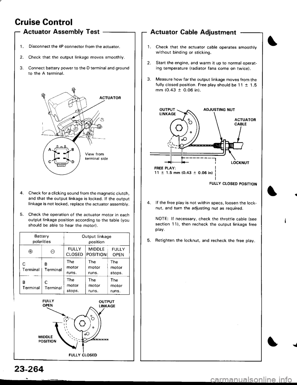
Actuatol Assembly Test
Disconnect the 4P connector from the actuator.
Check that the output linkage moves smoothly.
Connect battery power to the D terminal and ground
to the A terminal.
ACTUATOR
Check tor a clicking sound from the magnetic clutch.
and that the output linkage is locked. lf the outputlinkage is not locked, replace the actuator assembly.
Check the operation of the actuator moror In eacn
output linkage position according to the table (you
should be able to hear the motor).
FULLY CLOS€D
2.
3.
3.
23-264
Actuator Cable Adjustment
Check that the actuator cable operates smoothly
without binding or sticking.
Start the engine, and warm it up to normal operat-
ing temperature (radiator fans come on twice).
Measure how far the output linkage moves from thefully closed position. Free play should be 11 t 1,5mm (0.43 t 0.06 in).
FREE PLAY:1M.5 mm (0.43 1 0.06 in)
FULLY CLOSED POSITTON
4. lf the free play is not within specs, loosen the lock-
nut, and turn the adjusting nut as required.
NOTE: It necessary, check the throttle cable (see
section 1 1), then recheck the output linkage lreeplay.
5. Retighten the locknut, and recheck the free play.
^ffi"
c17i l,io
Battery
polaritiesOutput linkage
position
ooFULLY
CLOSED
MIDDLE
POSITION
FULLY
OPEN
c
Terminal
B
Terminal
The
moror
runs.
The
molor
runs.
The
motor
stops.
B
Terminal
c
Terminal
The
motor
stops.
The
motor
runs.
The
motor
runs.
{
Page 1329 of 1681

1.
2.
Replacement
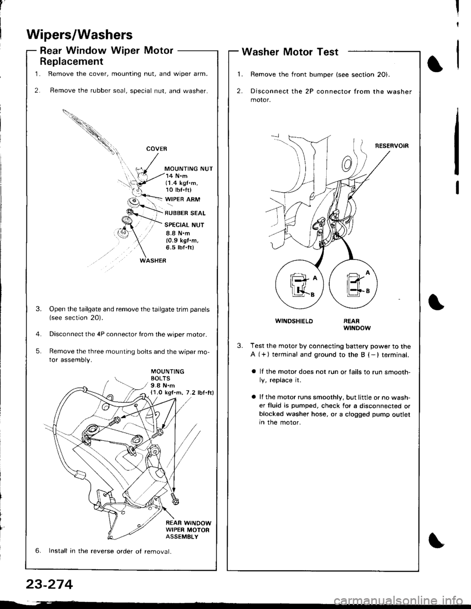
Remove the cover, mounting nut, and wiper arm.
Remove the rubber seal, special nut, and washer.
COVEB
MOUNTING NUT
WASHER
14 N'm(1.4 kgt.m,10 tbf.tr)
WIPER ARM
RUBBER SEAL
SPECIAL NUT
8.8 N.m
10.9 kgf.m.6.5 tbf'fr)
MOUNTINGBOLTS9.8 N.m11.0 kgl.m, 7.2 lbl.lrl
REAR WINOOWWIPER MOTORASSEMELY
3.Open the tailgate and remove the tailgate trim panels
{see section 20).
Disconnect the 4P connector trom the wiper motor.
Remove the three mounting bolts and the wiper mo-
tor assembly.
5.
6. Install in the reverse order ot removal.
,'II
t
Wipers/Washers
Rear Window Wiper MotorWasher Motor Test
l�
2.
Remove the front bumper (see section 20).
Disconnect the 2P connector from the washer
motor.
RESERVOIR
1
WINDSHIELDREARwtNDow
3.Test the motor by connecting battery power to the
A (+) terminal and ground to the B (-lterminal.
a lf the motor does not run or fails to run smooth-
ly, replace it.
a lf the motor runs smoothly, but little or no wash-
er fluid is pumped, check for a disconnected orblocked washer hose, or a clogged pump outletIn the motor.
23-274