1998 HONDA INTEGRA lock
[x] Cancel search: lockPage 1390 of 1681
Circuit ldentification for In'Line and Fuse Box Connectors
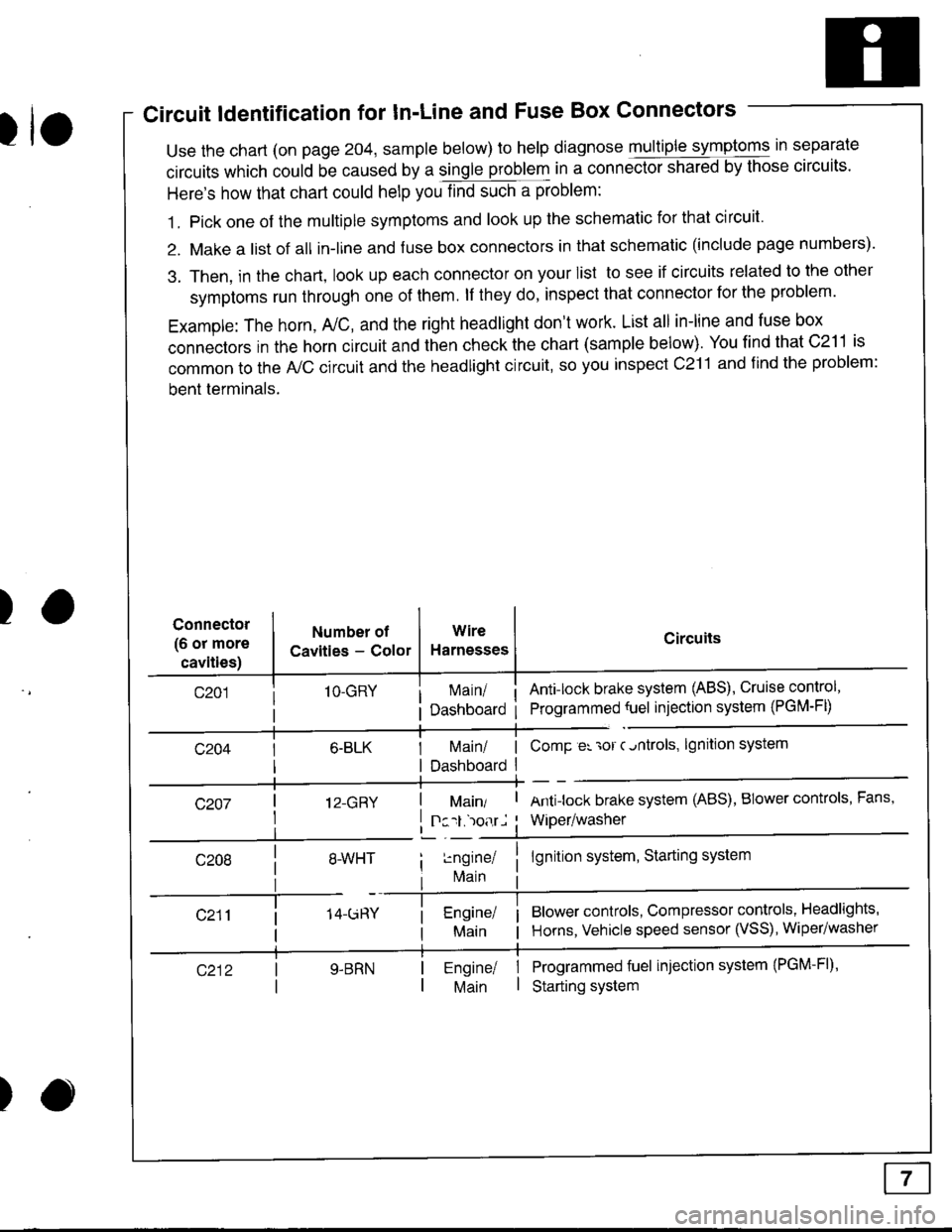
tuse the chart (on page 204, sample below) to help diagnose multiple symptoms in separate
circuits which could be caused by a single problem in a connect,oishared by those circuits'
Here's how that chart could help you find such a problem:
1. Pick one of the multiple symptoms and look up the schematic for that circuit'
2. Make a list of all in-lrne and fuse box connectors in that schematic (include page numbers).
3. Then, in the chart, look up each connector on your list to see if circuits related to the other
symptoms run through one of them. lf they do, inspect that connector for the problem.
Example: The horn, A,/C, and the right headlight don't work. List all in-line and fuse box
connectors in the horn circuit and then check the chart (sample below). You find that C211 is
common to the A,/C circuit and the headlight circuit, so you inspect c211 and find the problem:
bent terminals.
)Connector
(6 or more
cavities)
Numbel of
Cavities - Color
1O-GRY
I 12-GRY
I
Wire
Harnesses
I Main/ | ComP er 'ror c.ntrols,
I Dashboard I
Circuits
Ant!lock brake system (ABS), Cruise control,
Programmed {uel injection system (PGM-FD
!ngrnei
lvlain
lgnition system
Antilock brake system (ABS), BIower controls, Fans,
Wiper/washer
lgnition system, Starting system
Blower controls, Compressor controls, Headlights'
Horns, Vehicle speed sensor (VSS), Wiper/washer
Programmed fuel injection system (PGM-Fl)'
Starting system
Engine/ |Main I
)
Page 1393 of 1681
How To Use This Manual
Symbols
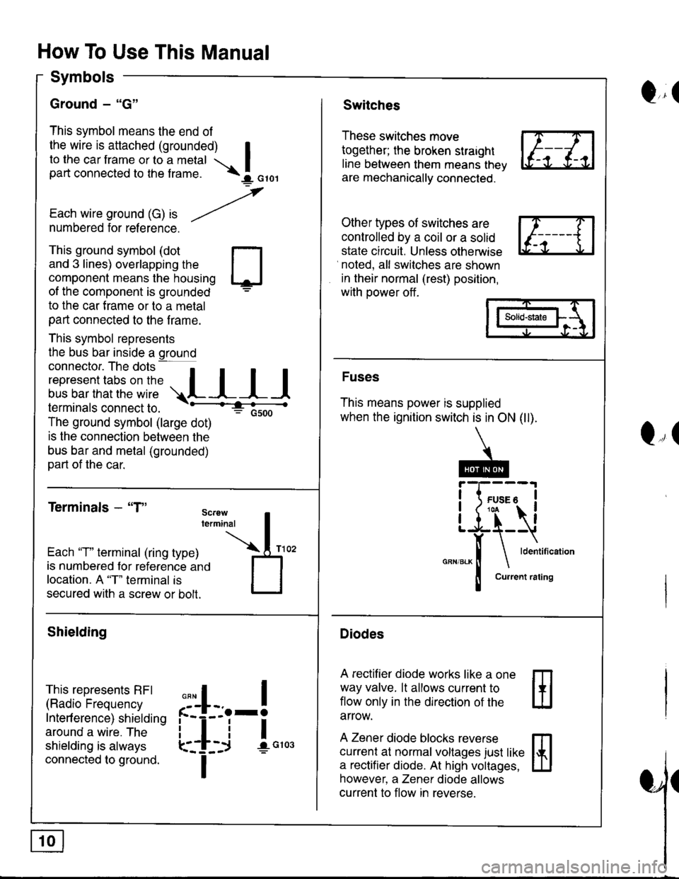
Ground - "G"
This symbol means the end of
the wire is attached (grounded) Ito the car frame or to a metal Ipart connected to the f rame. \I orol
,
Each wire ground (G) ," -/numbered for reference.
Q,(Switches
These switches move
together; the broken straight
line between them means thev
are mechanically connected.
Other types of switches are
controlled by a coil or a solid
state circuit. Unless otherwise
noted, all switches are shown
in their normal (rest) position,
with power off .
This ground symbol (dot
and 3 lines) overlapping the
component means the housing
of the component is grounded
to the car f rame or to a metal
part connected to the f rame.
This symbol represents
the bus bar inside a ground
connector. The dots a
i"r*"""*nn"l,':" .,.L I I I
lermtnals connectto. -'--'-:t"'--------<
The ground symbol (large dot)
: Gsoo
is the connection between the
bus bar and metal (grounded)
part of the car.
Terminals - "T"
m
ffi
Solid-state
Fuses
This means power is supplied
when the ignition switch is in ON (ll).
Diodes
A rectifier diode works like a one
way valve. lt allows current to
flow only in the dlrection of the
arrow.
A Zener diode blocks reverse
currenl at normal voltages just like
a rectifier diode. At high voltages,
however, a Zener diode allows
current to flow in reverse.
Q,(
Each 'T" terminal (ring type)
is numbered for reference ano
location. A "T" terminal is
secured with a screw or bolt.
Shielding
This represents RFI
(Radio Frequency
Interf erence) shielding
around a wire. The
shielding is always
connected to ground.
,,,
n
:'iL.-!
L-_+i !",*
I
Page 1401 of 1681
Fuse
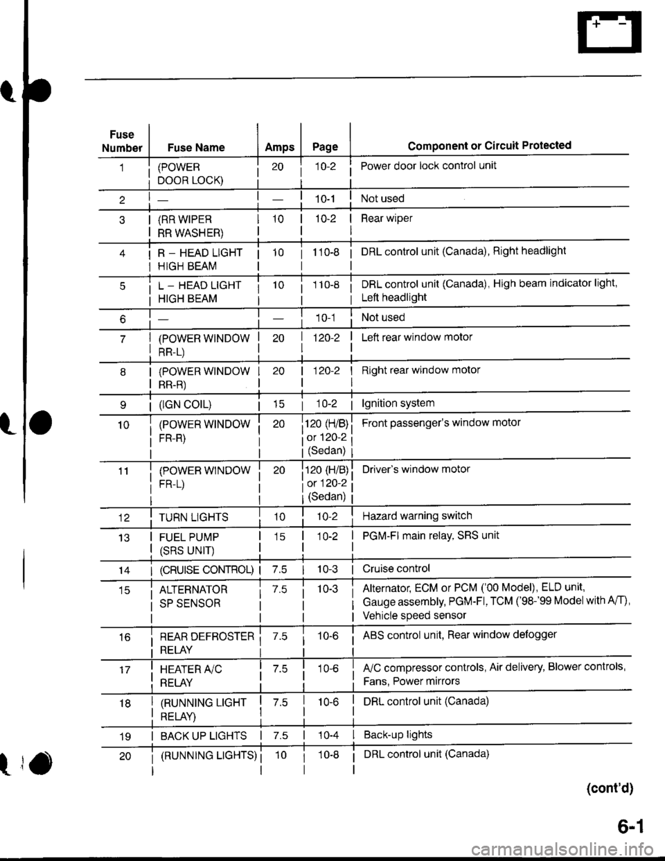
NumberFuse NameAmpsPagecomponent or circuit Protected
(POWER
DOOR LOCK)
(RR WIPER
RR WASHER)
R _ HEAD LIGHT
HIGH BEAM
j 1o-2Power door lock control unit
10-2 | Rear wiper
I
tto-e i onLcontrol unit (Canada), Right headlight
L _ HEAD LIGHT
HIGH BEAM
(POWER WINDOW
RR-L)
i 1 10-8i DRL control unit (Canada), High beam indicator light,
i Left headlight
1 0-1Not used
| 1zo-z
I
I Left rear window motor
| (lGN colL)| 15
(POWER WINDOW
FR-R)
(POWEB WINDOW
FR-L)
I Right rear window molor
I
Front passenger's window motol
Driver's window motor
| 120-2
i120 (H/B)
iot 120-2
l(Sedan)
i120 (H/B)
l0:120 ?
IJ13
TURN LIGHTS
FUEL PUMP
(SRS UNIT)
(Sedan)
'lo-2Hazard warning switch
1O-2 | PGM-FI main relay, SRS unit
I
14I (cRUlsE coNTRoL) | 7.510-3 | Cruise control
ALTERNATOR
SP SENSOR
7.510-3Alternator, ECM or PCM ('00 Model), ELD unit,
Gauge assembly, PGM-Fl, TCM ('98-'99 Modelwith A/f),
Vehicle speed sensor
i REAR DEFBOSTER ii RELAY i
10-6i ABS control unit, Rear window defogger
I HEATER A/C
: RELAY
fuC compressor controls, Air delivery, Blower controls,
Fans. Power mirrors
I tnururutruc ucxr I z.s
I otrt av I
I DRL control unit (Canada)10-6
I BACK UP LIGHTS | 7.s | 10-4 I Back-up lights
t
(RUNNTNG LTGHTS) ii DRL control unit (Canada)
(cont'd)
19
6-1
Page 1402 of 1681
FuserRelay I nformation
- Under-dash Fuse/Relay Box (cont'd)
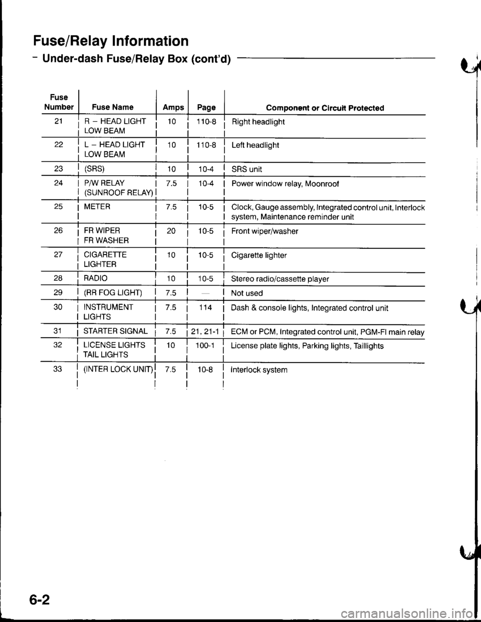
Fuse
Number
i R - HEAD LTGHT ii LOWBEAM i
Fuse NameAmpsPageComponent or Clrcull Protected
10 ii Right headlight
! L _ HEAD LIGHT I
I row eenu I
10 i110-8Left headlight
(sRs)I roSRS unit
24 I P/IV RELAY IPower window relav. Moonroof
l(suNRooFBELA!l
7.5 I 10-4 |
tl
25 | METER | 7.5 | 10-5 |
rttl
Clock, Gauge assembly, Integrated control unit, Interlock
system, Maintenance reminder unit
Front wiper/washer26 i FR W|PER
I FR WASHEB
27 | crcnnerre
i LTGHTER
28 i RApro i10 i
Cigarette lighter
10-s iStereo radio/cassette player
30 I INSTRUMENT
I LIGHTS
2e | (RR Foc LtcHT) | z.s !
| 7.5 |
tl
3'1 i STARTER STGNAL21,21-1 1
32 i LTCENSE LtcHrS Ii TAIL LIGHTS ii 1001 i
| (rNrER LocK uNrr)l
II
114 | Dash & console lights, Integrated control unit
ECM or PCM, Integrated control unit, PGM-FI main relay
License plate lights, Parking lights, Taillights
Interlock system
6-2
Page 1404 of 1681
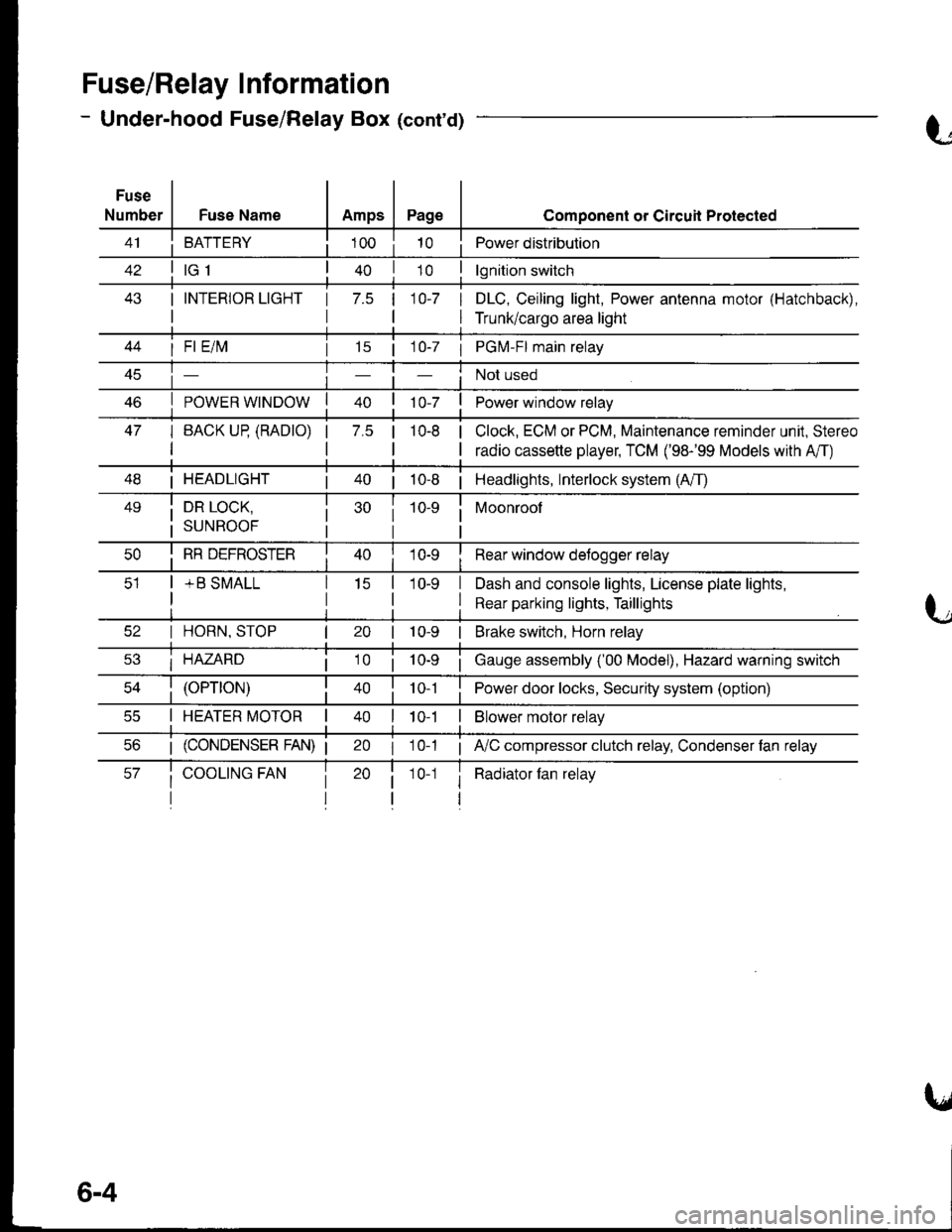
Fuse/Relay I nformation
- Under-hood Fuse/Relay Box (cont'd)
Fuse
NumberFuse NameAmpsPage
BATTERY
I INTERIOR LIGHT
I
1 7.5 110-7 I
I
Component or Circuil Protected
Power distribution
lgnition switch
DLC, Ceiling light, Power antenna motor (Hatchback),
Trunk/cargo area light
47
I Fl E/lvl
POWER WINDOW
I BACK UP (RADTO)
I
15 | 1 0-7 I PGM-FI main relay
Not used
Power window relay
Clock, ECM or PCM, Maintenance reminder unit, Stereo
radio cassette player, TCM ('98-'99 Models with A'/T)
7.5 |10-8
I HEADLIGHT| 40 | 10-8 | Headlights, Interlock system (A/T)
49i DR LOCK,
i suNRooF
10-9 i Moonroof
I
I RR DEFROSTER
+ B SMALL
I Rear window detogger relay
I Dash and console lights, License plate lights,
I Rear parking lights, Taillights
I HORN, STOP
i HAZARD
10-9 | Brake switch, Horn relay
i Gauge assembly ('00 Model), Hazard warning switch
40 | to t I Power door locks, Security system (option)
I HEATER MOTOR II t 0-1I Blower motor relay
20 I 10-1 ; A,/C compressor clutch relay, Condenser fan relay
i Radiator fan relay1 0-1
6-4
Page 1406 of 1681
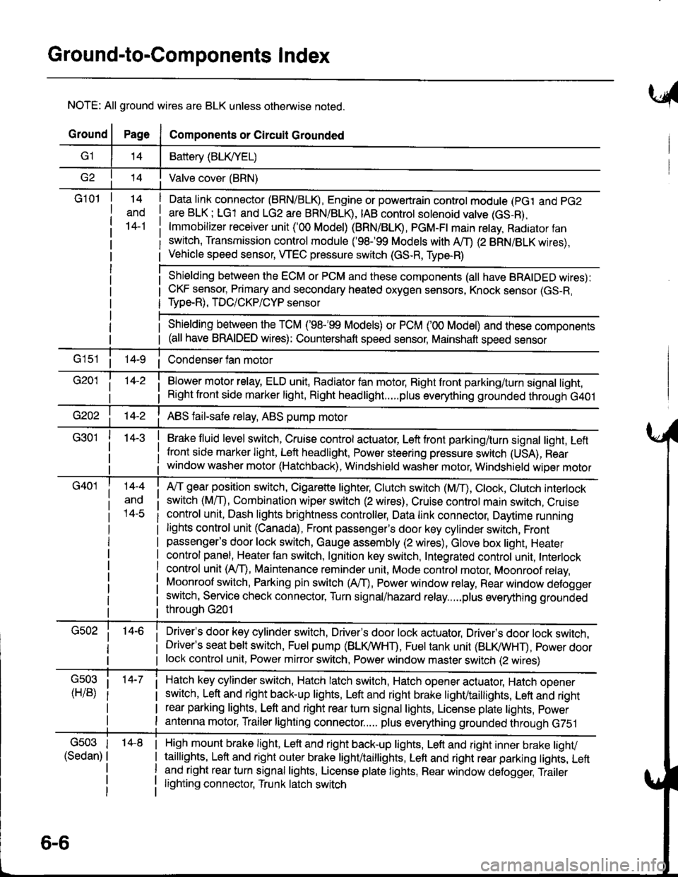
Ground-to-Components I ndex
NOTE: All ground wires are BLK unless otherwise noted.
GroundPageComponents or Circuit Grounded
Battery (BLIVYEL)
--t'I Valve cover (BRN)
G101t.+
and
14-1
Daia link connector (BRN/BLK), Engine or powertrain controt module (pct and pG2
are BLK; LG1 and LG2 are BRN/BLR, IAB controt solenoid valve (GS-B),
lmmobilizer receiver unit ('00 Model) (BRN/BLR, PGM-Ft main retay, Radiator fan
switch, Transmission control module ('98.�99 Models with MD (2 BRN/BLK wires),
Vehicle speed sensor, WEC pressure switch (GS-R, Type-R)
Shielding between the ECM or PCM and these components (all have BRAIDED wires):
CKF sensor, Primary and secondary heated oxygen sensors, Knock sensor (GS-R,
Type-R), TDC/CKP/CYP sensor
Shielding between the TCM ('98-'99 Models) or PCM ('00 Model) and these components(all have BRAIDED wires): Countershaft speed sensor, Mainshaft speed sensor
G1s1 ii Condenser fan motor
Brake fluid level switch, Cruise control actuator, Left front parking/turn signal light, Left
front side marker light, Left headlight, Power steering pressure switch (USA), Rear
window washer motor (Hatchback), Windshield washer motor, Windshield wiper motor
14-3
Blower motor relay, ELD unit, Badiator fan motor, Right front parking/turn signal light,
Right front side marker light, Right headlight.....plus everything grounded through G401
ABS fail-safe relay, ABS pump motor
G40114-4
ano
l4-c
A,/T gear position switch, Cigarette lighter, Clutch switch (M,/T), Ctock, Ctutch interlock
switch (MfD, Combination wiper switch (2 wires), Cruise control main switch, Cruise
control unit, Dash lights brightness controller, Data link connector, Daytime running
lights control unit (Canada), Front passenger's door key cylinder switch, Frontpassenger's door lock switch, Gauge assembly (2 wires), Glove box light, Heater
control panel, Heater tan switch, lgnition key switch, Integrated control unit, Interlock
control unit (AfI), Maintenance reminder unit, Mode control motor, Moonroof relay,
Moonroof switch, Parking pin switch (AfD, Power window relay, Rear window defogger
switch, Service check connector, Turn signal/hazard relay.....plus everything grounded
throuoh G201
Driver's door key cylinder switch, Driver's door lock actuator, Drivels door lock switch,Driver's seat belt switch, Fuel pump (BLI(/WHT), Fuel tank unit (BLI(/WHT), power doorlock control unit, Power mirror switch, Power window master switch (2 wires)
Hatch key cylinder switch, Hatch latch switch, Hatch opener actuator, Hatch ooener
switch, Left and right back-up lights, Left and right brake light/taillights, Lett and right
rear parking lights, Left and right rear turn signal lights, License plate lights, power
antenna motor, Trailer lighting connector..... plus everything grounded through G751
6-6
'14-8G503
(Sedan)
High mount brake light, Left and right back-up lights, Lett and right inner brake tighv
taillights, Left and right outer brake light/taittights, Left and right rear parking tights, Leftand right rear turn signal lights, License plate lights, Rear window detogger, Trailer
lighting connector, Trunk latch switch
Page 1408 of 1681
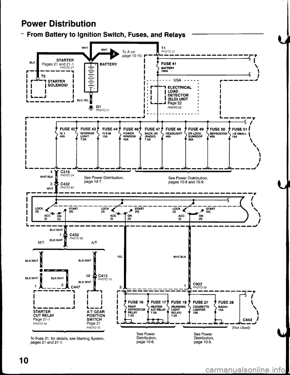
Power Distribution
- From Battery to lgnition Switch, Fuses, and Relays
T1
STARTERPages 21 and 21-1PHOfa 27
FUSE 42tGt
c216
STARTER
| | soLENorD
tlL--J I--------J BLKTYEL
I- G1
I
ILI (ELD} UNITI Page 22
I LOAD: DETECTOR
ELECTNICAL
PHOTO 23
BATTEFYFUSE 4tBATTEAYtmA
,
I
I
L-----?
I
FUSE 43IMTEFIOBLIGHT7.5A
FUSE 44FI E/M15A
FUSE 46FUSE 47AACK UE(RAOTO)7.la
FUSE 48NEADLIGHTFUSE 49DA LOCK,su{BooF304
FUSE 50OEFFOSTERruse sr I+B suaLl I
\
I
I
WH'/BLKSee Power Distribution,pages 1Gg and 10-9.c432
I
\
BLK/WHT'I
Mff BLK/wHr
c432
".__",x'
c922
FUSE I8(aurxf{GIIGHTRE!AY)7.54
FUSE 27C|GAAETTELG}T'ER104
FUSE 28RADIO
f.--
r(
l*,)
See PowerDistribution,page 10-6.
See PowerDistribution,page |0-5.
--':'[E
I
IL------STARTERCUT RELAYPage 21 -1
To Fuse 31, tor details, see Starting System,pages 21 and 21-1.
See Power Distribution,page 10'7.
lff- (".-
r-r
tili*lff* r
acc{r)
FUSE 16AEAAOEFFOSTEAFELAY7.54
If"a*t "t I
i
'o f,""f#
"ooi'*
*"'
i.t r+t
ttl
trlJ L--JA/T GEARPOStTtONswtTcHPage 21PHA|A 7A
10
(Not Used)
Page 1409 of 1681
I
I
I
IJ
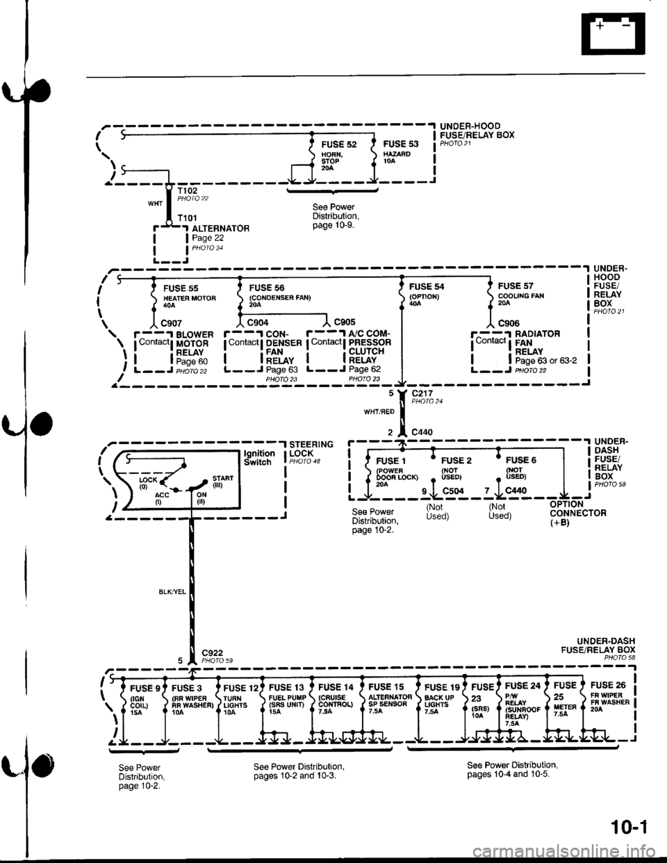
UNDER-HOODFUSE/RELAY BOXI
\
\.t)-
FUSE 528OFN,STOP
FUSE 53HAZARO
I'_'I ALTERNATOB
See PowerDistribution,page 10-9.
| | Pase 22
| | PHoro 31
L--J
1102
T101
FUSE 55HEATEF MOTOB
UNDEB.HOOOFUSE/RELAYBOX
FUSE 56(CoNDENSEA FAtl)204
c904
FUSE 13FUELPUTiP(sB6 UNrr)
I
I
tc907
r--'t BLowER\. tContactl MO-IOR
!ilF"'s?60RELAYI rdq€ @I L--J eudro zz
FUSE 54{oFnon)
."-'1tr;'
FUSE 57COOUNG FAX204
c9)6
r^- -:I RADIATOR
!"o"'""' ! Etto"! | Page 63 or 63.2L--J Pqofo ?2
c90s
r--1coN- r--1A'/CCOM-I Contactl DENSER I Contactl PRESSOR
! IFAN : ; CLUTCNI I RELAY I I RELAYL - - J Page 63 L--J Page 62
-- - -'l UNOER-i-
i I ruser ' rusez 'rusEo I if99Ff.
i ) &*'s"-, ,lil?l, , $?'"r I ii,At:
L -J- --- lLg%- ? J..9Yl--:1,- j
se€ Power l[:'^. l[:'^, 3!I$f"totDiskibution. ubEu/ uJcv / (+B)page 10-2.
c922
UNDER.DASHFUSE/RELAY BOXPHOfa 58
,rar ra !t#
i t FUSE st FusE 3I dcr{ rFRwtPE {tG
nn WIPEF
fis., fllo"o.".",
I
FUSE 12TUfNLIGTITSr0A
FUSE 'I5
ALlERNATOf,sP sENSoa7.tA
FUSE 19BACK UPUGHTSt.5a
FUSE 24
REIAY€rrNBooFNEIAY)?.3A
FUSE
25II€TEF7.5A
FF WPEBFA U'ASHEN204
4y--J---J
.l STEERINGI LOCK
I
I
I
J
! -l tanfiton,. ( t--) lsiwitctr
".r\l:'S7ili"'l
lf 0 ltttt I
a------rl-
l;9c* ('-' oa"t0)
--
See PowerDistribution,page 10-2.
See Power Distribution,pages 10-2 and 10-3.See Power Distribution,pages 10-4 and 10"5.
10-1