1998 HONDA INTEGRA lock
[x] Cancel search: lockPage 1553 of 1681
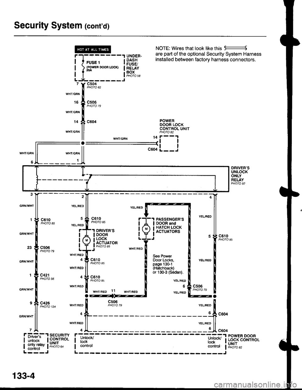
Security System (cont'd)
NOTE: Wires that look like this 5--------J
are part of the optional Security System Harness
WHT/GRN
6
r-l-------1 qrygER- l:Ii:"J u'e vPuv"q' vcvu"rv evole"' ' 'o
I I rus. t i P$38 installed between factory harness connectors'
! l s3*"0*"-* !83f"I I I aoros|LJ-------J, Y9,':A,,,rnr,o"n Iurs I csoe
I PHOfO 79
wnicnr I
r+ f, coor B38"tTo"*II CONTNOL UNITwHr GRN ll PHA|O 82
ll ,n",io"u 11i--l
ll--il-L__J
ll """o"n ll
A_______t_A
DRIVER'SUNLOCKONLYRELAYPHO|O 82
GFNAAIHT
GBNAVHT
GFNrI/VHT
GRNAiVHT
GRNAVHT
:4
;-[
@a
85
79
56
124ll n-o
l1
PASSENGER'SDOOR andHATCH LOCKACTUATORS
Seo PowerDoor Locks,page l3G1(Hatchback)or 1sGg (Sodan).
c610
VEL/BED
6
YEVREO
r ii.#:,:.'r sEcuRrw r;-_=----- ----=:-.r powER DooR
| ilril'ir- | fi$,ynol I unrucn/ l:nl@v I Lo.cK coNrRoL
| ::1ffi1"v l;;6ib" I contror controt liri6'ibazL---J L------- _____J
133-4
Page 1554 of 1681
- How the Circuit Works
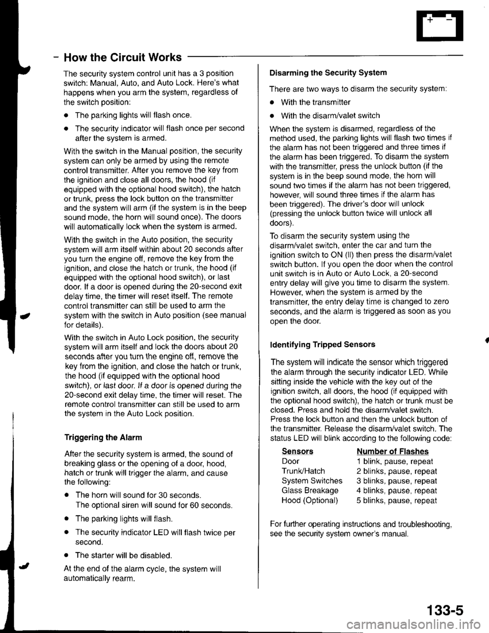
The security system control unit has a 3 position
switch: Manual. Auto. and Auto Lock. Here's what
happens when you arm the system, regardless ol
the switch position:
o The parking lights will flash once.
. The security indicator will flash once per second
after the system is armed.
With the switch in the Manual position, the security
system can only be armed by using the remote
control transmitter, After you remove the key from
the ignition and close all doors, the hood (if
equipped with the optional hood switch), the hatch
or trunk. Dress the lock button on the transmitter
and the system will arm (if the system is in the beep
sound mode, the horn will sound once). The doors
will automatically lock when the system is armed.
With the switch in the Auto position, the security
system will arm itself within about 20 seconds after
you turn the engine off, remove the key from the
ignition, and close the halch or trunk, the hood (if
equipped with the optional hood switch), or last
door. lf a door is opened during the 2o-second exit
delay time, the timer will reset itself . The remote
control transmitler can still be used to arm the
system with the switch in Auto position (see manual
for details).
With the switch in Auto Lock position, the security
system will arm itself and lock the doors about 20
seconds after you turn the engine of{, remove the
key from the ignition, and close the hatch or trunk,
the hood (if equipped with the optional hood
switch), or last door. lf a door is opened during the
2o-second exit delay time, the timer will reset. The
remote control transmitter can still be used to arm
the system in the Auto Lock position.
Triggering the Alarm
After the security system is armed, the sound ot
breaking glass or the opening of a door, hood,
hatch or trunk will trigger the alarm, and cause
the following:
r The horn will sound for30 seconds.
The optional siren will sound lor 60 seconds.
. The parking lights will flash.
. The security indicator LED will flash twice per
second.
. The starter will be disabled.
At the end of the alarm cycle, the system will
automatically rearm.
Disarming the Security System
There are two ways to disarm the security system:
. With the transmitter
o With the disarm/valet switch
When the system is disarmed, regardless of the
method used, the parking lights will flash two times if
the alarm has not been triggered and three times if
the alarm has been triggered. To disarm the system
with the transmitter, press the unlock button (if the
system is in the beep sound mode, the horn will
sound two times if the alarm has not been triggered,
however, will sound three times if the alarm has
been triggered). The driver's door will unlock
(pressing the unlock button twice will unlock all
doors).
To disarm the security system using the
disarm/valet switch, enter the car and turn the
ignition switch to ON (ll) then press the disarm/valet
switch button. lf you open the door when the control
unit switch is in Auto or Auto Lock, a 2o-second
entry delay will give you time to disarm the system.
However, when the system is armed by the
transmitter, the entry delay time is changed to zero
seconds, and the alarm is triggered as soon as you
oDen the door.
ldentifying Tripped Sensors
The system will indicate the sensor which triggered
the alarm through the security indicator LED. While
sitting inside the vehicle wlth the key out of the
ignition switch, all doors, the hood (if equipped with
the optional hood swilch), the hatch or trunk must be
closed. Press and hold the disarm/valet switch.
Press the lock button and then the unlock button of
the transmitter. Belease the disarm/valet switch. The
status LED will blink according to the following code:
Sensors
Door
Trunk/Hatch
System Switches
Glass Breakage
Hood (Optional)
Number ol Flashes
1 blink, pause, repeat
2 blinks, pause, repeat
3 blinks, pause, repeat
4 blinks, pause, repeat
5 blinks, pause, repeat
For further operating instructions and troubleshooting,
see the security system owner's manual.
133-5
Page 1556 of 1681
![HONDA INTEGRA 1998 4.G Workshop Manual lnterlock System
- 98-99 Models
l
HxPS*. !Til;;----
-i yxRi*I DASH I / rulE rz I HOOD
i[EiF,, i]!orn.o" Bli;;1il ilEjii
!s?T"., Lt::-s::3L j "3T",,. P,vu,d Lg _ _ Lt av ^rra: 8Y C216 16I wx HONDA INTEGRA 1998 4.G Workshop Manual lnterlock System
- 98-99 Models
l
HxPS*. !Til;;----
-i yxRi*I DASH I / rulE rz I HOOD
i[EiF,, i]!orn.o" Bli;;1il ilEjii
!s?T"., Lt::-s::3L j "3T",,. P,vu,d Lg _ _ Lt av ^rra: 8Y C216 16I wx](/manual-img/13/6069/w960_6069-1555.png)
lnterlock System
- '98-'99 Models
'l
HxPS*. !'Til;;----
-''i yxRi*I DASH I / rulE rz I HOOD
i[EiF,, i]!orn.'o" Bli;;1il ilEjii
!s?T"., Lt::-s::3L j "'3T",,. P,v'u,d Lg _ _ Lt av ^rra: 8Y C216 16I wxlcnr,r PHora 24
J!^_YEUBLI
UNOER.OASHFUSE/RELAYBOX
c440
c432
ll S€o Power Diskibution,I page 10-9.
,n"tto"" I
1c,u'"" 11 | sa31F-I''I BRAKE SWITCH T--1 THROTTLE
I I closed wrth brake | 5"ns6, I lg.qLrlgN fiP)
lq-]J 1"""",i:;*""* t iii*' i "s'H39*
:ilH1fti$;",,"
;lX *Tt r#i*f= ft;1uii,'" 11? I ;:: [S[l 5p,[,"f*,,*""*l
;ny,t;sfl E?[T
l-T;l'"
t, L- t''""t'1"' ---C "0.,, to"-t' I
STEEBINGLOCK
r-=KeyInlerlockSwitchClosed withkey pushsd.
KeylnterlockSolenold
'" I--j"$t'U"t--:t "o', 3*".''
'f 'o"
i
-
r-, gEr-
- - -;;; - - - -: t rmrsu tsstot't ll
L$'e: 1ui ifiin?rri!::::
I
:- - _ _ _ _::{ : _ _ _ _ _ _ __ - - - J "",.
-JWHT]"TEL
INTERLOCKCONTROLUNIT
;,-".t^-l[-
-------;;f[ ":'"'"."'
seeA/rGearr A c+sg ar< Posnon
wHr BL( [ ero'o i28 cn1,,rvxr ll Indicalor
r* "o"* rz | g+r.q -,
l,/ |Bi*:yJL,tx o"nf'$y:-----1a"r.EAR
I G-11 sh,ft rever push ! | "- i a.o, I P/,oSlTloN swlTcH
-il,tii,oJ,tu"o.""""0 | ^ll \, | -'
-iJcni.'
!"L-----. i, !
'g",J"T,F;:'A$l"Y"";%,r, i" ---1 'r a solenord flom enelgrTing
"'^l '";;'"-
R:":.Rt?i# i F 33""'?Ji"" i ::f;',3J3u:"00":"":Ji",",",a-< 3l'Jlilgl L___+_::':_j ;;ff;;;;rr"p,".."dBLK I NOTE: In case olBLK I NOTE: In case ot syslem
Y r ! ccro malfunchon lhesh1fllever
I ",, I paoro to can be released byI --' I oushino the ionition kev
J---r"?r-"*l-f----) Distribution,
I oaoe to-o.
I ruse aa flNTERLocK uNrn( r.5^
i.- - ---- -
Koy Int6rlockCircuitAllows key inlerlocksolenoid to boenergized unlessshift lever is in "P'
138
f __ --__l pushing lhe ignition key
,lt--- il'""J1:oi:'""i,:"0'"d'l-' c4ol
Page 1557 of 1681
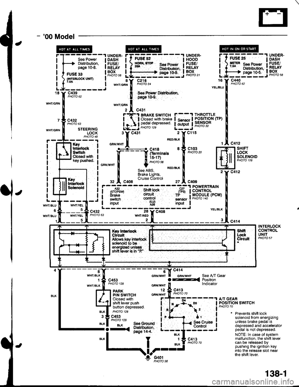
- '00 Model
I
I
FUsg 52I56€ Pow€r Ilxrtdhxbn, :g9:t"t:.i
UNDER.HOODFUSEiRELAYBOXPHOfO 21
Sse Power I DASHDlslribution, : FUSE/page 1G8. I RELAY
c440
c432
WHT/GFNSTEERINGLOCK
rry Ihtsdock :Suhch IClos€d with Il(ey pusned. I
I
I
I
I
I
I
c432
It
I
I
l-
WrtT/BLU
WHT/BLU
KryIr$rdockSdanold
c412-l SHIFT
, I LOCKI I SOLENOIDI lcuoto tzo
Jc412
c414
rAc4
m2Y c4
INtl
.-, I
i/BLX U
-rl"o
POWERTRAINCONTROLMODULE(PCM)
YEVBLX
INTERLOCKCONTROLUNIT
"-*;.'l[-
- - - - - - - -;*f-tr "'"'"'"-,,
r I casr a4
""""#"J;:.
_^ ll"ij*sa*,"
l4J $l't'"ii,''F:^,
*"T't. 3il1;'
;fi;ifJ,t""**o
i"'f- .
*1'
S€e A,/T GsarPositionlndicator
"liiffo,,' a"-BLK I 506 Grourd I-i-. ;*'o' ---;
*"1
I "l! s'*l'"-
Prevents shift locksolenoid trom energizingunless brake pedal isdepressed and acceleratorpedal is not depressed.
NOTE| In case of systemmalfunction, the shilt levercan be released bypushing the ignition keyinto the release slot nearthe shift lever
$l;---l UiSi'"
BRAKE SWITCH F--.t THROTTLE
;'3i:g*s::: !.mnj iffibr-
*,
,V-I'c4ol: PHoro s6
138-1
Page 1558 of 1681
lnterlock System
- How the Circuit Works
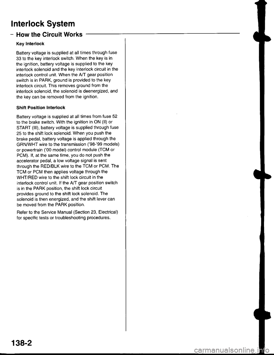
Key Interlock
Battery voltage is supplied at all times through f use
33 to the key interlock switch. When the key is in
the ignition, battery voltage is supplied to the key
intedock solenoid and the key interlock circuit in the
interlock control unit. When the A/T gear position
switch is in PABK, ground is provided to the key
interlock circuit. This removes ground from the
interlock solenoid, the solenoid is deenergized, and
the key can be removed from the ignition.
Shift Position Interlock
Battery voltage is supplied at all times lrom fuse 52
to the brake switch. With the ignition in ON (ll) or
START (lll), battery voltage is supplied through luse
25 to the shift lock solenoid. When you push the
brake pedal, battery voltage is applied through the
GRN/VVHT wire to the transmission ('98-�99 models)
or powertrain ('00 model) control module (TCM or
PCM). lf, at the same time, you do not push the
accelerator pedal, a low voltage signal is sent
through the RED/BLK wire to the TCM or PCM. The
TCM or PCM then applies voltage through the
WHT/RED wire to the shift lock circuit in the
interlock control unit. lf the A,/T gear position switch
is in the PARK position, the shift lock circuit
provides ground to the shift lock solenoid. The
solenoid is then energized, and the shift lever can
be moved from the PARK Dosition.
Refer to the Service Manual (Section 23, Electrical)
for specific tests or troubleshooting procedures.
138-2
Page 1565 of 1681
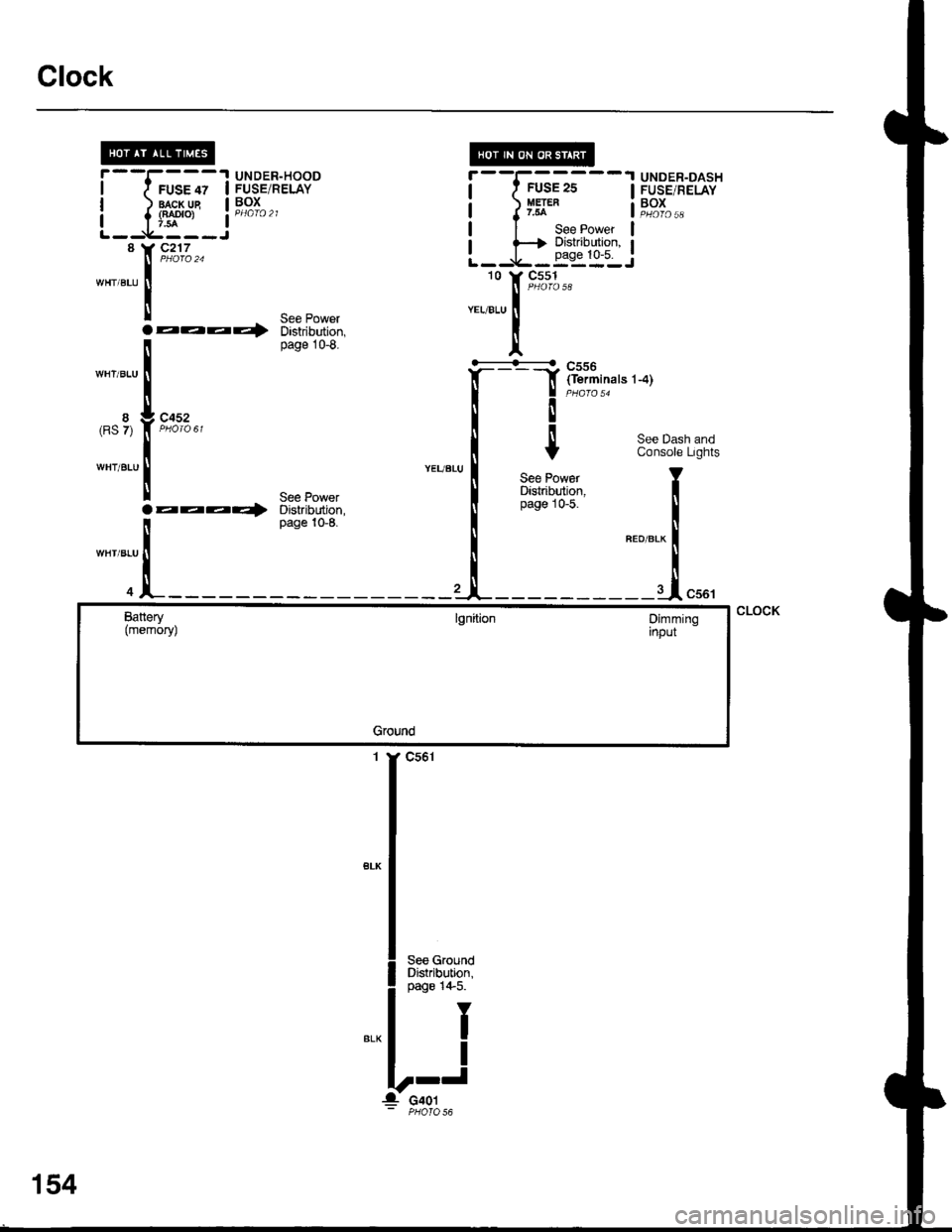
Clock
I
I
8(RS 7)
WHT/BLU
UNDER-HOODruse lz I FUSE/RELAY
lragr-lle I Pg^I^ ^
{f*'o, a PHafo 21
c2'17
aaaQ
c452
aaaa)'
"-,,[r*"
nnT,i"".'-.)
I
Y
See PowarDistribution,page 10-5.
r--I------1 UNDER-DASHI f FUSE2S I FUSE,RELAY
a J y5t* a"';L,,
| | See Power l
r f+ ?:"i:q*t:"' IL--9,-.-=:-:J10 Y C551
8
WHT/BLU
WHT/BLU
See PowerDistribution,page 10-8.
WHT/BLU
See PowerDistribution,page 10-8.
See Dash andConsole Lights
T
I
"ao,"a* f
--J"*'
CLOCKBattery(memoryJlgnitionDimminginput
Ground
1 Y C561
',54
Page 1592 of 1681
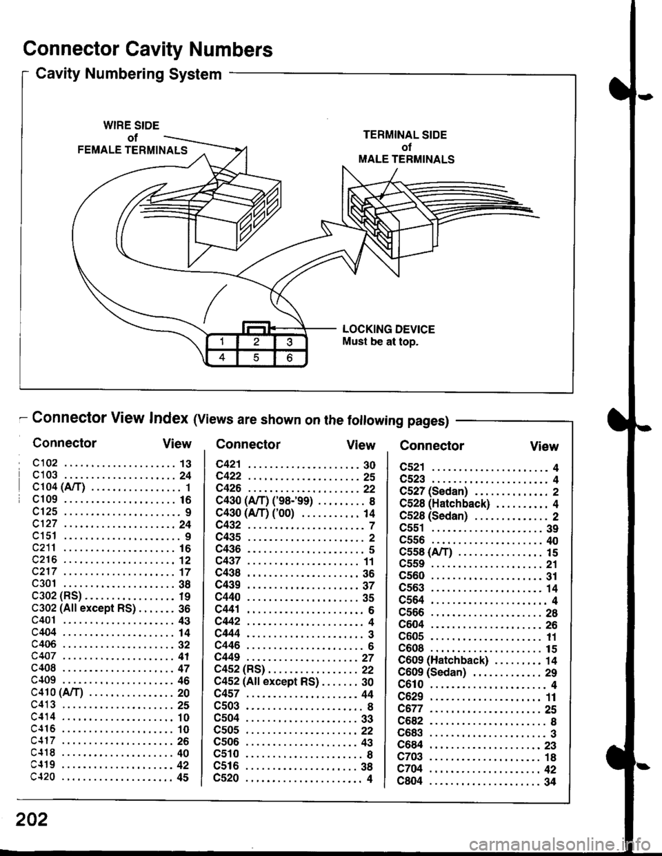
Connector Cavity Numbers
Cavity Numbering System
WIRE SIDE
of
FEMALE TERMINALS
LOCKING DEVICE
Must be at top.
- Connector View lndex (Views are shown on the following pages)
ConnectorView ConnectorView Connector
c521 ...................... 4
c523 ...................... 4
C527 (Sedan) .............. 2
C528 (Hatchback) .......... 4
C528 (Sedan) .............. 2
c551 ..................... 39
c556 ..................... 40
c5s8 (A/T) ....... 15
c559 . . ...... ............, 21
c560 ..................... 31
cs63 .... ...... 14
c564 ... ......... 4
c566 ..................... 28
c604 ..................... 26
c605 ... ....... 11
c608 ... ......... 15
C609 (Hatchback) ......... 14
C609 (Sedan) ............. 29
c610 ...................... 4
c629 ..................... 11
c677... ......25
c682 ... ........ 8
c683 ...................... 3
C684 ..................... 23
c703 ... ....... 18
c704 . .. ......... 42
c804 ..................... 34
View
202
Page 1598 of 1681
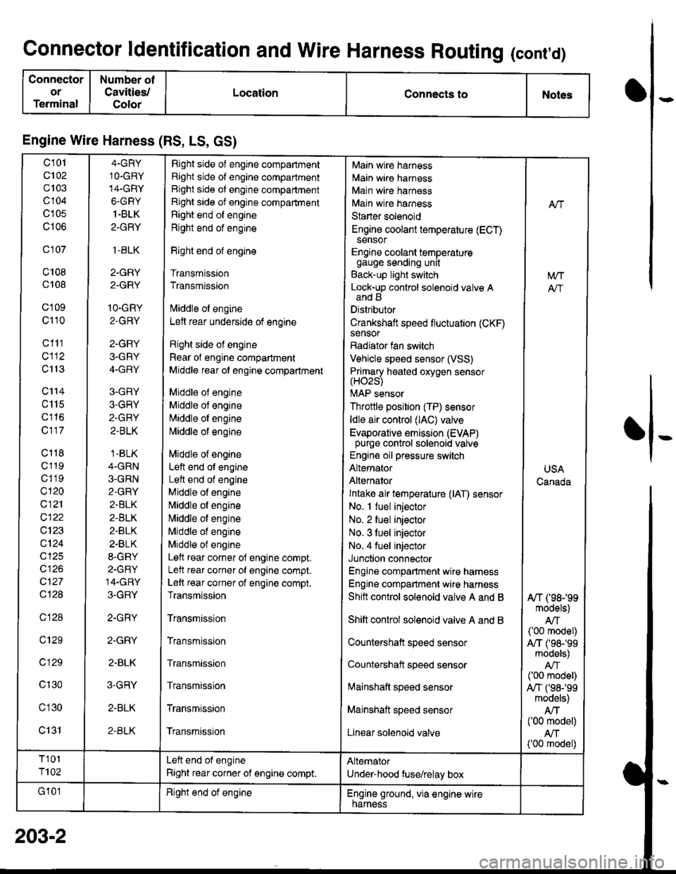
Connector ldentification and Wire Harness Routing (cont,d)
Connector
or
Terminal
Number ot
Cavities/
Color
LocationConnects toNotes
Engine Wire Harness (RS, LS, GS)
c101
c102
c103
c104
c105
c106
c 107
c108
c108
c'1 09
c110
c111
cl12
c113
c'114
c115
c116
c117
c118
c119
c1 19
c120
c121
c122
c123
c124
cl25
cl26
c127
Ql28
c128
c129
c 129
c130
c'l30
c131
4.GRY
1O.GRY
14-GRY
6-GRY
1.BLK
2-GRY
,1-BLK
2-GRY
2.GRY
1O-GRY
2-GRY
2-GRY
3-GRY
4-GRY
3-GRY
3-GRY
2-GRY
2.BLK
.1-BLK
4-GRN
3-GRN
2-GRY
2.BLK
2-BLK
2-BLK
2.BLK
8-GRY
2-GRY
14-GRY
3-GRY
2.GRY
2.GRY
2-BLK
3-GRY
2-BLK
2-BLK
Right side of engine compartment
Right side of engine compartment
Right side ot engine compartment
Right side of engine compartment
Right end of engine
Right end of engine
Right end of engine
Transmission
Transmission
lvliddle ol engine
Lett rear underside of engine
Right side ol engine
Rear of engine compartment
Middle rear ol engine compartment
Middle ol engine
Middle of engine
Middle ol engine
l\4iddle of engine
Middle of engine
Left end ot engine
Lett end of engine
Middle of engine
N,liddle ol engine
Middle of engine
Middle of engine
Middle of engine
Left rear corner of engine compt.
Lelt rear corner of engine compt.
Left rear corner of engine compt.
Transmission
Transmission
Transmission
Transmission
Transmission
Transmission
Transmission
Main wire harness
Main wire harness
Main wire harness
Main wire harness
Starter solenoid
Engine coolant temperature (ECT)sensor
Engine coolant temperaturegauge sending unit
Back-up light switch
Lock-up control solenoid valve Aand B
Distributor
Crankshaft speed fluctuation (CKF)sensor
Radiator fan switch
Vehicle speed sensor (VSS)
Primary heated oxvoen sensor(H02s)
MAP sensor
Throttle position (TP) sensor
ldle air control (lAC) valve
Evaporative emission (EVAP)purge control solenoid valve
Engine oil pressure switch
Alternator
Alternator
Intake air temperature (lAT) sensor
No. I fuel injector
No. 2 fuel injector
No. 3 tuel injector
No. 4 fuel injector
Junction connector
Engine compartment wire harness
Engine compartment wire harness
Shitt control solenoid valve A and B
Shift control solenoid valve A and B
Countershaft speed sensor
Countershatt speed sensor
lvtainshatt speed sensor
Mainshaft speed sensor
Linear solenoid valve
NT
[/VT
A"/T
USA
Canada
A/T (98199models)
AIT('00 model)
A,/T ('98-'�99models)
('00 model)
A,/T f98-'99models)
Atf('00 model)
AN('00 model)
T101
T102
Left end of engine
Right rear corner of engine compt.
Alternator
Under-hood fuse/relay box
G'101Right end ot engineEngine ground, via engine wirenarness
o
I
203-2