Page 1197 of 1681
A/T Gear Position Indicator
Component Location Index
GAUGE ASSEMALYRemoval, page 23-126Disassembly, page 23-127Bulb Locations, page 23-122INTERLOCK SYSTEMDescription, page 23-'147A/T GEAR POS]TIONINDICATORInput Test, page 23-142
A/T GEAR POSTTION SWITCHTest, page 23-144R6olacement, section 14
:S
23-140
Page 1198 of 1681
Circuit Diagram
)
{
{
I
UNDER-HOOD FUSEiRELAY 80XIGN TIONSWITCHUNDER-DASHFUSE/RELAY BOX
. TRANSMISS]ONCONTROLMODULE (TCM)
/;; l-^--;;;;lw--BLh ---wrl f ,:+ BLK/E- t.d\o-ft\---l
I t,;:'*'
IVECM
f7
ILT GRN/BLK
YEUBLU
(n lhe gauqe assembly)D4
TRANSMISSIONCONTROLMODULErrcM)
f7
IIGRN/BLK
c6c7c8 lc9NTERLOCKCONTROLUNIT (
f7
IGRNMHT
BLK
TRANSMISSION CONTROLMODULE TICM)GRNCRN]BLULTGRNMHT
GRN/YEL
No l9 (104)FUSE
f7
IRED/BLK
A?TGEARPOSITION SWTCHRED
II
I
Y?
DASH LIGHTSBFIGHTNESSCONTROLLER
BLK
oro,G40lG20lG401
A/T GEAH POSITION NDICATOR DIMMING C RCUIT
A/T GEARPOS TIONCONSOLELIGHT(1.4w)
/ ,/ t2
{,
23-141
Page 1202 of 1681

Replacement
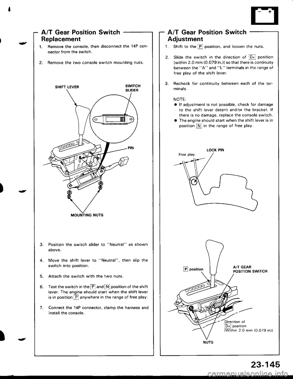
1. Remove the console. then disconnect the 14P con-
nector from the switch.
2. Remove the two console switch mounting nuts.
3.
1.
Position the switch slider to "Neutral" as shown
above.
Move the shitt lever to "Neutral", then slip the
switch into position.
Attach the switch with the two nuts.
Test the switch in the @ and I position of the shift
lever. The engine should start when the shift lever
is in position E anywhere in the range of free play.
Connect the l4P connector, clamp the harness and
install the console.
5.
)
-
A/T Gear Position SwitchA/T Gear Position Switch
Adjustment
1. Shitt to the @ position, and loosen the nuts.
2. Slide the switch in the direction of @ position
lwithin 2.0 mm (O.079 in.)l so that there is continuity
between the "A" and "L" terminals in the range oI
free play oI the shift lever.
3. Recheck for continuity between each of the ter-
manals.
NOTE:
a ll adjustment is not possible, check for damage
to the shift lever detent and/or the bracket. lf
there is no damage, replace the console switch.
a The engine should start when the shift lever is in
position S in the range of free play.
E position
)
LOCK PIN
'/ia
NUTS
23-145
Page 1203 of 1681

Interlock System
Component Location Index
Description
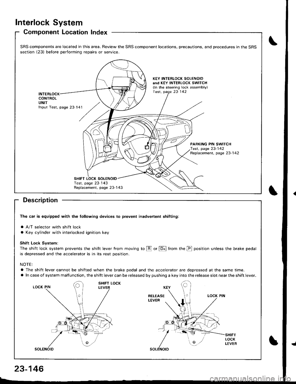
The car is equipped with the lollowing devices to plevent inadvertent shifiing:
a A/T selector with shift lock
a Key cylinder with interlocked ignition key
Shift Lock Svstem:
The shift lock system prevents the shilt lever trom moving to @ or [6ol from the p position unless the brake pedal
is depressed and the accelerator is in its rest position.
NOTE:
a The shift lever cannot be shifted when the brake pedal and the accelerator are depressed at the same time.
a In case of system malfunction, the shift lever can be released by pushing a key into the release slot near the shift lever.
SRS components are located in this area. Review the SRS component locations, precautions, and procedures in the SRS
section (23) belore performing repairs or service.
KEY INTERLOCK SOLENOIDand KEY INTERLOCK swlTCH
{ln the steering lock assembly}
INTERLOCKCONTROLUNIT
PARKING PIN SWITCHTest, page 23-142Replacement, page 23-1 42
Replacement, page 23-143
SHIFT LOCK SOL€NOIDTest, page 23 143
23-146
Page 1204 of 1681
)
t
t
Description
Ths cal is equipped with the tottowing devices to prevent inadvertenl shifting:
a Key cylinder with interlocked ignition key (Key Interlock System)
a shift lever with shift lock (shilt Lock system)
Key Interlock System:
When the shift lever is in any other position than @ or is not securely locked in @ (parking pin switch is ON), a solenoid
is activated, making it impossible to remove the ignition key from the ignition switch.
To be able to remove the key, the shift lever must be in E] and must be securely locked in this position {parking pin
switch must be turned oft by the lock pin)
The shift lever is in any othel position than El and the psrking pin switch is ON:
CYLINDER
The shitt lever is in l!] and the parking pin switch is OFF:
KEY CYLINOER
PARKING PIN
SHIFT LOCK LEVER
SHIFT LOCK LEVER
{t
23-147
Page 1205 of 1681
lnterlock System
Circuit Diagram
NOTE: Different wires with the same color have been given a number suflix to distinguish them (for example,cRNA/VHT I and cRNMHT '� are not the same).
WHT/ BLK .-- WHI
cnrruvgr'
+. BRAKE LIGNTS.CSUISE CONTROLUNIT. ABS COIITROL UNIT' ECM
INTEBLOCKCONTROLUNIT
A]'IGEARPOStTIONINOICATOR
v
t,
UNDER-HOOO FUSEi RELAY BOX
N0.41 (100A) N0.42 (404)
YEUBLUcnrivrr '
WHT/BLU
KEYINTERLOCKswtTcH
THBOTTLEPosrT|0N (TP)SENSOR
f7
IRED/BLK
(Cjl :in posiron E t
23-14A
Page 1206 of 1681

){r/
Control Unit Input Test
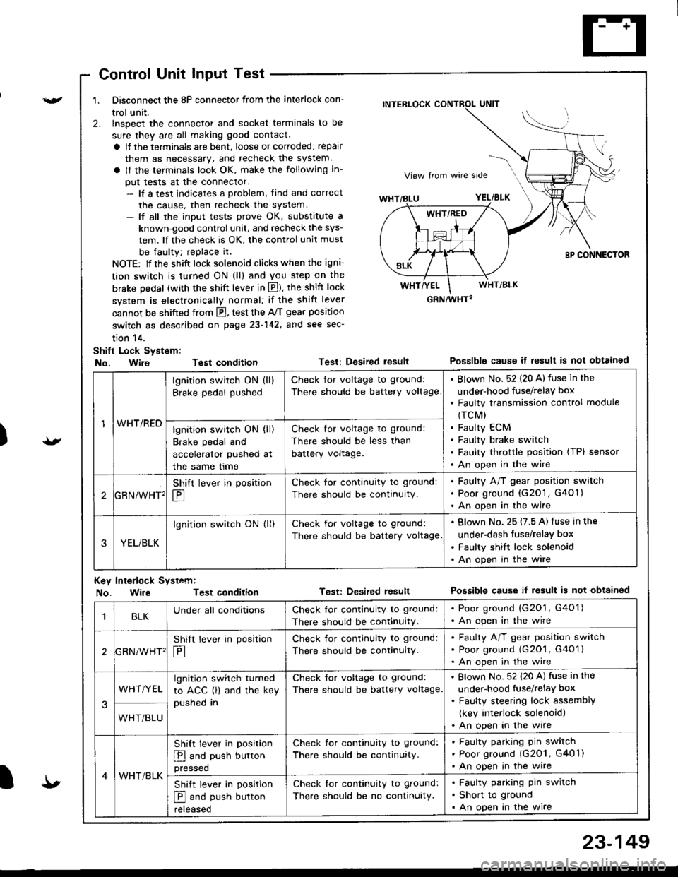
1. Disconnect the 8P connector from the interlock con-
trol unit.
2. lnspect the connector and socket terminals to be
sure they are all making good contact.
a It the terminals are bent, loose or corroded, repair
them as necessary, and recheck the system.
a lf the terminals look OK, make the following in-
put tests at the connector.- lf a test indicates a problem, tind and correct
the cause, then recheck the system.- lf all the input tests prove OK, substitute a
known-good control unit, and recheck the sys-
tem. lf the check is OK, the control unit must
be faulty; replace it.
NOTE: lf the shift lock solenoid clicks when the igni-
tion switch is turned ON (ll) and you step on the
brske Dedal (with the shift lever in E). the shift lock
system is electronically normal; if the shift lever
cannot be shifted from fl, test the 46 gear position
switch as described on page 23-142, and see sec-
tion 14.
Shift Lock System:
No. Wire Test condition
No. WireTest condition
Test: Desired resultPossible causs it result is not obtained
Test: Dcsired lesultPossible cause it result is not obtainsd
INTERLOCK CONTROL UNIT
GRN/wHT2
1WHT/RED
lgnition switch ON (ll)
Brake pedal pushed
Check for voltage to ground:
There should be battery voltage
Blown No. 52 {20 A) fuse in the
under-hood fuse/relaY box
Faulty transmission control module
(TCM)
Faulty ECM
Faulty brake switch
Faulty throttle position (TP) sensor
An open in the wire
lgnition switch ON (ll)
Brake pedal and
accelerator pushed at
the same me
Check for voltage to ground:
There should be less than
battery voltage.
tGRN/WHT'
Shift lever in position
E
Check tor continuity to ground:
There should be continuity.
Faulty A/T gear position switch
Poor ground {G20'1 , G401)
An open in the wire
3YEL/BLK
lgnition switch ON (ll)Check for voltage to ground:
There should be battery voltage
Blown No. 25 (7.5 A) fuse in the
under-dash fuse/relay box
Faulty shift lock solenoid
An open in the wire
Key Int€rlock Systcm:
BLKUnder all conditionsCheck lor continuity to ground:
There should be continuitY.
. Poor ground (G201, G401). An open in the wire
GRNiWHT'
Shift lever in position
E
Check for continuity to ground:
There should be continuity.
Faulty A/T gear position switch
Poor ground {G2O1, G401 }
An open in the wire
3
WHT/YELlgnition switch turned
to ACC (l) and the key
pushed in
Check tor voltage to ground:
There should be battery voltage.
Blown No. 52 (20 A) fuse in the
under-hood fuse/relaY box
Faulty steering lock assemblY
(key interlock solenoidl
An open in the wireWHT/BLU
4WHT/BLK
Shift lever in position
E and push button
pressed
Check for continuity to ground:
There should be continuity.
Faulty pafking pin switch
Poor ground (G2O1, G4O 1)
An open in the wire
Shift lever in position
E and push button
reteaseo
Check for continuity to ground:
There should be no continuity.
Faulty parking pin switch
Short to ground
An open in the wire
I'
23-149
Page 1207 of 1681

Interlock System
Key Interlock SolenoidTest
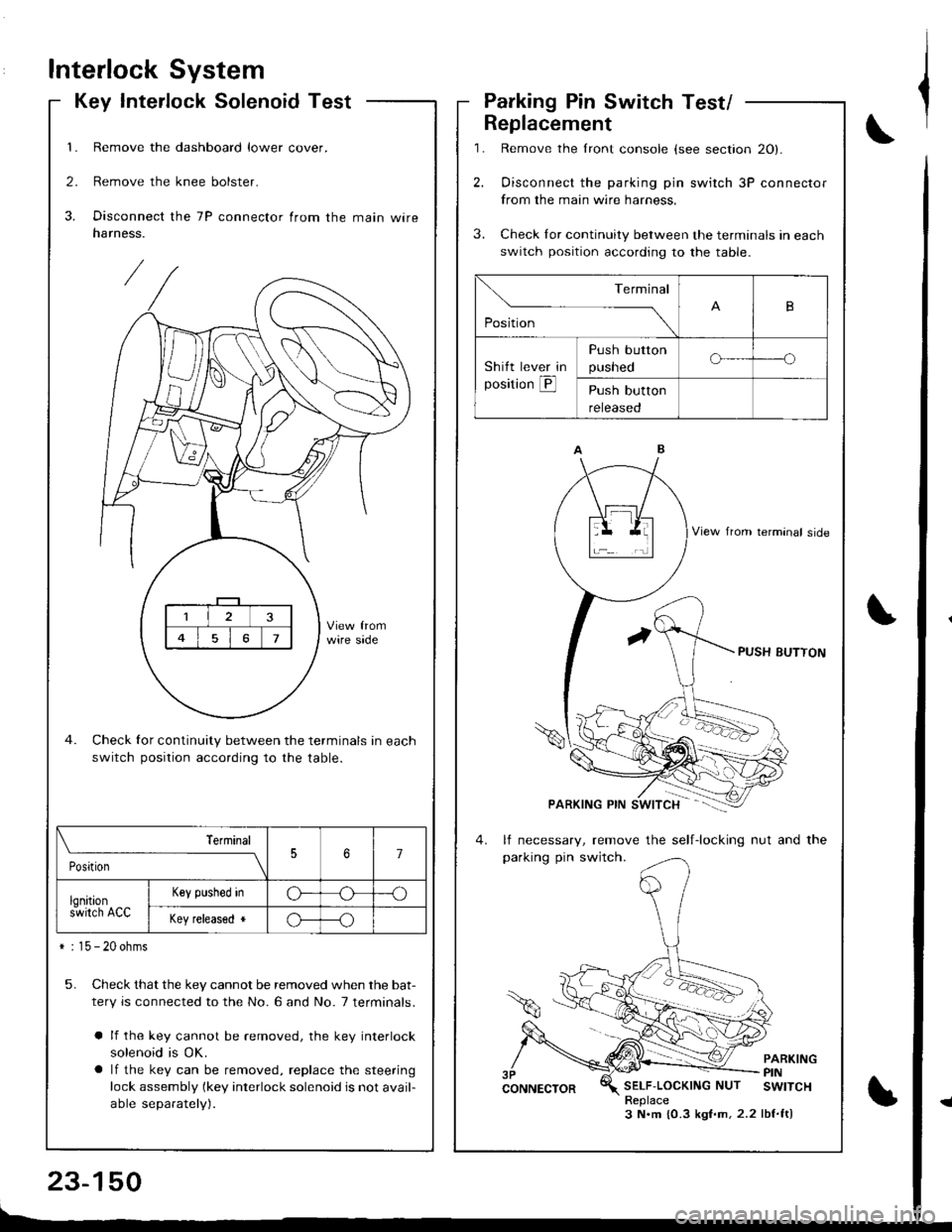
1. Remove the dashboard lower cover.
2. Remove the knee bolster.
3. Disconnect the 7P connector from the main wireharness.
Check for continuity between the terminals in each
switch position according to the table.
5. Check that the key cannot be removed when the bat-
tery is connected to the No. 6 and No. 7 terminals.
a lf the key cannot be removed, the key interlock
solenoid is OK.
a lf the key can be removed, replace the steering
lock assembly (key interlock solenoid is not avail-
able separately).
\_____,___ ___l
PositionJ7
lqnitions-wirch ACC
Key plshed inG---o
Key released *o---o
* : 15 - 20 ohms
,l
\,
Parking Pin Switch Test/
1.
2.
Replacement
3.
Remove the lront console (see section 20).
Oisconnect the parking pin switch 3P connector
from the main wire harness.
Check Ior continuity between the terminals in each
switch position according to the table.
lf necessary, remove the self-locking nut and the
parking pin switch.
PARKINGPINSELF'LOCKINGNUT SWITCHReplace3 N.m {0.3 kgf.m,2.2 lbf.ft)
Terminal
,o"n*
-- ---_\B
Shitt lever in
position @
Push button
pusneoo-----o
Push button
reteaseo