Page 1135 of 1681

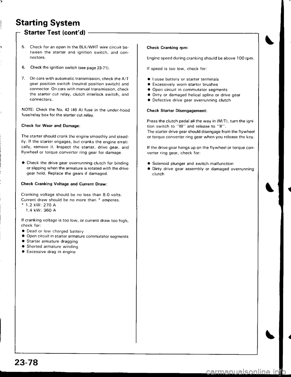
Starting System
Starter Test (cont'dl
Check Cranking rpmr
Engine speed during cranking should be above 1OO rpm.
lJ speed is too low, check for:
a Loose batlery or starter terminals
a Excessively worn starter brushes
a Open circuit in commutator segments
a Dirty or damaged helical spline or drive gear
a Defective drive gear overrunning clutch
Check Starter Disengagement:
Press the clutch pedal all the way in (M/T), turn rhe igni
tion switch to "lll" and release to "11".
The starter drive gear should disengage from the flywheel
or torque converter ring gear when you release the key.
It the drive gear hangs up on the flywheel or torque con-
verter ring gear, check for:
a Solenoid plunger and switch mallunction
a Dirty drive gear assembly or damaged overrunning
clutch
5. Check for an open in the BLK/WHT wire circuit be
tween the starter and ignition switch, and con-
necrors,
6. Check the ignition switch (see page 23-71).
7. On cars with automatic transmission, check the A/Tgear position switch (neutral position switch) and
connector. On cars with manualtransmission, check
the starter cut relay, clutch interlock switch, and
connectors.
NOTE: Check the No. 42 (40 A) fuse in the under,hoodfuse/relay box for the starter cut relay.
Check Jor Wear and Damage:
The starter should crank the engine smoothly and stead,ily. lf the starter engages, but cranks the engine errati
cally, remove it. Inspect the starter, drive gear, andllywheel or torque converter ring gear lor damage.
a Check the drive gear overrunning clutch for binding
or slipping when the armature is rotated with the drivegear held. Replace the gears i{ damaged.
Check CJanking Voltage and Current Draw:
Cranking voltage should be no less than 8.O volts.
Current draw should be no more than * amperes.* 1.2 kW: 27O A
1 .4 kW: 360 A
It cranking voltage is too low, or current draw too high,check for:
a Dead or low charged batterya Open circuit in starter armature commutator segmentsa Starter armalure dragging
a Shorted armature windinga Excessive drag in engine
Page 1136 of 1681
1.Remove the dashboard lower cover and knee bolster(see page 23-71],, then disconnect the 2P connector
from the switch.
Check for continuity between the terminals accord-
ing to the table.
2.
3.ll necessary, replace the switch or adiustthe switch
position (see section 12).
Terminal
cr,t"hP;i
-_\B
RELEASED
PUSHEDoo
Clutch lnterlock Switch TestStarter Solenoid Test
1. Check for continuity between the terminals accord-
ing to the table.
HOLD_ IN COIL
23-79
I
/
-
I
-a
Coil
Teminalt\4sHousing
HOLD INO-o
PULL-INo-o
PULL_ IN COIL
Page 1142 of 1681
BRUSHES
Startel Field Winding Test
Check for continuity between the brushes. lf there's
no continuity. replace the armature housing.
Check for continuily between each brush and the ar-
mature housing (ground). lf there is continuity,
replace the armature housing.
Overrunning Clutch InsPection
Slide the overrunning clutch along the shaft.
Does it move freely? It not, replace it.
Rotate the overrunning clutch both ways.
Does it lock in one direction and rotate smoothly in
reverse? It it does not lock in either direction or it
locks in both directions, repl8c€ it,
lf the starter drive gear is worn or damaged, replace
the overrunning clutch assembly; the gear is not
available separately.
Check the condition ot the flywheel or torque con-
vener ring gear it the starter drive gear teeth are
damaged.
/
J
CLUTCH G€AR
DRIVE GEAR
23-85
l'l- ,-----_ -'l
Page 1165 of 1681
Charging System
Alternator Overhaul
CAUTION: Do not remove the pulley unless the tront
bearing needs replacement.
To loosen the pulley locknut, use 10 mm and 22 mm
wrenches. lf necessary, use an impact wrench.
DENSO:
PULLEY LOCKNUT1'11 N.ft (11.3 kgf.m,82 lbt.ft)
FRONT BEARING
STATOR/DRIVE ENDHOUSINGOENSO:Test, page 23-1'10MITSUBISHIITest, page 23-112
PULLEY
CAUTION: Do not get grease
or oil on the slip rings.
BRUSH HOLDERINSULATOR
offiEND COVER
k-"o*"... ".,"' BRACKET
23-108
L_�
ROTOR
PULLEY
10 mm 8OX WRENCH
BEARING
Page 1166 of 1681

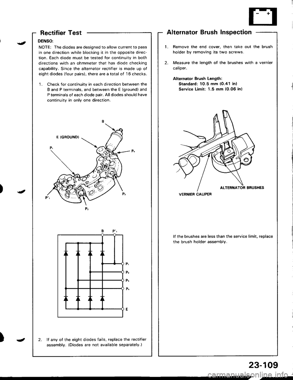
RectifierTest
DENSO:
NOTE: The diodes are designed to allow current to pass
in one direction while blocking it in the opposite direc-
tion. Each diode must be tested tor continuity in both
directions with an ohmmeter that has diode checking
capability. Since the alternator rectifier is made up ot
eight diodes (four pairs), there are a total of 16 checks.
'1. Check for continuity in each direction between the
B and P terminals, and between the E (ground) and
P terminals of each diode pair. All diodes should have
continuity in only one direction.
lf any of the eight diodes fails, replace the recti{ier
assembly. iDiodes are not available separately.)
2.
AlternatorBrushInspection
l.Remove the end cover, then take out the brush
holder by removing its two screws.
Measure the length of the brushes with a vernier
caliper.
Altelnator Brush Length:
Standard: 1O.5 mm {O.41 in}
Service Limit: 1.5 mm (0.06 in)
2.
lf the brushes are less than the service limit, replace
the brush holder assembly.
VERNIER CALIPER)
{
J
)
23-109
J
.-
Page 1169 of 1681

Gharging System
Reetifier Removal (cont'd)
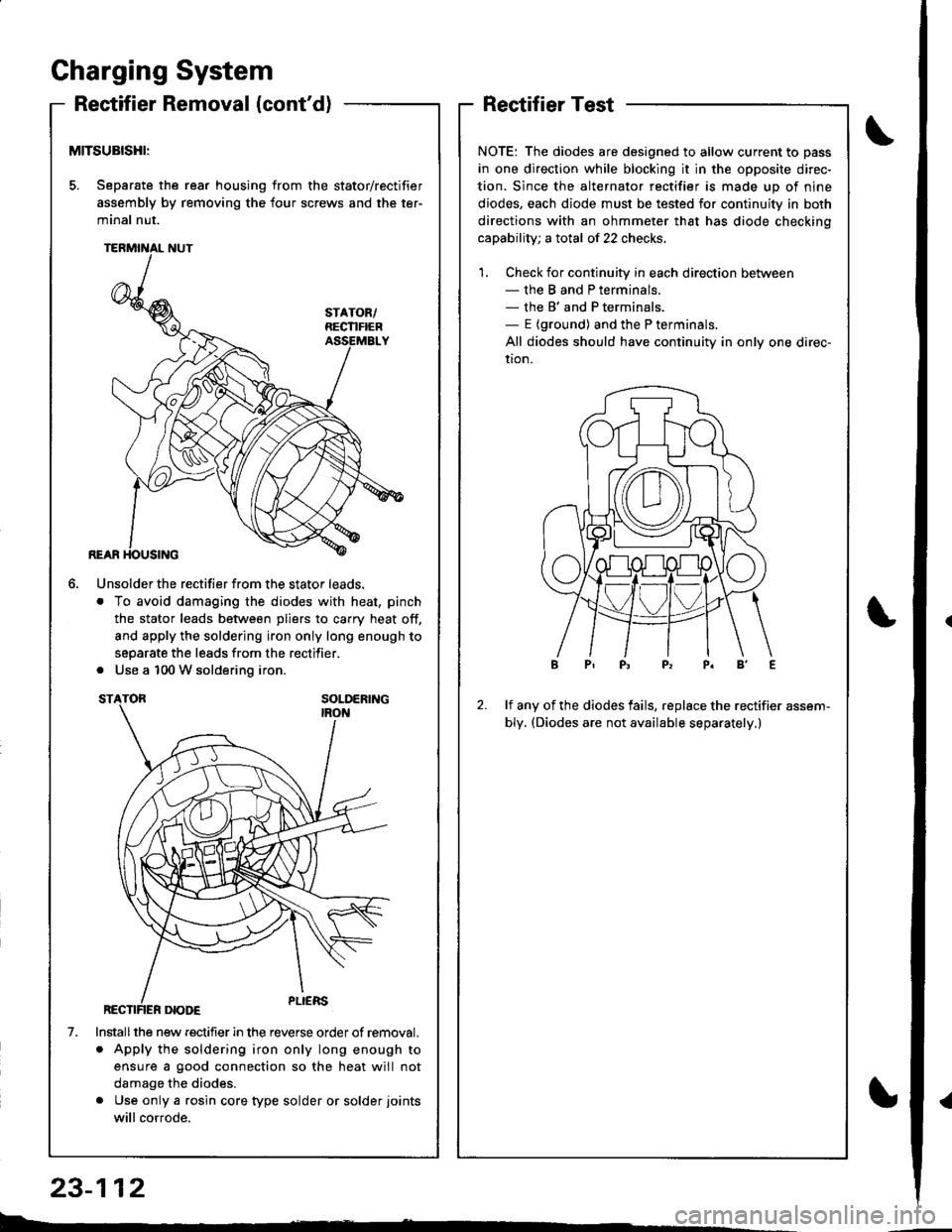
MITSUBISHI:
5. Separate the rear housing from the stator/rectifier
assembly by removing the four screws and the ter-
minal nut.
6.
1.
Unsolder the rectifier from the stator leads.
. To avoid damaging the diodes with heat, pinch
the stator leads between pliers to carry heat off,
and apply the soldering iron only long enough to
separate the leads from the rectifier.
. Use a 100 W soldering iron.
Installthe new rectifier in the reverse order of removal.
. Apply the soldering iron only long enough to
ensure a good connection so the heat will not
damage the diodes.
. Use only a rgsin core type solder or solder joints
will cor.ode.
RectifierTest
NOTE: The diodes are designed to allow current to pass
in one direction while blocking it in the opposite direc-
tion. Since the alternator rectifier is made up of nine
diodes, each diode must be tested for continuity in both
directions with an ohmmeter that has diode checkino
capability; a total of 22 checks.
1. Check for continuity in each direction between- the B and P terminals.- the B' and P terminals,- E (ground) and the P terminals.
All diodes should have continuity in only one direc-
uon.
2.lf any of the diodes fails, replace the rectifier assem-
bly. (Diodes are not available separately.)
b.�
23-112
{
Page 1186 of 1681
Test tho vss:1. Turn the ignition switch OFF.2. Connect the other test harness connector to the VSS.3. Raise th€ front and roar of thevehicle, and support it withsafety stands.4. Put the transmission in neu-tral with the ignition switchoN flr).5. Slowly rotate one wheel withthe other wheel blocked.
Does voltage pulse from 0 toapprox.5 V or more?
Spocdomatcr Te3t:1. Disconnoct the 16P conngctor"B" from the gauge assem-
2. Touch 8 probe to the ORNwire, and connect it to bodyground through a voltmetor.3. Slowly rotate one wheel withthe other wheel blocked.
Repair open in the ORN and BLU/WHT wire botw.en tho VSS .ndthe soa€do-mster.
Does the meter indicate puls-ing voltage?
{
{
WHT TESTCLIP
TEST HABNESSOTLAJ - PT3O2OA
FED TEST HARNESSCLIPGRN TEST HARNESS CLIP
GAUGE ASSEMBLY 16P CONNECTOR '8"
PROTECTIVETAPE
){
Page 1196 of 1681

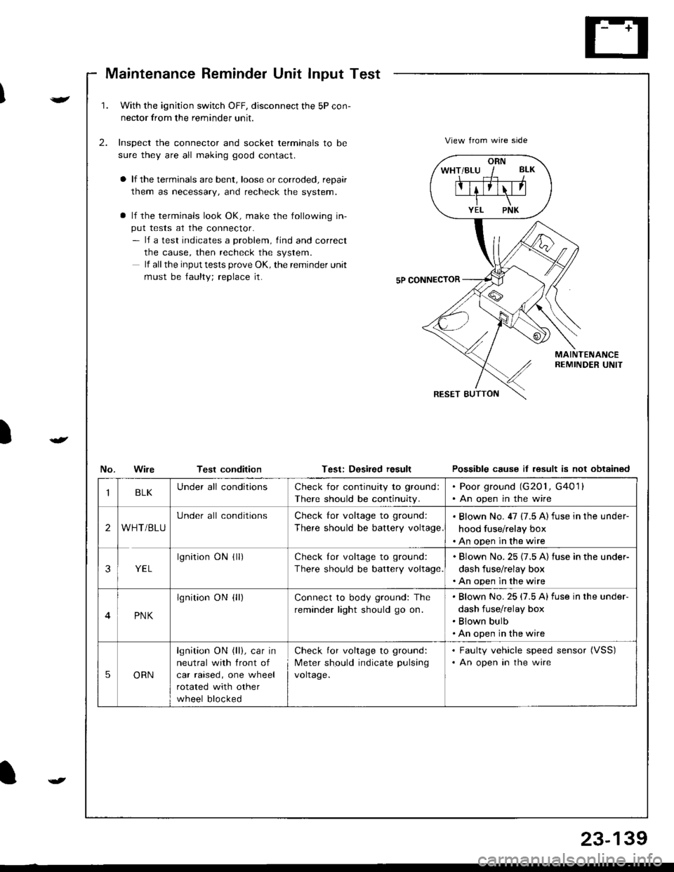
Maintenance Reminder Unit Input Test
)
v
t
1.With the ignjtion switch OFF, disconnect the 5P con-
nector from the reminder unit.
Inspect the connector and socket terminals to be
sure they are all making good contact.
a lf the terminals are bent, loose or corroded, repair
them as necessary, and recheck the system.
a lf the terminals look OK, make the following in-
put tests at the connector.- lf a test indicates a problem, find and correct
the cause, then recheck the system.
lf all the input tests prove OK, the remind€r unit
must be faulty; replace it.
2.View from wire side
MAINTENANCEREMINDER UNIT
No.WileTest conditionTest: Dosired resultPossible cause it lesult is not obtained
ORN
IBLKUnder all conditionsCheck for continuity to ground:
There should be continuity.
. Poor ground (G201, G4011. An open in the wire
2WHT/BLU
Under all conditionsCheck for voltage to ground:
There should be battery voltage
. Blown No. 47 (7.5 A) fuse in the under-
hood fuse/relay box. An open in the wire
3YEL
lgnitionONflr)Check lor voltage to ground:
There should be battery voltage.
. Blown No.25 {7.5 A) fuse in the under-
dash fuse/relay box. An open in the wire
4PNK
lgnition ON {ll)Connect to body ground: The
reminder light should go on.
Blown No.25 (7.5 Alfuse in the under-
dash fuse/relay box
Blown bulb
An open in the wire
5ORN
lgnition ON (ll), car in
neutral with front of
car raised, one wheel
rotated with other
wheel blocked
Check for voltage to ground:
Meter should indicate pulsang
voltage.
. Faulty vehicle speed sensor (VSS)
. An open in the wire
t
23-139