Page 974 of 1681
Trunk Lid Latch and Lock Cylinder
Replacement
JNOTE: Take care not to bend the cylinder rod and trunk
lid opener cable.
1. Disconnect the connector and trunk lid opener cable.
4. Remove the bolt, then pull the lock cylinder out. Re
move the lock cylinder {rom the cylinder rod, then
take them out.
: Bolt location, 1
CONNECIOR
LOCKCYLINDER
r>'
2. Disconnect the cylinder rod.
CYLINDERROD
CYLINOER ROD
5. lnstallation is the reverse of the removal procedure.
NOTE:
a Apply grease to the trunk lid latch.
Remove the bolts, then remove the trunk lid
: Boli locations, 3
TRUNK LIDLATCH
3.latch.
6x1.0mm ILOCK CYLINDER
9.8 N.m 11.0 kgf m, I
:t"r': -/
a
a
a
Make sure the trunk lid locks securely.
N/ake sure the trunk lid opens properly.
Make sure the connector is connected properly.
20-159
Page 976 of 1681
J
Hatch Spoiler
Replacement
NOTE:
a Take care not to scratch the hatch.
a Open the hatch.
1. Remove the hatch side trim and hatch trim panel
{see page 20-148}.
2. Remove the nuts and disconnect the connector.
a: Nut locltion3,4
Type R Model:
a: f{ut locltlona, 4
Apply liquidthread lock.
6 x 1.0 mm9.8Nm
{1.0 kgf m,7.2 tbt.ltl ./CONNECTOR
3. Remove the hatch spoiler by turning the clip nut on
the left side counterclockwise.Apply liquidthread lock.
Installation is the reverse of the removal procedure.HATCH SPOILER
HATCH
6x1.0mm9.8 N.m11.0 kgt.m,?.2 tbt.ftl
4. Installation is the reverse of the removal procedure.
20-161
Page 1012 of 1681
Heater Control Panel
Replacement
J
2.
1.Disconnect the air mix control cable from the heat
er unit (see page 21-27).
Remove the rear window delogger switch and the
hazard warning switch.
Remove the two self-tapping screws, then pull out
the heater control panel and the center air vent. Dis-
connect the connectors, and remove the heater con-
trol panel and the center air vent.
NOTE: The locking tabs of the hazard warning
switch and heater control panel connectors are on
the bottom.
CENTER AIR VENTREAR WINDOWD€FOGGERswtrcH
HAZARDWARNINGswrTcH
CONNECTORS
4. Remove the four self-tapping screws and the center
atr vent.
Install in the reverse order of removal, and adjust the
air mix control cable at the heater unit (see page
21-271.lt necessary, adjust the heater valve cable
lsee page 21-27).
5.
AIR MIX CONTROL CABLE
CENTER AIR VENT
21-25
Page 1013 of 1681
HEATER FAN SWITCHTest, page 21 30
AIR MIX CONTROL CABLEAdjustment, page 21-27
Air Mix Contlol Cable ReDlacement
1. Cut the inner cable on the lever side of the cable
holder, then remove both pieces of the inner cable.
2.Using a shafp knife, cut completely through the end
of the cable housing at the two locations.
Slide the large section of the cable housing out of
the cable holder, being careful not to damage the
cable stops.
Carefully remove the cut pieces of the cable hous
ing with a small tlat tip screwdriver.
Hook the tip of the new air mix cable to the temper-
ature control lever, then push the cable housing into
the cable holder until it locks place.
3.
AIR MIXCONTROLCABLE
5.
NOTEr Atter assembly, check that the temperature control lever slides smoothly through the full stroke from right
to left.
Heater Control Panel
Overhaul
t
21-26
Page 1021 of 1681
lllustrated Index
JSRS components are located in this area. Review the SRS component locations, precautions, and procedures in the SRS
section (23) before performing repairs or service.
EVAPORATORReplacement, page 22,26Ove.haul. page 22-27
SERVICE VAI-VE
ILOW.PRESSURE SIDE)
SERVICE VALVE{HIGH.PRESSUEE SIDE}
SIGHT GLASS
CONOENSERReplacement, page 22 37
A/C PRESSURE SWITCHCOMPRESSOR
When the refrigerant pressure is below 200 kPa (2.0
kgllcm,, 28 psi) due to refrigerant leakage or above 3,'100kPa (32 kgtcm,,460 psi) due to relrigerant blockage, theA,/C pressure sw;tch opens the circuit to the A,/C switch andstops the air conditioning to protect the compressor.
page 22-30
22-3
Page 1038 of 1681
NOTE: The diode is designed to pass current in one
direction while blocking it in the opposite direction.
Use an analog ohmmeter, or a digital ohmmeter
equipped with a diode tester.
Check for current flow in both directions between the A
and B, and B and C terminals. There should be current
flow in only one direction.
DiodeA/C Switch
TestTest
22-20
NOTE: The Ay'C switch contains a diode. Use an analog
ohmmeter, or a digital ohmmeter equipped with a diode
tesler.
Check for current flow in both directions between termi-
nals 11 and 12. There should be current flow in only one
direction.
po";;
ONo
OFF
Page 1052 of 1681

Compressor
a
a
Clutch Overhaul (cont'dl
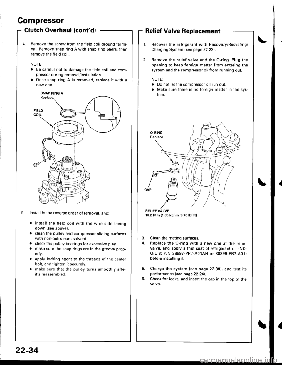
Remove the screw from the field coil ground termi,
nal. Remove snap ring A with snap ring pliers, then
remove the field coil.
. Be careful not to damage the field coil and com-presso. during removal/installation.
. Once snap ring A is removed, replace it with a
SNAP RING AReplace.
5. Install in the reverse order of removal, andl
install the field coil with the wire side facing
down (see above).
clean the pulley and compressor sliding surfaceswith non-petroleum solvent.
check the pulley bearings for excessive play.
make sure the snap rings are in the groove prop-
efly.
apply locking agent to the threads of the center
bolt, and tighten it securely.
make sure that the pulley turns smoothly after
it's reassembled.
Relief Valve Replacement
Recover the refrigerant with Recovery/Recycling/
Charging System lsee page 22-221.
Remove the relief valve and the O-ring. Plug the
opening to keep foreign matter from entering the
system and the compressor oil from running out,
NOTE:
. Do not let the compressor oil run out.
. Make sure there is no foreign matter in the sys-
tem.
RELIEF VALVE13.2 N.m (1.35 kgf.m,9.76lbtft)
3. Clean the mating surfaces.
4. Replace the O-ring with a new one at the relief
valve, and apply a thin coat of refrigerant oil (ND-
OIL 8: P/N 38897-PR7-A01AH or 38899-PR7-A01)
before installing it.
5. Charge the system (see page 22-39), and test itsperformance (see page 22-241.
6. Check for leaks, and insert the cap in the top of the
FIELD
t\I lu
B _t_:---\-lr
\,/
22-34
Page 1054 of 1681

A/C Compressor Belt
Adiustment
Dellection Method
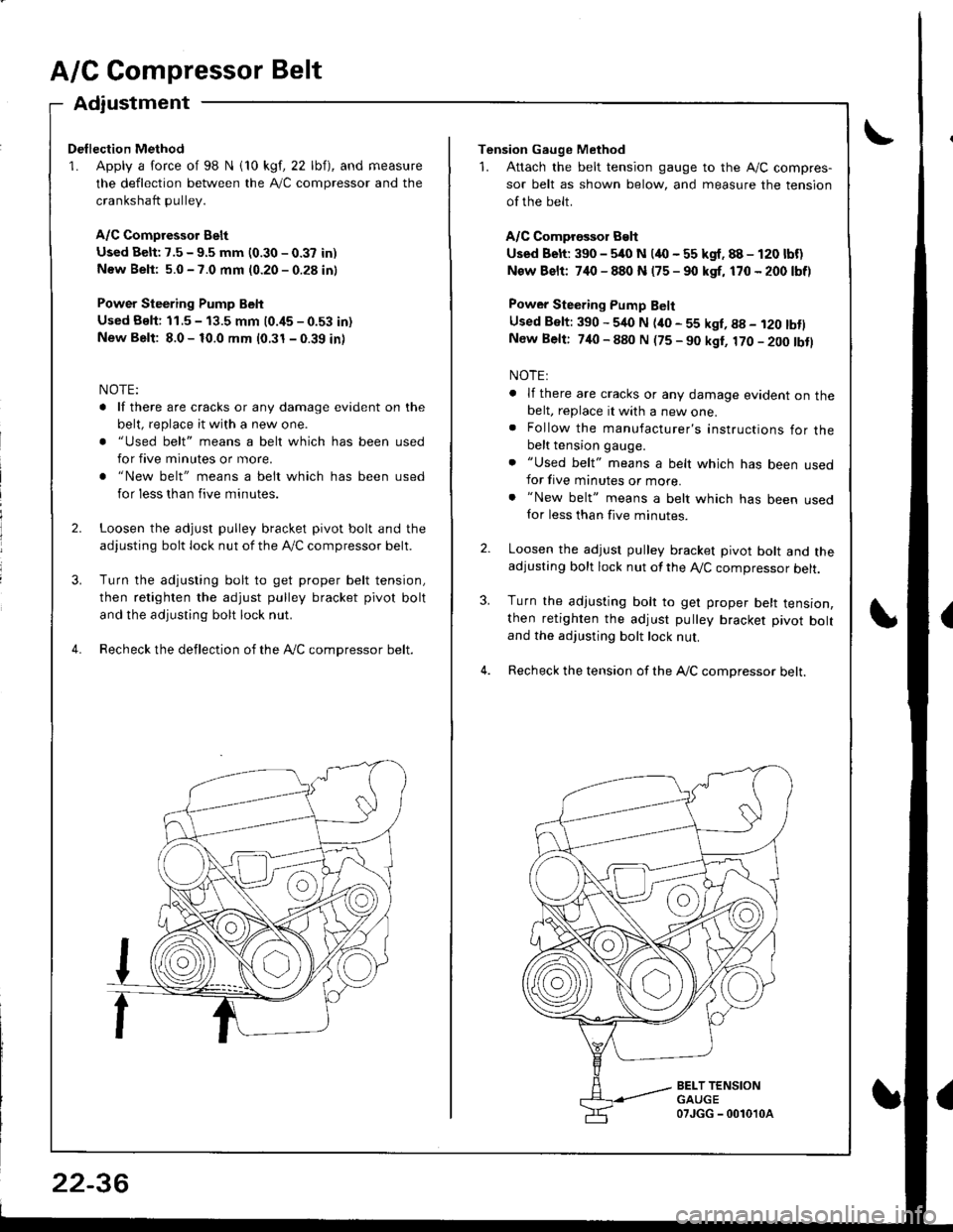
1. Apply a force of 98 N i10 kgf, 22 lbf), and measure
the deflection between the A,/C compressor and the
crankshaft pullev.
A/C Compressor Belt
Used Belt: 7.5 - 9.5 mm (0.30 - 0.37 in)
New Beli: 5.0 - 7.0 mm (0.20 - 0.28 in)
Power Steering Pump Belt
Used Bslt: 11.5 - 13.5 mm (0.i15 - 0.53 in)
New Belt: 8.0 - 10.0 mm (0.31 - 0.39 in)
NOTE:
. lf there are cracks or any damage evident on the
belt, replace it with a new one.
. "Used belt" means a belt which has been used
for five minutes or more.
. "New belt" means a belt which has been used
for less than five minutes.
Loosen the adjust pulley bracket pivot bolt and the
adjusting bolt lock nut of the lVC compressor belt.
Turn the adjusting bolt to get proper belt tension,
then retighten the adjust pulley bracket pivot bolt
and the adjusting bolt lock nut.
Recheck the deflection of the Ay'C compressor belt.
22-36
Tension Gauge Method
1. Attach the belt tension gauge to the Ay'C compres-
sor belt as shown below, and measure the tension
of the belt.
A/C Comprossor Belt
Used Belt: 390 - 5/rc N (4O - 55 kgf. 88 - 120 lbf)
New Bslt: 7,10 - 880 N (75 - 90 kgf, 170 - 200 lbf)
Power Steering Pump Belt
Used Belt: 390 - 540 N (ito - 55 kgl, g8 - i20 tbtlNew Belt: 740 - 880 N (75 - 90 kgt, 170 - 200 tbtl
NOTE:
. lf there are cracks or any damage evident on thebelt, replace it with a new one.. Follow the manufacturer's instructions for thebelt tension gauge.
. "Used belt" means a belt which has been usedfor five minutes or more.. "New belt" means a belt which has been usedfor less than five minutes.
Loosen the adjust pulley bracket pivot bolt and theadjusting bolt lock nut of the A,/C compressor belt.
Turn the adjusting bolt to get proper belt tension,then retighten the adjust pulley bracket pivot boltand the adjusting bolt lock nut.
Recheck the tension of the A,/C compressor belt.
3.
BELT TENSIONGAUGE07JGG - 0010'l0a