1998 HONDA INTEGRA low oil pressure
[x] Cancel search: low oil pressurePage 1491 of 1681

- How the Circuit Works
The low engine oil pressure indicator light works in
two ways: il flashes continuously following a
momentary loss of engine oil pressure, or it comes
on and stays on with a complete loss of engine oil
oressure,
When the engine first starts, before its oil pressure
rises above 4.3 psi, voltage is applied to the closed
and grounded engine oil pressure switch and the
light comes on to test the bulb.
With the engine running, voltage is applied at the
WHT/BLU wire of the integrated control unit. With
normal engine oil pressure, the engine oil pressure
switch is open and the low oil pressure indicator
light does not come on. lf the engine oil pressure
switch closes momentarily (more than 0.5 seconds)
but then opens again, the YEURED wire at the
integrated control unit will sense ground through the
switch. The integrated control unit will then provide
and remove ground for the low oil pressure indicator
light through the YEURED wire. The light will flash
on and off until you turn the ignition switch off. The
flashing feature will not work until 30 seconds after
initial voltage is applied to the WHT/BLU wire of the
oil pressure indrcator llasher circuit. This delay
keeps the low oil pressure indicator light from
coming on during engine warm-up.
lf engine oil pressure falls below 4.3 psi and does
not increase, the engine oil pressure switch will stay
closed. The low oil pressure indicator light will then
come on and stay on.
Refer to the Service Manual (Section 23, Electrical)
for specific tests or troubleshooting procedures.
72-1
Page 1632 of 1681

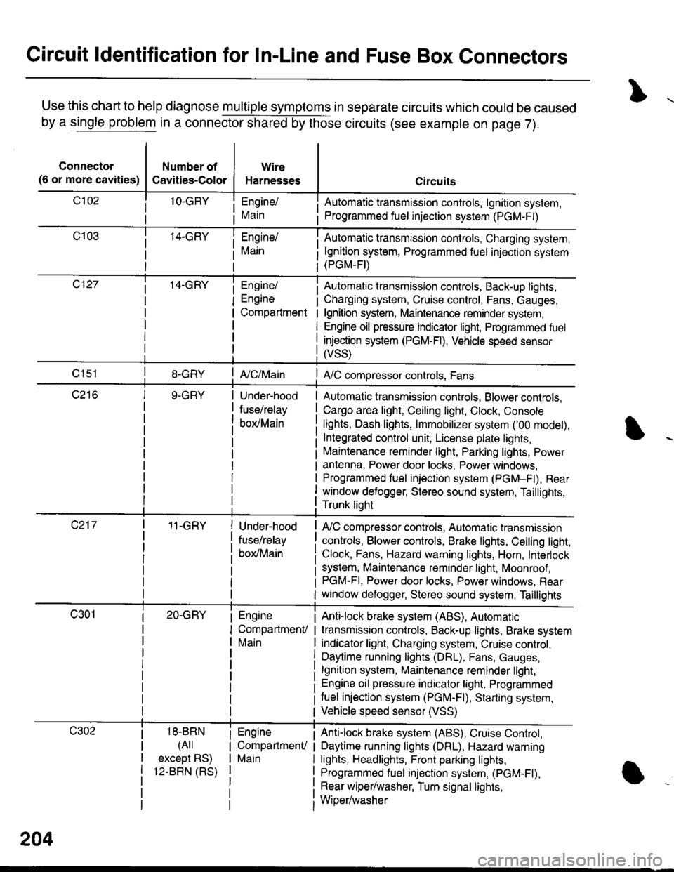
Circuit ldentification for In-Line and Fuse Box Connectors
Use this chart to help diagnose multiple symptoms in separate circuits which could be caused
by a single problem in a connector shared by those circuits (see example on page 7).
Connector
(6 or more cavities)
Number of
Cavities-Color
Wire
Harnesses
Engine/
Main
Engine/
Engine
Compartment
I Automatic transmission controls, lgnition system,
i Programmed fuel injection system (PGM-F|)
Automatic transmission controls, Charging system,
lgnition system, Programmed fuel injection system(PGM-FI)
Automatic transmission controls, Back-up lights,
Charging system, Cruise control, Fans, Gauges,
lgnition system, Maintenance reminder system,
Engine oil pressure indicator light, Programmed fuel
injection system (PGM-Fl), Vehicle speed sensor
ffss)
| {c/Main! A,/C compressor controls, Fans
Under-hood
fuse/relay
box/Main
Automatic transmission controls, Blower controls,
Cargo area light, Ceiling light, Clock, Console
lights, Dash lights, lmmobilizer system ('00 model),
Integrated control unit, License plate lights,
Maintenance reminder light, Parking lights, Power
antenna, Power door locks, Power windows,
Programmed fuel iniection system (PGM-Fl), Rear
window defogger, Stereo sound system, Taillights,
Trunk lioht
11-GRY
18-BBN
(4il
except BS)
12-BBN (RS)
Under-hood
fuse/relay
box/Main
Engine
CompartmenV
Main
Engine
CompartmenU
Main
lr,/C compressor controls, Automatic transmission
controls, Blower controls, Brake lights, Ceiling light,
Clock, Fans, Hazard warning lights, Horn, Interlock
system, Maintenance reminder light, Moonroof ,PGM-FI, Power door locks, Power windows, Rear
window defogger, Stereo sound system, Taillights
Anti-lock brake system (ABS), Automatic
transmission controls, Back-up lights, Brake system
indicator light, Charging system, Cruise control,
Daytime running lights (DRL), Fans, Gauges,
lgnition system, Maintenance reminder light,
Engine oil pressure indicator light, Programmed
tuel injection system (PGM-F|), Starting system,
Vehicle speed sensor (VSS)
Anti-lock brake system (ABS), Cruise Conkol,
Daytime running lights (DRL), Hazard warning
lights, Headlights, Front parking lights,
Programmed fuel injection system, (PGM-Fl),
Rear wiper/washer, Turn signal lights,
Wiper/washer
204
Page 1634 of 1681

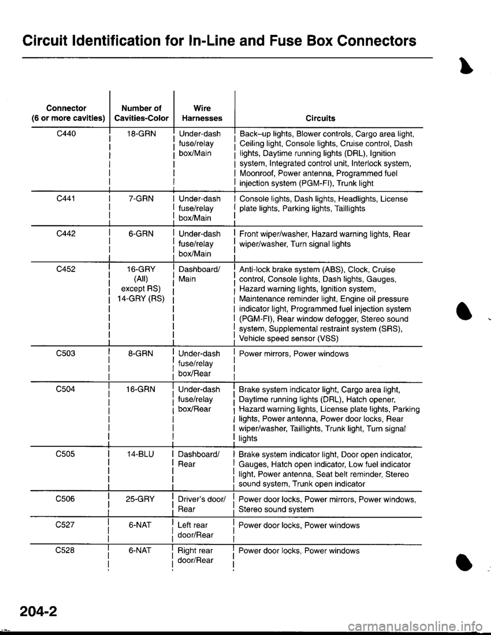
Circuit ldentification for In-Line and Fuse Box Gonnectors
Connector
(6 or more cavities)
Number of
Cavities-Color
18.GRN
Wire
Harnesses
Under-dash
fuse/relay
borMain
Circuits
Back-up lights, Blower controls, Cargo area light,
Ceiling light, Console lights, Cruise control, Dash
lights, Daytime running lights (DRL), lgnition
system, Integrated control unit, Interlock system,
Moonroof, Power antenna, Programmed fuel
injection system (PGM-Fl), Trunk light
7-GRNUnder-dash
fuse/relay
box/Main
Console lights, Dash lights, Headlights, License
plate lights, Parking lights, Taillights
c4426-GRN
16-GRY
(Ail)
except RS)
14-GRY (RS)
16-GRN
Under-dash
tuse/relay
box/Main
Dashboard/
Main
Under-dash
fuse/relay
box/Rear
Under-dash
fuse/relay
box/Rear
Front wiper/washer, Hazard warning lights, Rear
wiper/washer, Turn signal lights
Anti-lock brake system (ABS), Clock, Cruise
control, Console lights, Dash lights, Gauges,
Hazard warning lights, lgnition system,
Maintenance reminder light, Engine oil pressure
indicator light, Programmed fuel injection system
(PGM-Fl), Rear window defogger, Stereo sound
system, Supplemental restraint system (SRS),
Vehicle speed sensor (VSS)
Power mirrors, Power windows
Brake system indicator light, Cargo area light,
Daytime running lights (DRL), Hatch opener,
Hazard warning lights, License plate lights, Parking
lights, Power antenna, Power door locks, Rear
wiper/washer, Taillights, Trunk light, Turn signal
liohts
Dashboard/
Rear
Brake system indicator light, Door open indicator,
Gauges, Hatch open indicator, Low fuel indicator
light, Power antenna, Seat bell reminder, Stereo
sound system, Trunk open indicator
25-GRYDriver's door/
Rear
Left rear
door/Rear
Power door locks, Power mirrors, Power windows,
Stereo sound svstem
I Power door locks, Power windows
lJczat6-NATRight rear
door/Rear
I Power door locks, Power windowsI
a
204-2
Page 1641 of 1681

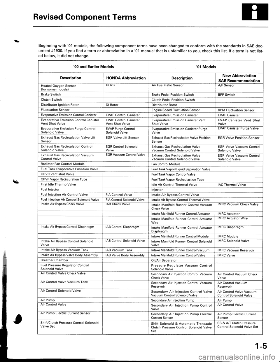
Revised Component Terms
\
\
Beginning with '01 models, the following component terms have been changed to conform with the standards in SAE doc-
ument J1930. lf you find a term or abbreviation in a '01 manual that is unfamiliar to you, check this list. lf a term is not list-
ed below, it did not chanqe.
'00 and Earlier Models'01 Models
DescriptionHONDA AbbreviationDescriptionNew Abbreviation
SAE Recommendation
Heated Oxygen Sensor(for some models)HO2SArr ruet llalto )ensorA,/F Sensor
Brake SwitchBrake Pedal Position SwitchBPP Switch
Clutch SwitchClutch Pedal Position Switch
Distributor lgnition RotorDl RotorDistributor Rotor
Fluctuation SensorEngine Speed Fluctuation SensorRPM Fluctuation Sensor
Evaporative Emission Control CanisterEVAP Control CanisterEvaDorative Emission CanisterEVAP Canister
Evaporative Emission Control CanisterVent Shut ValveEVAP Control CanisterVent Shut ValveEvaporative Emission Canister VentShut ValveEVAP Canister Vent ShutValve
Evaporative Emission Purge ControlSolenoid ValveEVAP Purge ControlSolenoid ValveEvaporative Emission Canister PurgeValveEVAP Uanister Purge Valve
Exhaust Gas Recirculation Valve LiftSensorEGR Valve Lift SensorExhaust Gas Recirculation Valve PositionSensorEGR Valve Position Sensor
Exhaust Gas Recirculation ControlSolenoid ValveEGR Control SolenoidValveExhaust Gas Recirculation ValveVacuum Control Solenoid ValveEGR Valve Vacuum ControlSolenoid Valve
Exhaust Gas Recirculation VacuumControl ValveEGR Vacuum Control ValveExhaust Gas Recirculation ValveVacuum Control Solenoid ValveEGR Valve Vacuum ControlSolenoid Valve
Radiator Fan Control ModuleFan Control Module
Fuel Tank Evaporative Emission ValveFuel Tank Vapor/Liquid Separation Valve
ORVR Vent shut ValveFuel Tank Vaoor Control Valve
ORVR Vaoor Recircuration TubeFuel Tank Vaoor Recirculastion Tube
First ldle Thermo Valveldle Air Control Thermal ValveIAC Thermal Valve
Fuel InjectorI njector
Fuel Iniection Air Control ValveFIA Control ValveIntake Air Bypass Control Valve
Fuel Injection Air Control Solenoid ValveFIA Control Solenoid ValveIntake Air Bypass Control Thermal Valvelntake Air BvDass Check ValveIAB Check ValveIntake Manifold Runner Control VacuumCheck ValveIMRC Vacuum Check Valve
Intake Manifold Runner Control ActuatorIMRC Actuator
Intake Manifold Runner Control ActuatorWireIMRC Actuator Wire
ntake Air Bypass Control DiaphragmIAB Control DiaphragmIntake Manifold Runner control ActuatorDiaphragmilvrr1u urapnragm
Intake Manifold Runner Control ModuleIMRC Module
Intake Air Bypass Control SolenoidValvelAts Control Solenoid ValveIntake Manifold Runner Control SolenoidValveIMRC Solenoid Valve
Intake Air Bvpass Vacuum TankIAB Vacuum TankIntake Manifold Runner Control VacuumIMRC Vacuum Reservoir
Intake Air Bypass Valve Body AssemblyIAB Valve Body AssemblVIntake Manifold Runner Control ValveIMRC Valve
Breather ChamberOil/Air Separator
Fuel Pressure Regulator ControlSolenoid ValvePressure Regulator Vacuum ControlSolenoid ValveAir Control Valve Check ValveSecondary Air In.jection Control VacuumCheck ValveAir Control Vacuum CheckValveArr Control Valve Vacuum TankSecondary Air Injection Control VacuumReservoirAir Control VacuumReservoirAir Control Solenoid ValveSecondary Air Injection Control ValveVacuum Control Solenoid ValveAir Control Valve VacuumControl Solenoid Valve
Air PumpSecondary Air Injection PumpAir PumpAir Control ValveSecondary Air Injection Pump ControlValveAir Control Valve
Arr rump tsreclnc uurrent bensorSecondary Air Injection Pump ElectricCurrent SensorAir Pump Electric CurrenlSensor
Shift/Clutch Pressure Control SolenoidValve SetShift Solenoid & Automatic TransaxleClutch Pressure Control Solenoid ValveSet
SS & A,/T Clutch PressureControl Solenoid Valve Set
1-5