1998 HONDA INTEGRA ad blue
[x] Cancel search: ad bluePage 91 of 1681

\
Valve Seats
Reconditioning
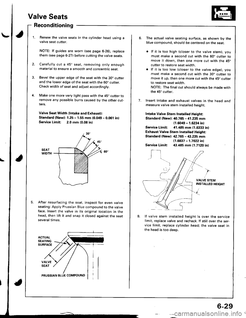
ACTUALSEATINGSURFACE
VALVESEAT
Renew the valve seats in the cylinder head using avalve seat cutter.
NOTE: lf guides are worn (see page 6-26), replace
them {see page 6-27) before cutting the valve seats.
Carefully cut a 45" seat, removing only enoughmaterial to ensure a smooth and concentric seat.
Bevel the upper edge of the seat with the 30. cutterand the lower edge of the seat with the 60. cutter.Check width of seat and adjust accordingly.
Make one more very light pass with the 45o cutter toremove any possible burrs caused by the other cut-rers.
V8lv6 S€at Width (lntake and Exhaustl:
Standard {New}: 1.25 - 1.55 mm {0.0/t{, - 0.061 in}
S€rvice Limit: 2.0 mm 10.08 in)
After resurfacing the seat, inspect for even valveseating: Apply Prussian Blue compound to the valveface. Insert the valve in its original location in thehead, then lift it and snap it closed against the seatseveral times.
PRUSSIAN BLUE COMPOUNO
6-29
o.The actual valve seating surface, as shown by theblue compound, should be centered on the seat.
lf it is too high (closer to the valve stem), you
must make a second cut with the 60" cutter tomove it down, then one more cut with the 45"
cutter to restore seat width.
lf it is too low (closer to the valve edge), you
must make a second cut with the 30. cutter tomove at up, then one more cut with the 45. cutterto restore seat width.
NOTE: The final cut should always be made with
the 45" cutter.
Insert intake and exhaust valves in the head andmeasure valve stem installed height.
Intake Valve Stem Inst8lled Height:
Standard lN6wl: 40.765 - i11.235 mm(1.6049 - 1.6234 in)
Servico Limiti i01.,|85 mm (1.6333 in)
Exhaust Valv€ Stem Installed Height:
Standard {Newl: ,[2.765 - 4:1.235 mm
1.
{1.68i}7 - 1.7022 inl,(1.485 mm 11.7120 inlService Limit:
I_1I
VALVE STEMINSTAI-LED HEIGHT
8.lf valve stem installed height is over the servicelimit, replace valve and recheck. lf still over the ser-vice limit, replace cylinder head; the valve seat in
the head is too deep.
Page 153 of 1681

I
IConnecting Rod Bearings
Clearance
1. Remove the connecting rod cap and bearing half.2. Clean the crankshaft rod journal and bearing halfwith a clean shop towel.
3. Place the plastigage across the rod journal.
4. Reinstall the bearing half and cap, and torque thenuts (818C5 engine: see page 7-19).
81881 engine:31 N.m (3.2 kgnm,23 tbf.ftl
Bl8Cl engine:44 N.m (4.5 kgl.m.33 tbl.ft)
NOTE: Do not rotate the crankshaft during inspection.
Connecting Rod Bearing-to-Journal Oil Clearance:81881 engine:
Standard {Newl: 0.020 - 0.038 mm
{0.0008 - 0.0015 inl
Service Limit: 0.050 mm {0.0020 inl
818C1 engine:
Standald {Newl: 0.032 - 0.050 mm
10.0013 - 0.0020 in)
Service Limit: 0.060 mm {0.0024 in}
B18C5 engine:
Standard lNew): 0.038 - 0.050 mm(0.0015 - 0.0020 inl
Service Limit: 0.060 mm t0.0024 inl
lf the plastigage measures too wjde or too narrow,remove the upper half of the bearjng, install a new,complete bearing with the same color code (select
the color as shown in the rig ht column), andrecheck the clearance.
CAUTION: Do not file, shim, or scrape the bearingor the caps to adiust clearance.
It the plastigage shows the clearance is still incorrect,try the next larger or smaller bearing (the color listedabove or below that one), and check clearance again.
NOTEr It the proper clearance cannot be obtainedby using the appropriate larger or smaller bearings,replace the crankshaft and stan over.
Selection
CAUTION: lf the codes are indecipherable because ofan accumulation of dirt and dust, do not scrub themwith a wire brush or scraper. Clean them only with sol-vent or delergent.
Connecting Rod Code Location
A number has been stamped on the side of each con-necting rod as a code for the size of the big end. Use it,and the letters stamped on the crank lcodes for rod iour-nal size), to choose the correct bearinqs.
Connecting Rod Journal Code Loc.tions {Letters or Bers)
Beering ldentification
23
Y"rl.:_,
Gie& ,
!**
i:1"
BlackBlue
Color code ison the edge oIthe bearing.Larger big end bore
Smaller bearing (th rche.)
lHll
I F;;lll
lL".;|l
Smaller Smallerrod bearing
iournal (thicker)
Half ot number isstamped on bearingcap and the otherhalf is stamped onrod.
PLASTIGAGE STRIP
Page 154 of 1681

Connecting Rod BearingsCrankshaft
Selection (cont'dlRemoval
818C5 engine:
CAUTION: lf the codes are indecipherable because of
an accumulation of dirt and dust, do not scrub them
with a wire brush or scraper. Clean them only with sol-
vent or detergent.
Connecting Rod Code Location
A number has been stamped on the side of each con-
necting rod as a code for the size of the big end. Use it,
and the letters stamped on the crank lcodes for rod jour-
nal size), to choose the correct bearings.
ilb
Color code ison the edge ofthe bearing.Larger big end bore
Smaller bearing (thicker)
Smallerbeal|ng(thicked
1rI
llli
tl
ilI
I
*z-t o
Smallerrodjournal
Connecting Rod Journal Code Locations {Letters or Barsl
Beering ldentitication
NOTE: End play for the connecting rods and crankshaft
should be inspected before removing the crankshaft.
1. Remove the oil pan, oil screen and the oil pump.
GASKETReplace.
Remove the baffle plate.
Turn the crankshaft so No.2 and 3 crankpins are at
the bottom.
Remove the right side cover.
OIL PAN
Half of number isstamped on bearingcap and the otherhalf is stamped onrod.
212223242526
T
z
Black
Black
Blue
Page 595 of 1681

Throttle Control Cable
Inspection
NOTE: Before inspecting the throttle controlcable, makesure:
a Throttle cable tree play is correct (see section I 1).a ldle speed is correct (see section 1l).a To warm up the engine to normal operating tempera-
ture (the cooling fan comes on).
1 . Verify that the throttle control cable is clamped cor-rectly in three positions.
CONTROL CABLE
LOWERHOSEClamp at the end ofblue tape on the cable.
Verily that the throttle controldrum is synchronized
with the throttle linkage while depressing and releas-
ing the accelerator pedal.
ll the throttle control drum is not synchronized with
the throttle linkage, adjust rhe throttle control cable.
(cont'd)
14-179
Page 597 of 1681

Adjustment
NOTE: Before adjusting the throttle controlcable, make
sure:
a Throttle cable lree play is correct (see section 11).a ldle speed is correct (see section 11).a To warm up the engine to normal operating tempera-
ture {the cooling fan comes on)
1 . Verify that the throttle control cable is clamped correctly in three positions.
THROTTLEATF COOLERPIPE
LOWERHOSEClamp at the end ofblue tape on the cable.
Verily that the throttle linkage is in the fully-closedposttron.
Loosen the locknut of the throttle control cable at
the throttle linkage.
CONTROL CABLE
LOCKNUTS
14-181
Push in this directron.
Remove the free play of the throttle control cable
with the locknut, while pushing the throttle control
drum to the tull-closed potision as shown.
5. Tighten the locknuts.
6.After tightening the locknuts, inspect the synchroni-
zation and throttle control drum movement.
Page 868 of 1681

Windshield, Rear Window, Ouarter Glass
lndex
part names show the quantities of the parts Lrsed.
UPPER MOLDINGUPPER RUBBER DAM
CLIP E, 2 White
CLIP F, 2 Lett. WhiteBight. Blue
CLIP A, 8 Red
c
f(
RETAINER, 6 Orange
CLIP B, 2 Orange
CLIP C, 2 Black
LEFT SIDE MOLDING
CLIP D, 2 Green
AINER, 2 Yellow
WINOSHIELDRemoval, page 20,55Installation, page 20 56
REAR
GLASS BRACKET, 2
,^
,r"
A
RET
a
REAR WINDOW MOLDING
UPPER FASTENER, 2(Self-adhesive-type, glass side)
UPPER FASTENER,2(Self adhesive_type, hatch side)
SIDE RUBBERDAM, 2
OUARTER GLASSRemoval, Page 20-73
SPACER,2 Installation, Page 20-73
TAPE B, 2ADHESIVE
/
Ar-/
I
BUSHING SEAL.2
Removal, page 20-61Installation, page 20-62
NOTE: The numbers after the
Hatchback
RIGHT SIDE MOLDING
'l
@q
a
e,
Page 874 of 1681

13. Pack adhesive into the cartridge without air pock-
ets to ensure continuous deliverv. Put the cartridge
in a caulking gun, and run a bead of adhesive around
the edge of the windshield as shown.
NOTEr Apply the adhesive within 30 minutes after
applying the glass primer.
12 mm 10.47 in)T-/
l 1l , ronesrvr
8 mm 10.31 in)
bead at each
'a\
'..\
\...
Make a slightly thickerMOLDING
LOWERBUBBEB
2mm
10.07 in)
DAM
WINDSIIIELD
14. Use suction cups to hold the windshield over the
opening, align it with the alignment marks made in
step 7, and set it down on the adhesive. Lightly push
on the windshield until its edge is tully seated on the
adhesive all the way around.
NOTE: Do not close or open the doors until adhe-
sive is dry.
SUCTIONCUPS ALIGNMENT MABK
t
ADHESIVE
'15. Install the clips on
> i Clip locations
A> : Clip A, a
both side moldings.
B<: Clip B, 2
_)_)
C<: Clip C lHatchback, 2llSedan,4l
D<: Clip D (Hatchback, 2lEV; Clip E, 2
\Yr i
P/l
Y___/
F<: Clip F, 2 |
_)
F:
F (Left. Whitel(Right. Blue)E (Whilel
I
A lRed)
A (Redl
stoEMOLDINGA (Red)/B (Hatchback, Orange)
{Sedan, Brownl
A lRedJ
I
\c (Hatchbsck. Elackllsedan, orange)
O {Hatchback, Green)C {sedan, Orange)
Scrape or wipe the excess adhesive of{ with a put
ty knite or towel.
NOTE: To remove adhesive from a painted surface
or the windshield, wipe with a soft shop towel damp
ened with alcohol.
{cont'd)
20-59
Page 1063 of 1681

Troubleshooting
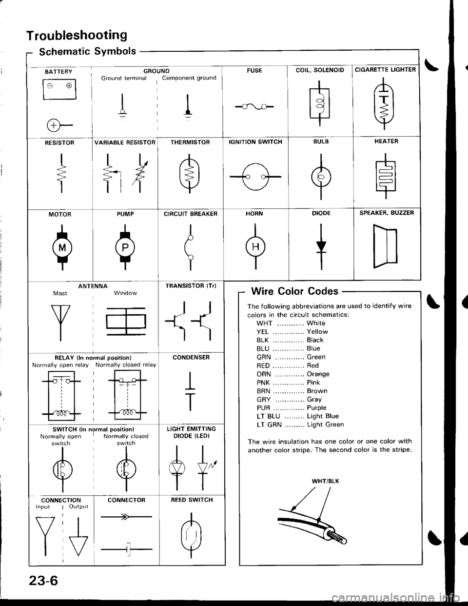
Schematic Symbolsym
BATTEBY
tr3
o-
GROUNDGround terminal Componenr ground
I il
FUSE
rhtdl
l9l.|
CIGARETTE LIGHTER
,A
lrl
Y
RESISTOR
+
T
VARIABLE RESISTOR
TD
=rX
ttf
THERMISTOR
/b'
t=l
v
IGNITION SWITCH
1-\-T- l.--
BULB
A
Y
HEATER
-h
t=l
tr
MOTOR
0
PUMP
A
Y
CIRCUIT EREAKER
I
t
Y
HORN
+
DIODE
+
SPEAKER, BUZZER
D
Mast
Y
ANTtiNNA
T,
TRANSISTOR (Tr)
ll
+1^'l
)
Wire Color Codes
The following abbreviations are used to identify wire
colors in the circuit schematics:
WHT ............ White
YE1 .............. Yellow
81K .............. Black
B1U .............. Blue
GRN ............. Green
RED .............. Red
ORN ............. Orange
PNK .............. Pink
BRN .............. Brown
GRY ............. Gray
PUR .............. Purple
LT BLU ......... Light Blue
LT GRN ......... Light Green
The wire insulation has one color or one color with
another color stripe.'The second color is the stripe.
WHT/BLK
,//,aI,//t- /
R
BELAY lln noNormally open relayrmal position)
Normally closed relay
-tr-f,-
l=T= |
til
trf
CONDENSER
I
T
SWITCH {ln nrNormally openswitch
I
/6\
v
I
)rmal position)Normally closed
I
A
w
I
LIGHT EMITTINGDIODE (LEDI
AJ"
YT
CONNE
V
I
CTIONOutput
J,
CONNECTOR
+>-
l-l'l
REED SWITCH
.K
Irr ]
Y