Page 1244 of 1681
Back-up Lights
Circuit Diagram
IGNITIONswlTcHUNOER.HOOD FUSEi RELAY BOX
EACK.UPLIGHTswtTcH/ / on lhe \r I ransnBgon I
GRN/BLK
IIJ
TRAILERL]GHT NGCONNECTOR
GRN/BLK
IzA arcx.upI P ' LIGHTS
f
r:zce'21
IBLK
II
I
G503
YEL
I
SnoriARr*r.r r*i(3;f;iil're' )V(oN h posirion [E )
l"
IGRN/BLK
23-147
)
I
Page 1245 of 1681
Back-up Lights
Test
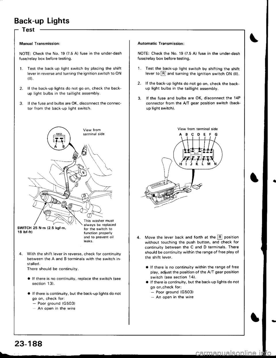
Manual Transmission:
NOTE: Check the No. 19 (7.5 A) fuse in the underdash
fuse/relay box before testing.
Test the back-up light switch by placing the shift
lever in reverse and turning the ignition switch to ON
fl r).
lI the back-up lights do not go on, check the back-
up light bulbs in the taillight assembly.
lI the fuse and bulbs are oK, disconnect the connec-
tor from the back-up light switch.
2.
3.
l.
SWITCH 25 N.m (2.5 kgf-m,'18 lbf-Ir)
This washer mustalways be replacedfor the switch totunction properly
and 10 prevent oilteaKs,
terminal side
4. With the shift lever in reverse, check for continuity
between the A and B terminals with the switch in-
stalled.
There should be continuity.
a It there is no continuity, replace the switch (see
section 13).
a lf there is continuity, but the back-up lights do not
go on, check for:- Poor ground {G503}
An open in the wire
A
6
Automatic T.ansmission:
NOTE: Check the No. 19 (7.5 A) fuse in the under-dash
fuse/relay box before testing.
2.
'1 .Test the back-up light swirch by shifting the shiftlever to @ and turning the ignition switch ON (ll).
lf the back-up lights do not go on, check the back-
up light bulbs in the taillight assembly.
lf the fuse and bulbs are OK, disconnect the 14P
connector from the A,/T gear position switch (back-
up light switch).
View from terminal side
ABCDEFG
Move the lever back and torth at the E position
without touching the push button, and check for
continuity between the C and D terminals. There
should be continuity within the range of free play of
the shilt lever.
a lf there is no continuity within the range of free
play, adiusl the position ot the A/T gear position
switch {see section 14}.
a lf there is continuity, but the back-up lights do not
go on,check tor:- Poor ground {G5O3)- An open in the wire
Page 1259 of 1681
3.
1.
wel
Remove the quarter trim panel (Hatchback) or trunk
side trim panel {Sedan).
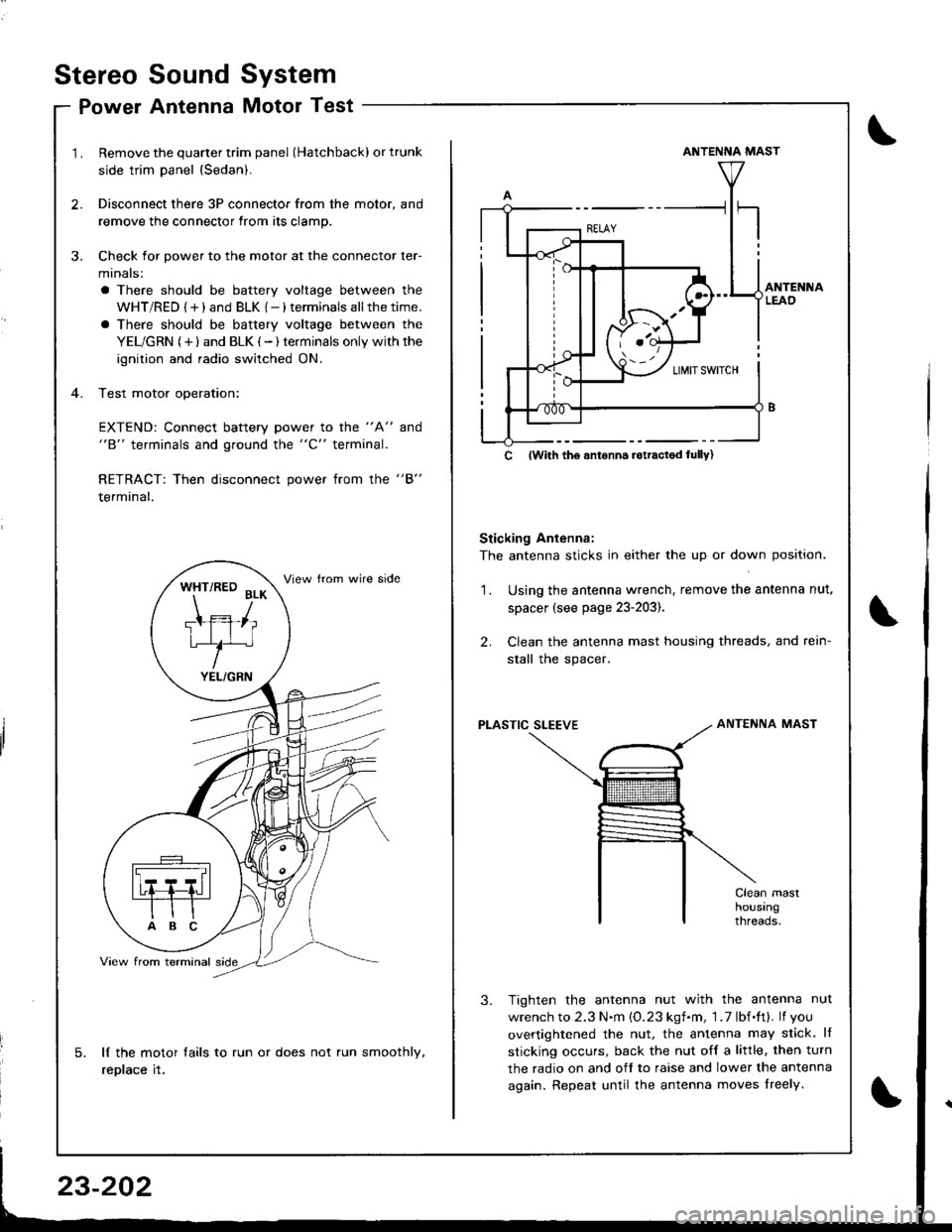
Disconnect there 3P connector from the motor, and
remove the connector from its clamp.
Check for power to the motor at the connector ler-
minals:
a There should be battery voltage between the
WHT/RED {+) and BLK {-) terminals allthetime.
a There should be battery voltage between the
YEL/GRN (+) and BLK (-) terminals only withthe
ignition and radio switched ON.
Test motor operation:
EXTEND: Connect battery power to the "A" and"B" terminals and ground the "C" terminal.
RETRACT: Then disconnect power from the "B"
terminal.
lf the motor lails to run or does not run smoothly,
replace it.
WHT/RED BLK
Ttffiliu/^
YEL/GRN
ANTENNA MAST
Sticking Antenna:
The antenna sticks in either the up or down position.
Using the antenna wrench, remove the antenna nut.
spacer (see page 23-203).
Clean the antenna mast housing threads, and rein-
stall the spacer.
2.
1.
PLASTIC SLEEVEANTENNA MAST
Tighten the antenna nut with the antenna nut
wrench to 2.3 N.m {O.23 kgf.m, 1 .7 lbf.ft}. lf you
overtightened the nut, the antenna may slick. lf
sticking occurs, back the nut off a little, then turn
the radio on and off to raise and lower the antenna
again. Repeat until the antenna moves lreely.
c lwith tho anronn6 rotractod lully)
Stereo
Po
Sound
Antenna
System
Motor Test
\
Page 1267 of 1681
Horn
Switch Test (cont'd)
Remove the driver's airbag assembly (refer to the
SRS sub-section in section 23).
Check for continuity between the No. 2 terminal of
the cable reel sub-harness 3P connector and horn
Dositive terminal.
lf there is no continuity. replace the cable reel.
lf there is continuity, replace the horn switch.
a
a
HORN POSITIVE TERMINAL
23-210
9.
10.
11.
12.
lf all tests prove OK, reinstall the driver's airbag
assembly (re{er to the SRS sub-section in section 23).
Reconnect the driver's airbag connectors, and rein-
stall the access panel on the steering wheel.
Reconnect the front passenger's airbag connector,
and reinstall the glove box.
Connect the battery positive cable, then connect the
negative cable.
Atter installing the airbag assembly, confirm that
- the SRS indicator light should come on for about
six seconds and then go off with the ignition switch
oN 0t).- the horn sounds with the horn button pressed.
Page 1271 of 1681
Rear Window Defogger
Component Location Index
Description
The rear window de{ogger is controlled by the integrated control unit. Pushing the detogger switch in the Instrumentpanel sends a signal to the defogger timer in the integrated control unit, and the defogger stays on for 25 minutes oruntil the ignition switch is turned off. The indicator light in the switch comes on when the defogger works.
UNDER.OASH FUSE/RELAY BOX
r-'luijij u lNEAR WINDOWDEFOGGER SWITCHRemoval, page 23-217Test, page 23 217
REARDEFOGGERREI-AYTest, page 23-69
23-214
Page 1275 of 1681
Rear Window Defogger
Function TestDefogger Wires Repair
I
I
CAUTION: Be caretul not to scratch or damage the
defogger wires with the tester probe,
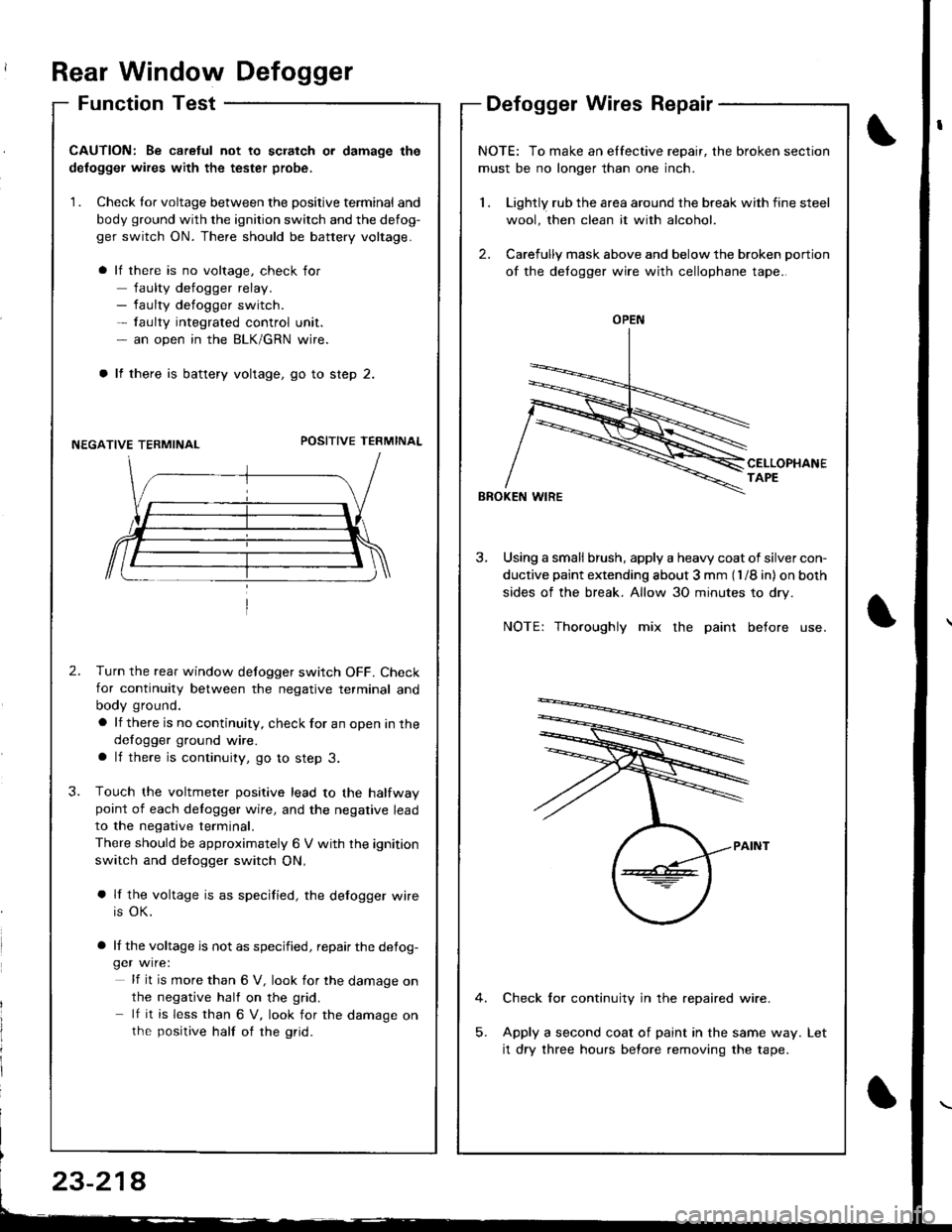
1. Check tor voltage between the positive terminal and
body ground with the ignition switch and the defog-
ger switch ON. There should be battery voltage.
lf there is no voltage, check for
faulty defogger relay.- faulty defogger switch.- faulty integrated control unit.- an open in the BLK/GRN wire.
lf there is battery voltage, go to step 2.
NEGATIVE TERMINALPOSITIVE TEFMINAL
2.Turn the rear window defogger switch OFF. Check
for continuity between the negative terminal and
body ground.
a lf there is no continuity, check for an open in the
defogger ground wire.a lf there is continuity, go to step 3.
Touch the voltmeter positive lead to the halfwaypoint of each delogger wire, and the negative lead
to the negative terminal.
There should be approximately 6 V with the ignition
switch and defogger switch ON,
a lf the voltage is as specified, the defogger wire
is OK.
a lf the voltage is not as specified, repair the defog-ger wire:
lf it is more than 6 V, look for the damage on
the negative half on the grid.
lf it is less than 6 V, look for the damage onthe positive half of rhe grid.
3.
NOTE: To make an elfective repair, the broken section
must be no longer than one inch.
1 . Lightly rub the area around the break with fine steel
wool, then clean it with alcohol.
2. Carefully mask above and below the broken portion
of the defogger wire with cellophane tape.
CELLOPHANETAPE
BBOKEN WIRE
3, Using a small brush, apply a heavy coat of silver con-
ductive paint extending about 3 mm (l /8 in) on both
sides of the break. Allow 30 minutes to dry.
NOTE: Thoroughly mix the paint before use.
Check for continuity in the repaired wire.
Apply a second coat of paint in the same way.
it dry three hours before removing the tape.
Let
OPEN
23-214
Page 1279 of 1681
Moonroof
Function Test
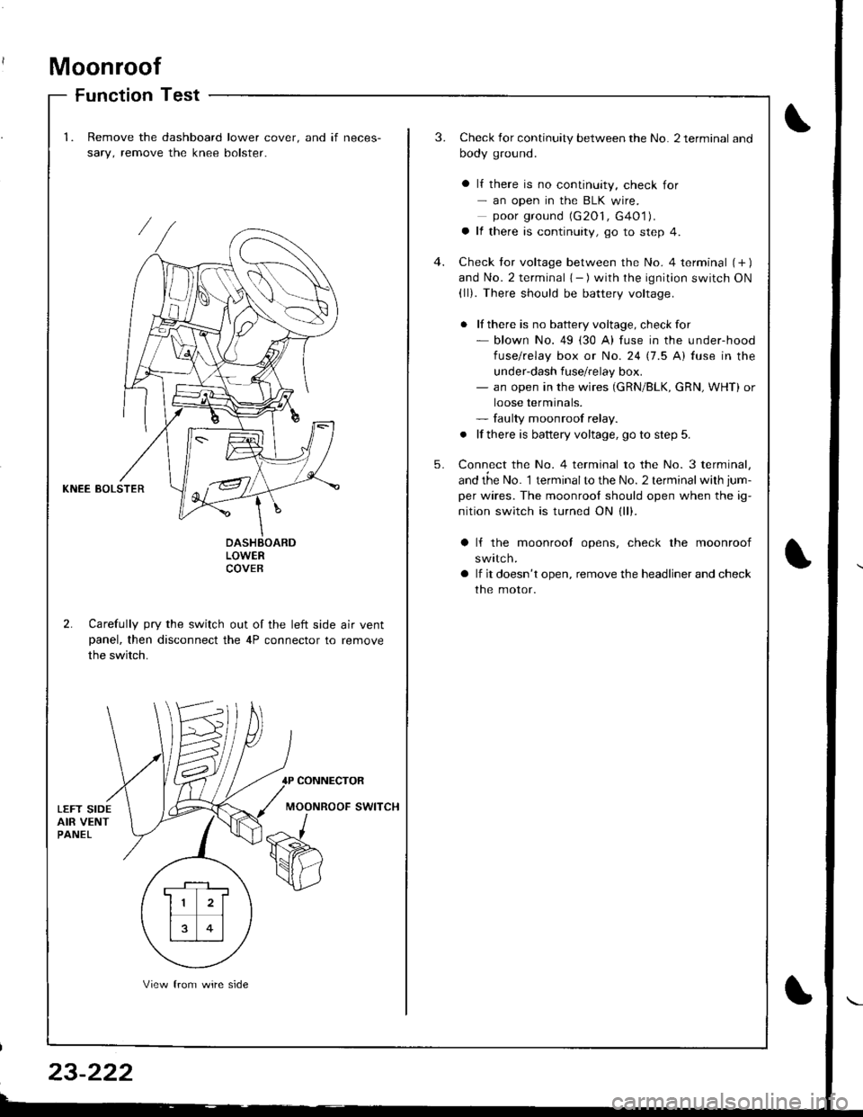
1.Remove the dashboard lower cover. and if neces-
sary, remove the knee bolster.
3.Check for continuity between the No. 2 terminal and
body ground.
a lf there is no continuity, check for- an open in the BLK wire.poor ground (G2O1, G4O1).a lf there is continuity, go to step 4.
Check tor voltage between the No. 4 terminal (+ )and No. 2 terminal { - ) with the ignition switch ON(ll). There should be battery voltage.
. lf there is no battery voltage, checkfor- blown No. 49 (30 A) fuse in the under-hood
fuse/relay box or No. 24 17.5 Al fuse in the
under-dash fuse/relay box.- an open in the wires (GRN/BLK, cRN, WHT) or
loose terminals.- faulty moonroof relay.
. lf there is battery voltage, go to step 5.
Connect the No. 4 terminal to the No. 3 terminal,
and the No. 1 terminalto the No. 2 terminal with jum-
per wires. The moonrool should open when the ig-
nition switch is turned ON (ll).
4.
5.
KNEE BOLSTER
LOWERCOVEB
2. Carefully pry the switch out of the left side air ventpanel, then disconnect the 4P connector to remove
the switch.
lf the moonrool opens, check the moonroof
swttcn.
lf it doesn't open, remove the headliner and check
the motor.
CONNECTOR
MOONROOF SWITCH
. F-_1 ,
11 2l
rt�1
13 0l
View from wire side
Page 1284 of 1681
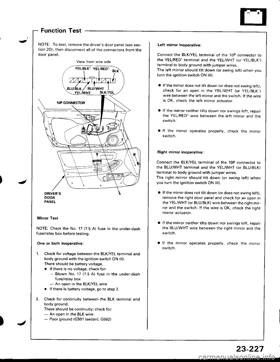
)
Function Test
NOTE: To test, remove the driver's door panel (see sec-
tion 20), then disconnect all of the connectors from the
ooor panet.
Mifior Test
NOTE: Check the No. 17 {7.5 A) fuse in the under-dashfuse/relay box before testing.
One or both inoperative:
Check for voltage between the BLK//EL terminal and
body ground with the ignition switch ON {ll).There should be battery voltage.
. lf there is no voltage, check for:* Blown No. 17 (7.5 A) fuse in the under-dash
fuse/relay box- An open in the BLK/YEL wire
. lf there is battery voltage, go to step 2.
Check for continuity between the BLK terminal and
body ground.
There should be continuity; check for.* An open in the BLK wire- Poor ground (G501 (sedan), G502)
vrllBtxt YEL/RED' aa*\
Left miror inoperative:
Connect the BLK,^/EL terminal of the 1OP connector to
the YEVRED1terminal and the YEL /VHT (or YEL/BLK1)
terminal to body ground with iumper wires.
The left mirror should tilt down (or swing left) when you
turn the ignition switch ON (ll).
a lf the mirror does not tilt down (or does not swing lett).check for an open in the YEL/WHT {or YEL/BLKr}wire between the left mirror and the switch. lf the wireis OK, check the lett mirror actuaror.
a lf the mirror neither tilts down nor swings left, repair
the YEL/REDr wire between the letr mirror and theswtlcn.
a lf the mirror operates properly, check the mirror
swttcn.
Right mirrol inoperative:
Connect the BLK/YEL terminal of the 10P connector to
the BLU,^/VHT terminal and the YELMHT {or BLU/BLK)
terminal to body ground with jumper wires.
The right mirror should tilt down (or swing left) whenyou turn the ignition switch ON (ll).
a lf the mirror does not tilt down (or does not swing left),
remove the right door panel and check for an open in
the YEL/WHT (or BLU/BLK) wire between the right mir-
ror and the switch. lf the wire is OK, check the right
mirror actuator.
a lf the mirror neither tilts down nor swings lett, repair
the BLU/WHT wire between the right mirror and the
swrtch.
a lf the mirror operates properly, check the mirror
switch.
23-227