Page 1191 of 1681
Engine Coolant Temperature (ECT) Gauge
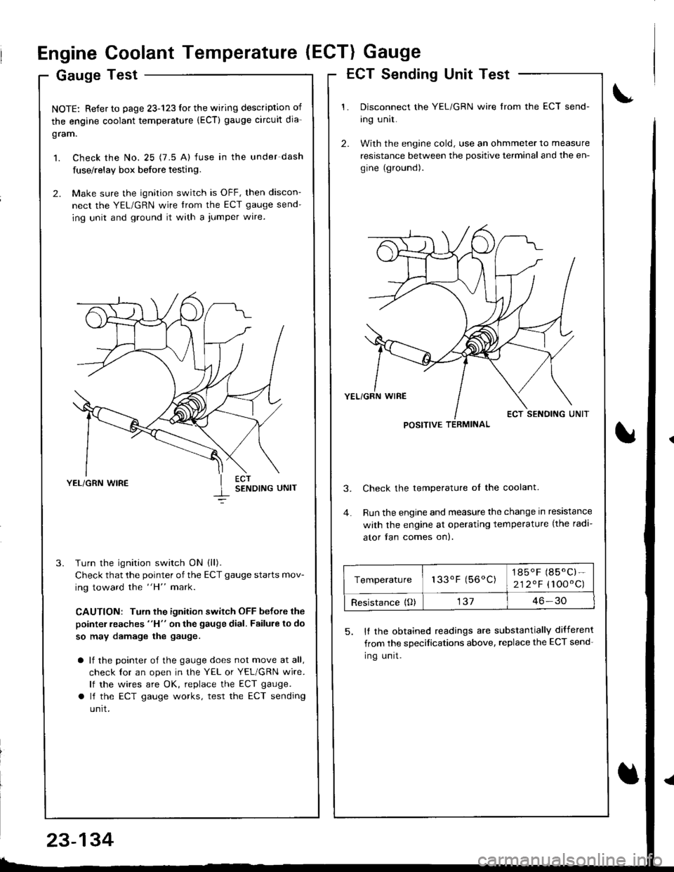
Gauge Test
NOTE: Refer to page 23-123 for the wiring description of
the engine coolant temperature (ECT) gauge circuit dia-
gram.
1. Check the No. 25 (7.5 A) fuse in the under-dash
fuse/relay box before testing.
2. Make sure the ignition switch is OFF, then discon-
nect the YEL/GRN wire trom the ECT gauge send-
ing unit and ground it with a jumper wire.
YEL/GRN WIRESENDING UNIT
Turn the ignition switch ON (ll).
Check that the pointer of the ECT gauge starts mov-
ing toward the "H" mark.
CAUTION: Turn the ignition switch OFF before the
pointer reaches "H" on the gauge dial. Failure to do
so may damage the gauge.
a lf the pointer of the gauge does not move at all,
check lor an open in the YEL or YEL/GRN wire.
lf the wires are OK, replace the ECT gauge.
a lf the ECT gauge works, test the ECT sending
unrt.
ECT Sending Unit Test
Disconnect the YEL/GRN wire from the ECT send-
ing unit.
With the engine cold, use an ohmmeter to measure
resistance between the positive terminal and the en-
gine (ground).
Check the temperature ol the coolant.
Run the engine and measure the change in resistance
with the engine at operating temperature (the radi-
ator fan comes on).
5. It the obtained readings are substantially different
from the sDecifications above, replace the ECT send-
Ing unrt.
POSITIVE TERMINAL
Temperature133oF (56oC)1850F (85.C)-
212.F (100'C)
Resistance {O)13746-30
23-134
Page 1194 of 1681
t
{)
)
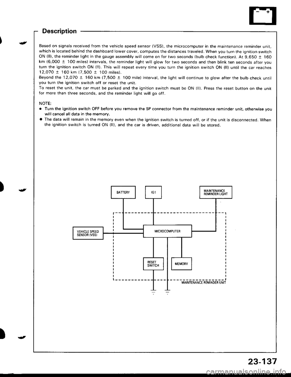
Based on signals received from the vehicle speed sensor (VSS). the microcomputer in the maintenance reminder unit,which is located behind the dashboard lower cover, computes the distances traveled. When you turn the ignition switchON (ll), the reminder light in the gauge assembly will come on for two seconds (bulb check tunction). At 9,650 1 160km {6,000 1 1O0 miles} intervals, the reminder light will glow for two seconds and then blink ten seconds after you
turn the ignition switch ON (ll). This will repeat every rime you turn the ignition switch ON {ll) until rhe car reaches12,O7O ! 1 60 km (7,500 t 100 miles).
Beyond the 12.o1O ! 160 km (7,5OO t IOO mile) interval, the light will continue to glow after the bulb check untilyou turn the ignition switch otf or reset the unit.
To reset the unit, the car must be parked and the ignition switch must be ON (ll). Press the reset button on the unitfor more than three seconds, and the reminder light will go off.
NOTE:
. Turn the ignition switch OFF before you remove the 5P connector from the maintenance reminder unit, otherwise vouwiil cancel all data in the memory.
a The data will remain in the memory even when the ignition switch is turned off, or if the unit is disconnected. Whenthe ignition switch is turned ON (lll, and the car is driven, additional data will be stored.
{
23-137
Page 1200 of 1681
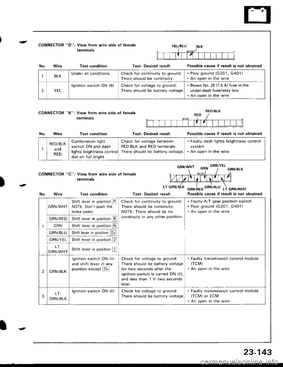
{CONNECTOR "D": View from wire side of lemale
terminalsYEL/BLU
CONNECTOR "8": View from wire side ot female
terminals
No.Wire
No.Wire
Test condition
Test condition
Test condition
Test: Desired result
Test: Desired result
Possible cause il result is not obtained
Possible cause if result is not obtained
Possible cause iI lesult is not obtained
)
CONNECTOR "C": View from wile side ot female
terminals
LT
No.Test: Desired result
1BLKUnderall conditionsCheck {or continuity to ground:
There should be continuity.
Poor ground (G201 , G401)
An open in the wire
2YEL
lgnition switch ON (ll)Check for voltage to groundl
There should be battery voltage
Blown No. 25 (7.5 A) fuse in the
under-dash fuse/relay box
An open in the wire
RED/BLK
1
R E D/BLK
ano
RED
Combination light
switch ON and dash
lights brightness control
dial on full bright
Check for voltage between
RED/BLK and RED terminalsl
There should be battery voltage.
. Faulty dash lights brightness control
system. An open in the wire
1
GRN/WHT
Shifl lever in position @NOTE: Don't push the
brake pedal.
Check {or continuity to ground:
There should be continuity.
NOTE: There should be no
continuity in any other position.
Faulty A/T gear position switch
Poor ground (G201 , G401)
An open in the wire
GRN/RED
GRN
GRN/BLU
GRN/YEL
5nrrI rever In pos[ron ll
shl, b*|' il. p"1,!lN
)nrn rever In posrron url
snt r""-. r p*;ir" tZ-
LT.
GRN/WHTShift lever in position f
2GRN/BLK
lgnition switch ON (ll)
and shift lever in any
position except E
Check for voltage to ground:
There should be battery voltage
lor two seconds after the
ignition switch is turned ON (ll),
and less than 'l V two seconds
later.
. Faulty transmission control module(TCM)
. An open in the wire
3LT-
G RN /BLK
lgnition switch ON (ll)Check lor voltage to ground:
There should be battery voltage.
. Faulty transmission control module
(TCM) or ECM'An open in the wire
23-143
Page 1203 of 1681
Interlock System
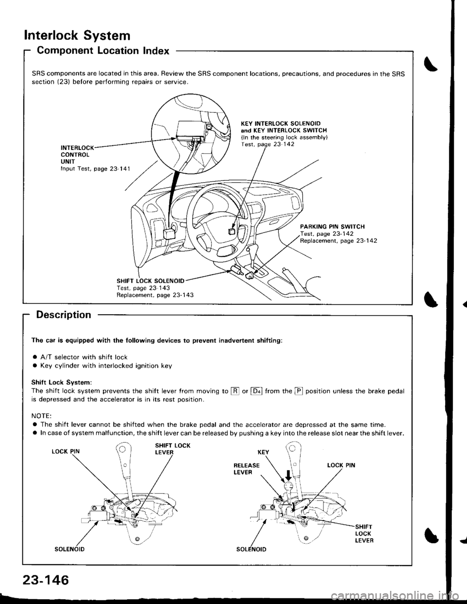
Component Location Index
Description
The car is equipped with the lollowing devices to plevent inadvertent shifiing:
a A/T selector with shift lock
a Key cylinder with interlocked ignition key
Shift Lock Svstem:
The shift lock system prevents the shilt lever trom moving to @ or [6ol from the p position unless the brake pedal
is depressed and the accelerator is in its rest position.
NOTE:
a The shift lever cannot be shifted when the brake pedal and the accelerator are depressed at the same time.
a In case of system malfunction, the shift lever can be released by pushing a key into the release slot near the shift lever.
SRS components are located in this area. Review the SRS component locations, precautions, and procedures in the SRS
section (23) belore performing repairs or service.
KEY INTERLOCK SOLENOIDand KEY INTERLOCK swlTCH
{ln the steering lock assembly}
INTERLOCKCONTROLUNIT
PARKING PIN SWITCHTest, page 23-142Replacement, page 23-1 42
Replacement, page 23-143
SHIFT LOCK SOL€NOIDTest, page 23 143
23-146
Page 1204 of 1681
)
t
t
Description
Ths cal is equipped with the tottowing devices to prevent inadvertenl shifting:
a Key cylinder with interlocked ignition key (Key Interlock System)
a shift lever with shift lock (shilt Lock system)
Key Interlock System:
When the shift lever is in any other position than @ or is not securely locked in @ (parking pin switch is ON), a solenoid
is activated, making it impossible to remove the ignition key from the ignition switch.
To be able to remove the key, the shift lever must be in E] and must be securely locked in this position {parking pin
switch must be turned oft by the lock pin)
The shift lever is in any othel position than El and the psrking pin switch is ON:
CYLINDER
The shitt lever is in l!] and the parking pin switch is OFF:
KEY CYLINOER
PARKING PIN
SHIFT LOCK LEVER
SHIFT LOCK LEVER
{t
23-147
Page 1213 of 1681
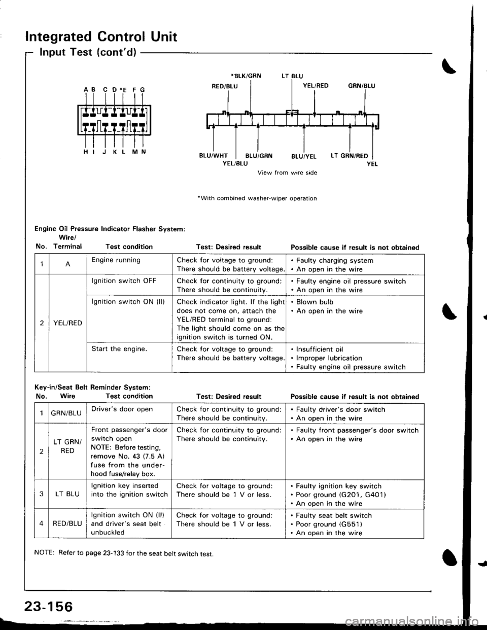
Integrated Control Unit
lnput Test (cont'd)
YEL/BLU
View from wire side
'With combined washer-wiper operation
Engine Oil Pressure Indicator Flasher System:
Wire/
No. TerminalTest condition
Key-in/Seat Belt Reminder System:
No. WileTest condition
Testi Desired result
Test: Desired result
Possible cause if result is not obtainsd
Possible cause if fesult is not obtained
*BLK/GRN
1Engine runningCheck for voltage to ground:
There should be battery voltage.
. Faulty charging system. An open in the wire
2YEL/RED
lgnition switch OFFCheck for continuity to ground:
There should be continuity.
. Faulty engine oil pressure switch. An open in the wire
lgnition switch ON (ll)Check indicator light. It the light
does not come on, attach the
YEL/RED terminal to groundl
The light should come on as the
ignition switch is turned ON.
. Blown bulb. An open in the wire
Start the engine.Check tor voltage to ground:
There should be battery voltage
lnsufticient oil
lmproper lubrication
Faulty engine oil pressure switch
1GRN/BLUDriver's door openCheck for continuity to ground:
There should be continuity.
. Faulty driver's door switch. An open in the wire
2
LT GRN/
RED
Front passenger's door
swrlcn open
NOTE: Before testing,
remove No. 43 {7.5 A)
fuse from the under-
hood fuse/relay box.
Check for continuity to ground:
There should be continuity.
. Faulty front passenger's door switch'An open in the wire
3LT BLU
lgnition key inserted
into the ignition switch
Check for voltage to ground:
There should be 1 V or less.
Faulty ignition key switch
Poor ground (G2O1, G401 l
An open in the wire
4RED/BLU
lgnition switch ON (lll
and driver's seat belt
unbuckled
Check for voltage to ground:
There should be 1 V or less.
Faulty seat belt switch
Poor ground (G551l
An open in the wire
NOTE: Refer to page 23-133 for the seat belt switch test.
Page 1215 of 1681
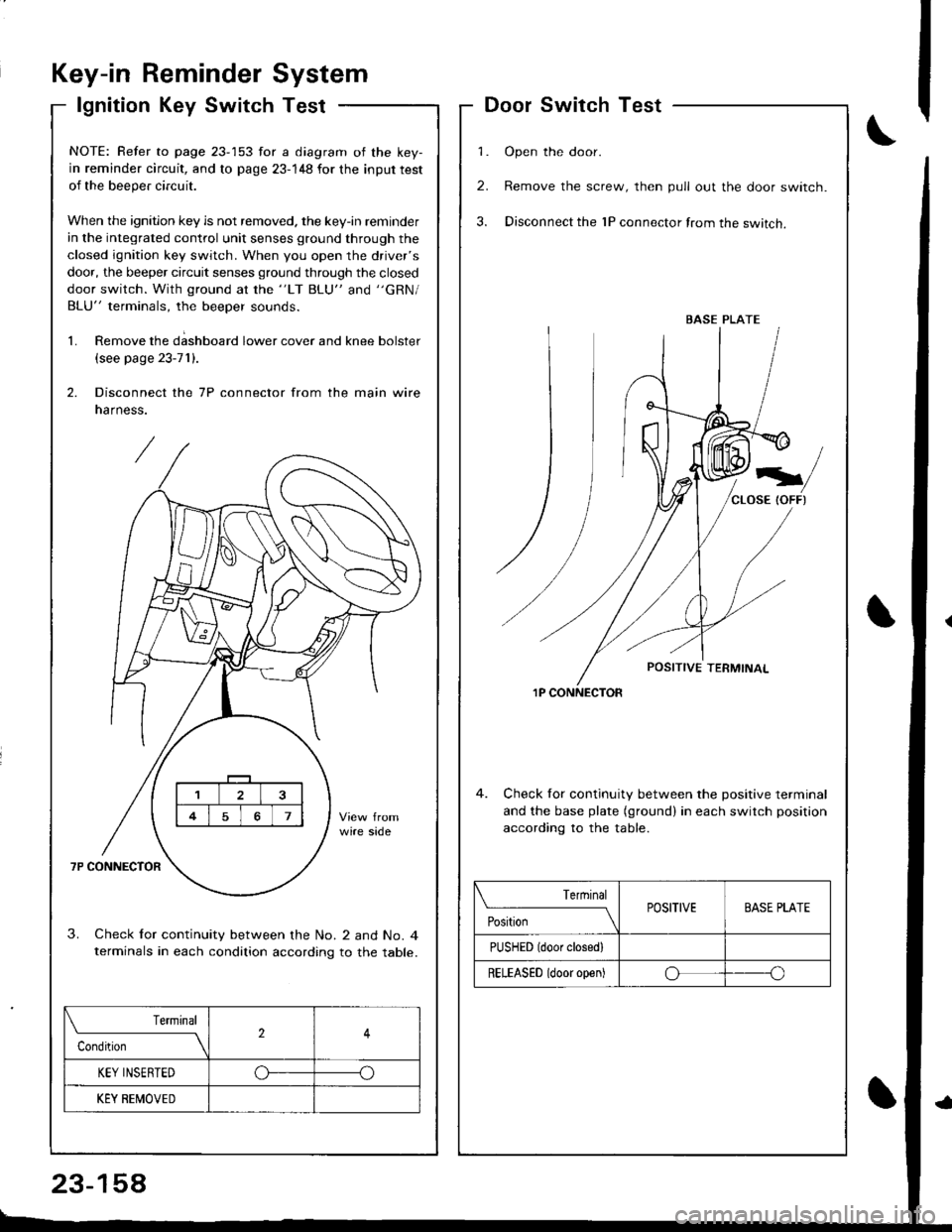
Key-in ReminderSystem
lgnition Key SwitchTest
\f
DoorSwitchTest
1. Open the door.
2. Remove the screw, then pull out the door switch.
3. Disconnect the 1P connector from the switch.
1P CONNECTOR
4. Check for continuity between the positive terminal
and the base plate (ground) in each switch position
accordinq to the table.
BASE PLATE
Terrninal
PositionPOSITIVEBASE PLATE
PUSHED (door closedl
RELEASED (door open)oo
NOTE: Refer to page 23-153 for a diagram of the key-
in reminder circuit, and to page 23-148 for the input test
of the beeper circuit.
When the ignition key is not removed. the key-in reminder
in the integrated control unit senses ground through the
closed ignition key switch. When you open the driver's
door, the beeper circuit senses ground through the closed
door switch. With ground at the "LT BLU" and "GRN/
BLU" terminals, the beeper sounds.
1. Remove the d;shboard lower cover and knee bolster
(see page 23-71).
2. Disconnect the 7P connector from the main wire
narness.
3. Check lor continuity between the No. 2 and No. 4terminals in each condition according to the table.
Terminal
Condition2
KEY INSERTEDo--o
KEY BEMOVED
23-158
Page 1222 of 1681
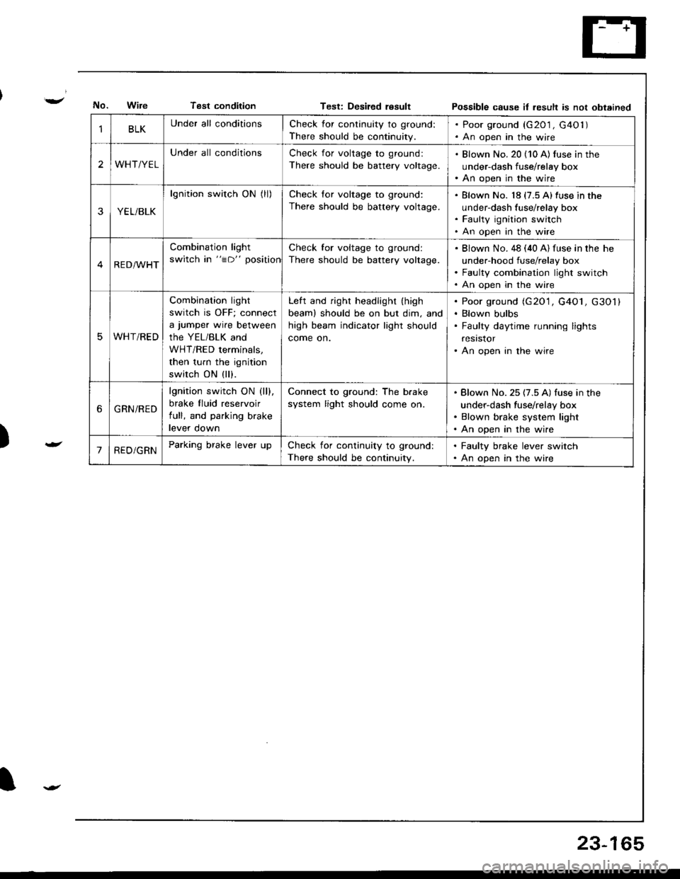
Tsst conditionTest: Desiled resultPossible cause it result is not obtained
)
BLKUnder all conditionsCheck for continuity to ground:
There should be continuity.
. Poor ground (G201 , G40l ). An open in the wire
2WHT/YEL
Under all conditionsCheck for voltage to ground:
There should be battery voltage.
. Blown No. 20 (10 A) fus€ in the
under-dash fuse/relay box. An open in the wire
YEL/BLK
lgnition switch ON (ll)Check for voltage to ground:
There should be battery voltage.
Blown No. 18 (7.5 A)fuse in the
under-dash fuse/relay box
Faulty ignition switch
An open in the wire
RED/WHT
Combination light
switch in "=D" position
Check for voltage to ground:
There should be battery voltage.
Blown No. 48 (40 A) fuse in the he
under-hood fuse/relay box
Faulty combination light switch
An open in the wire
WHT/RED
Combination light
switch is OFF; connect
a jumper wire between
the YEL/BLK and
WHT/RED terminals,
then turn the ignition
switch ON (ll).
Left and right headlight (high
beaml should be on but dim, and
high beam indicator light should
come on.
Poor ground (G20'1, G4O1, G301)
Blown bulbs
Faulty daytime running lights
resrstor
An open in the wire
6GRN/RED
lgnition switch ON (ll).
brake fluid reservoir
full, and parking brake
levef oown
Connect to ground: The b.ake
system light should come on.
Blown No. 25 (7.5 A) fuse in the
under-dash fuse/relay box
Blown brake system light
An open in the wire
'1RED/GRNParking brake lever upCheck for continuity to ground:
There should be continuity.
. Faulty brake lever switch. An open in the wire
23-165