Page 1063 of 1681

Troubleshooting
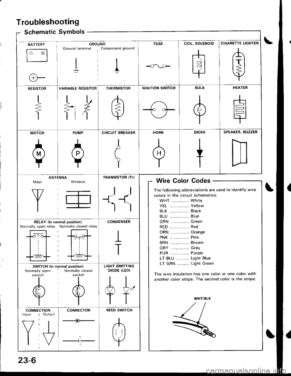
Schematic Symbolsym
BATTEBY
tr3
o-
GROUNDGround terminal Componenr ground
I il
FUSE
COIL, SOLENOID
rhtdl
l9l.|
CIGARETTE LIGHTER
,A
lrl
Y
RESISTOR
+
T
VARIABLE RESISTOR
TD
=rX
ttf
THERMISTOR
/b'
t=l
v
IGNITION SWITCH
1-\-T- l.--
BULB
A
Y
HEATER
-h
t=l
tr
MOTOR
0
PUMP
A
Y
CIRCUIT EREAKER
I
t
Y
HORN
+
DIODE
+
SPEAKER, BUZZER
D
Mast
Y
ANTtiNNA
T,
TRANSISTOR (Tr)
ll
+1^'l
)
Wire Color Codes
The following abbreviations are used to identify wire
colors in the circuit schematics:
WHT ............ White
YE1 .............. Yellow
81K .............. Black
B1U .............. Blue
GRN ............. Green
RED .............. Red
ORN ............. Orange
PNK .............. Pink
BRN .............. Brown
GRY ............. Gray
PUR .............. Purple
LT BLU ......... Light Blue
LT GRN ......... Light Green
The wire insulation has one color or one color with
another color stripe.'The second color is the stripe.
WHT/BLK
,//,aI,//t- /
R
BELAY lln noNormally open relayrmal position)
Normally closed relay
-tr-f,-
l=T= |
til
trf
CONDENSER
I
T
SWITCH {ln nrNormally openswitch
I
/6\
v
I
)rmal position)Normally closed
I
A
w
I
LIGHT EMITTINGDIODE (LEDI
AJ"
YT
CONNE
V
I
CTIONOutput
J,
CONNECTOR
+>-
l-l'l
REED SWITCH
.K
Irr ]
Y
Page 1105 of 1681
![HONDA INTEGRA 1998 4.G Workshop Manual Fuses
Under-dash Fuse/Relay Box
C920 [To SRS msin harnc$ lc8{,l}lC922 [To ignition rwitchl
C923lTo main wir. harn6! (Cil,alll
C€24 [To m.in wiro hrrno$ lc,l,l2]l
lTo pow.r windowrclayl
CgNlS Oo turn HONDA INTEGRA 1998 4.G Workshop Manual Fuses
Under-dash Fuse/Relay Box
C920 [To SRS msin harnc$ lc8{,l}lC922 [To ignition rwitchl
C923lTo main wir. harn6! (Cil,alll
C€24 [To m.in wiro hrrno$ lc,l,l2]l
lTo pow.r windowrclayl
CgNlS Oo turn](/manual-img/13/6069/w960_6069-1104.png)
Fuses
Under-dash Fuse/Relay Box
C920 [To SRS msin harnc$ lc8{,l}lC922 [To ignition rwitchl
C923lTo main wir. harn6! (Cil,alll
C€24 [To m.in wiro hrrno$ lc,l,l2]l
lTo pow.r windowrclayl
CgNlS Oo turn 3ign.l/h.z.rd rcl.yl
C919 [To root wir. hsmolr {C661ll
al Spare fusel: Option connector (+B)
2: Option conn€ctor (oash lights)3: Option connector (ACC)
4: Option connector {lG2}*: Not us€d
Fusa Number Amp!wire Color
C928 [To r..] window d.toggd r.l.yl
Compon€nt(s) or Circuit(3) Protaqtad
C92l ITo d..hbo.rd wir. h.rness lc551ll
- r-t r-'l r-'t n n r-'t n n r-1 r-'l r-l4 2321 2s 26 27 28 29 30 3t 32 33IJ IJ IJ LI LI IJ LI LJ IJ LI LJ I.J
- r-t n n r-l r-'t r-t r-'l r-1 n r-'t r-1a 12 13 14 15 t6 17 ,t8 19 20 21 22I-J LI IJ IJ tJ LI LI IJ IJ IJ LI IJ
- r-'t |;l n r-1 n |;t r-'t r-t r-1 n r-'ta 12 3 it 5 67 8 910 11
LI IJ IJ IJ LI IJ LI LI I-J LI LJ LI
1204WHT/GRNPower door lock control unit
Not used
10AGRN,4/VHTRear window washer motor
GRN/BLKRear window wioer motor
410 ARED/BLURight headlight (high beam)
10ARED/GRNLeft headlight (high beam), high beam indicator light
Not used
720A.GRN/BLKLeft rear power window motor
a204YEUBLKRight rear power window motor
15 ABLK/YELlgnition coil
10204BLU/BLKPasseflger's power window motor
l1204WHTI/ELPower window master switch, power window control unit
23-48
Page 1115 of 1681
Power Distribution
N0.54 (404)FUSE(From page 23 55)
N0.49 (30A)FUSE(From page 23-55)
Gircuit ldentification (cont'dl
UNDER.DASH FUSEi FELAY BOX
(Fuserelay box sockel)Oplional conneclor (+B)
N0.50 (40A) FUSE(From page 23-55)
'/'/H_'GRN ----- rower door tock controt un,tF Halct op€ler acluatorl- Halch lalcn sw,rm
BLKGFN <- BLKRED - Rear window delogger
N0.16 (7.sA) FUSE(Viaswlch)
f7
IBLUfrEL
IGNITION SWITCHlFrom page 23 56)
ft
IWHT/BLK
"^--f,_
(Fus€irglay box soclel)
G201G401
Cigaretle lighler
Oplional conneclor (ACC)
Audro unil conneclorWHT/GRN
23-58
Page 1130 of 1681

;
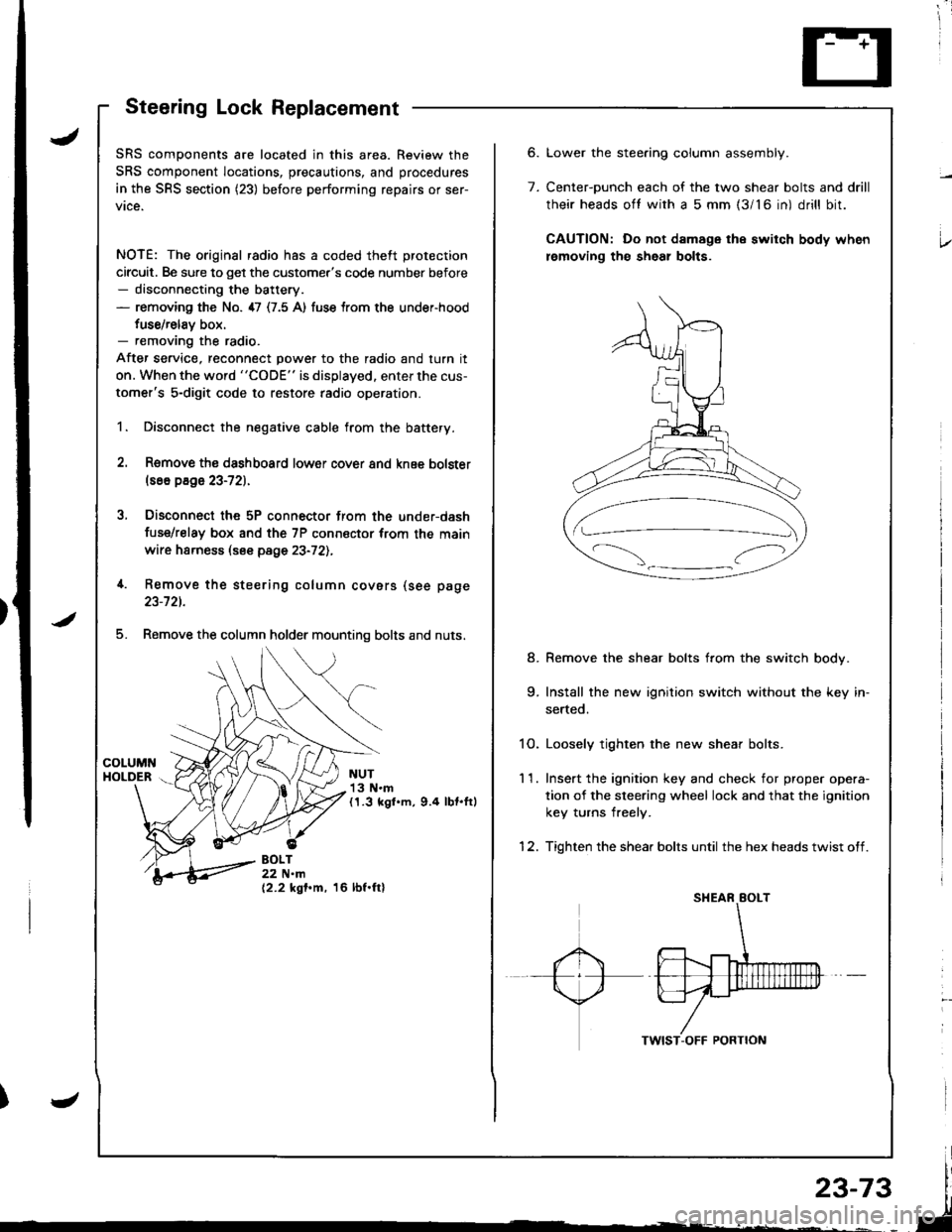
Steering Lock Replacement
SRS components are located in this area. Review the
SRS component locations, precautions, and procedures
in the SRS section (23) before performing repairs or ser-
vice.
NOTE: The original radio has a coded theft protection
circuit. Be sure to get the customer's code number before- disconnecting the battery.- removing the No. 47 (7.5 A) fuse trom the under-hood
fuse/relav box.- removing the radio.
After service, reconnect power to the radio and turn it
on. When the word "CODE" is displayed. enter the cus-
tomer's 5-digit code to restore radio operation.
1. Disconnect the negative cable from the battery.
2. Remove ths dsshboard lower cover and knee bolster(s6o p8ge 23-72).
3, Disconnect the 5P connector from the under-dash
fuse/relay box and the 7P connsctor from th€ main
wire harness (see page 23-72l.,
4. Remove the steering column covars (see page
23-721.
5. Remove the column holder mounting bolts and nuts.
NUT13 N.m(1.3 kgl.m, 9.4 lbt.ftl
BOLT22 N.m(2.2 kgf.m, 16 lbf.ftl
6.
7.
Lower the stee.ing column assembly.
Center-ounch each of the two shear bolts and drill
their heads oft with a 5 mm {3/16 in) drill bit.
CAUTION: Do not damage the switch body when
lemoving th€ sheal bolts.
Remove the shear bolts from the switch body.
Install the new ignition switch without the key in-
serted.
1O. Loosely tighten the new shear bolts.
11. Ins€rt the ignition key and check for proper opera-
tion of the sleering wheel lock and that the ignition
key turns freely.
12. Tighten the shear bolts until the hex heads twist off.
8.
Page 1132 of 1681
Circuit Diagram (M/Tl
tJ
STARTEBCUT RELAY
)/
ll-G2o1G401
rAa rtFz5- r3
) -rr
CLUTCHINTERLOCKSW]TCH
IGNITIONX SWITCH
!_*",.^-*-G-l
"T"
BTKWHT BLKWHT
llr - tr |
BLKFED 8LU/BLK
- BLK,BE' I__-lrror.oo*
I I
+Yffii'"'Tf'o' | |
u"T-l
i,t^il'r** | |
=-T--. I
twt t
l$*Tl r
IA II
BLK
tY--lt I-|ffim-
|
rl
UNDEB HOOD FUSE/BELAY BOX
No 41 (100A) N0.42 (404)
Page 1133 of 1681
Starting System
Circuit Diagram (A/T)
IGNITIONSWITCH
/ BAT \--i.o
\jz IIBLKWHT
II
I
rl., - oro,( lI ) POStlOr\l swrTcHY+'/ {Nedtal Posilion swilch)
II
IELIVRED
WHT/BLK +WHT
::--JFUSBFELAYBox
ISLIffiED
I
IGBY/BLU]
J
ECM
STASTER(Field windiig ly!€)
UNDEF.HOOO FIJSE/RELAY BOX
BLI(YEL
N0.41 (100A) No.42 (40A)
23-76
Page 1134 of 1681

Ch6ck Starter Engag€mont;
1. Remove the No. 44 (15 A) fuse from the under-hood
fuse/relay box,
Press the clutch pedal all the way in (M/T), and turn
the ignition switch to "St8rt". The staner should
crank the engine,
NOTE: On cars equipped with manual transmission,
the engine will not crank unless the clutch pedal is
fully depressed.
lf the starter does not crank the engine, go to step 3.
Check the battery, battery positive cable, ground,
and the wire connections for looseness and cor-
rosion.
Test again. lf the stsner stilldoes not crank the en-
gine, go to step 4.
Bypass the ignition switch circuit as follows {make
sure the transmission is in neutral)
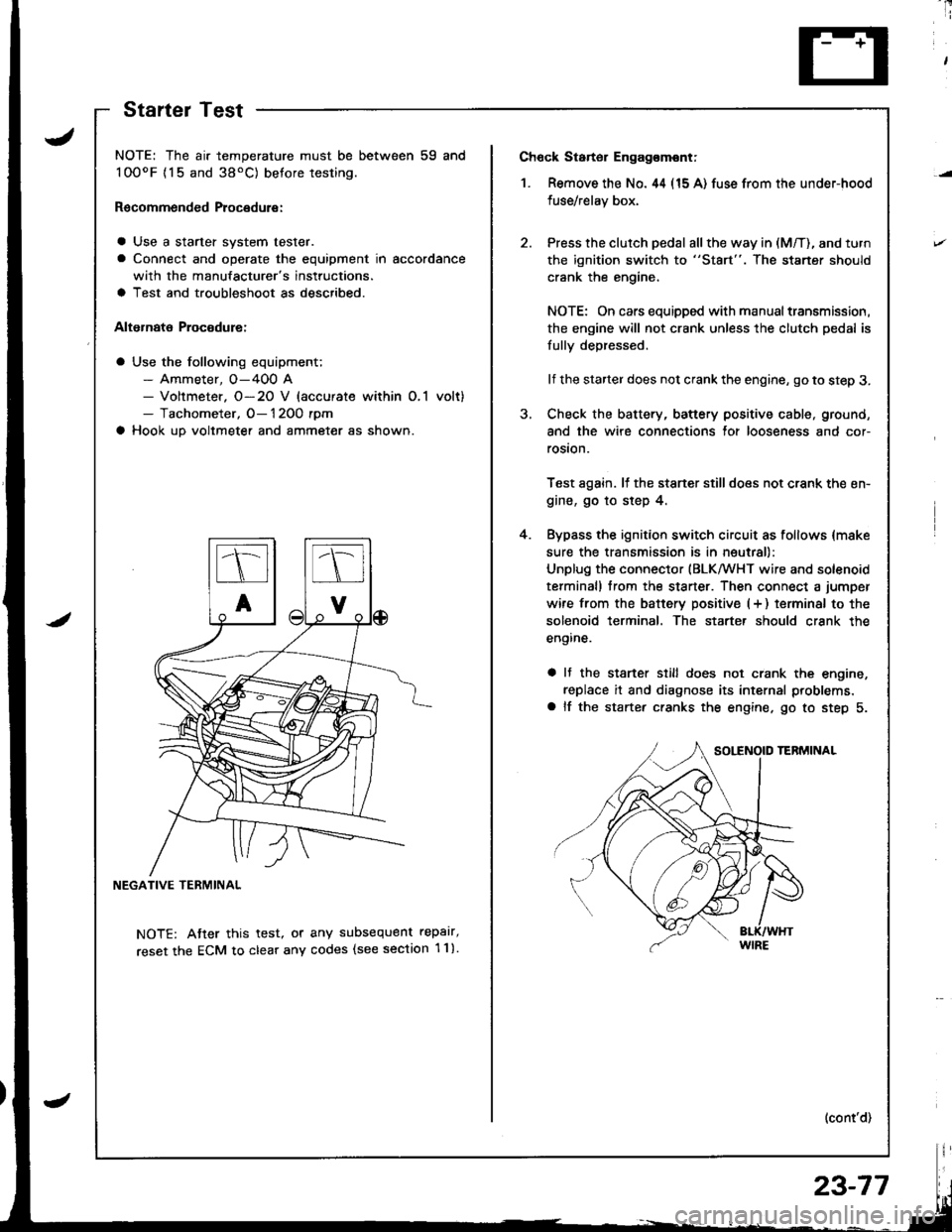
Unplug the connector (BLKMHT wire and solenoid
terminal) trom the staner. Then connect a jumper
wire from the batterv positive (+ ) terminal to the
solenoid terminal. The starter should crank the
engine.
a It the stsrter still does not crank the engine,
replace it and diagnose its internal problems,
a lf the starter cranks the engine. go to step 5.
(cont'd)
4.
NOTE: The air temperature must be between 59 and
100oF {15 and 38'C) betore testing.
Recommended Procedure:
a Use a starter system tester.
a Connect and operate the equipment in accordance
with the manufacturer's instructions.
a Test and troubleshoot as described.
Alternate Procodure:
a Use the following equipment;- Ammeter, O-400 A- Voltmeter. O-20 V (accurate within O,1 volt)- Tachometer, O- 1 2OO rpm
a Hook up voltmeter and ammeter as shown.
NEGATIVE TERMINAL
NOTE: Atter this test, or any subsequent repalr,
reset the ECM to clear any codes (see section 1 1).
StartelTest
23-77
Page 1135 of 1681

Starting System
Starter Test (cont'dl
Check Cranking rpmr
Engine speed during cranking should be above 1OO rpm.
lJ speed is too low, check for:
a Loose batlery or starter terminals
a Excessively worn starter brushes
a Open circuit in commutator segments
a Dirty or damaged helical spline or drive gear
a Defective drive gear overrunning clutch
Check Starter Disengagement:
Press the clutch pedal all the way in (M/T), turn rhe igni
tion switch to "lll" and release to "11".
The starter drive gear should disengage from the flywheel
or torque converter ring gear when you release the key.
It the drive gear hangs up on the flywheel or torque con-
verter ring gear, check for:
a Solenoid plunger and switch mallunction
a Dirty drive gear assembly or damaged overrunning
clutch
5. Check for an open in the BLK/WHT wire circuit be
tween the starter and ignition switch, and con-
necrors,
6. Check the ignition switch (see page 23-71).
7. On cars with automatic transmission, check the A/Tgear position switch (neutral position switch) and
connector. On cars with manualtransmission, check
the starter cut relay, clutch interlock switch, and
connectors.
NOTE: Check the No. 42 (40 A) fuse in the under,hoodfuse/relay box for the starter cut relay.
Check Jor Wear and Damage:
The starter should crank the engine smoothly and stead,ily. lf the starter engages, but cranks the engine errati
cally, remove it. Inspect the starter, drive gear, andllywheel or torque converter ring gear lor damage.
a Check the drive gear overrunning clutch for binding
or slipping when the armature is rotated with the drivegear held. Replace the gears i{ damaged.
Check CJanking Voltage and Current Draw:
Cranking voltage should be no less than 8.O volts.
Current draw should be no more than * amperes.* 1.2 kW: 27O A
1 .4 kW: 360 A
It cranking voltage is too low, or current draw too high,check for:
a Dead or low charged batterya Open circuit in starter armature commutator segmentsa Starter armalure dragging
a Shorted armature windinga Excessive drag in engine