Page 999 of 1681
Troubleshooting
Blower Motor (cont'd)
From page 21-11\View from wire side
8LU/BLK( + I
Turn the ignition switch OFF.
Remove the heater control panel(see page 21-25).
Turn the ignition switch ON lll).
Measure the voltage between theBLU/BLK wire terminal {+) andbody ground (- ).
Repair open in the BLU/Bl-K wir6between the blowea motor andthe hoster lsn switch.ls there battery voltage?
Turn the ignition swirch OFF.
Check for continuity in the BLKwire between the heater fanswitch and body ground.
Check fo. an oDen in th6 8LK wirebotwo€n th€ haat€r tan switchand body ground. ll th6 whe isOK. check tor poor ground atG201 and 401.
Rsplac€ the heat€r fan switch.
ls there continuity?
Page 1000 of 1681
From page 21-11
BLOWER MOTOR RELAY /rp SOCKETTurn the ignition switch ON {ll).
Measure the voltage between theNo. 4 terminal (-f ) and bodyground (- ).
Repair open in the BLK/YEL wirebetweon tho under-hood tuse/r€-lav box and th€ und€r-drshtuse/relav box.
ls there battery voltage?
Turn the ignition swrtch OFF.
Check for continuity between theNo. 2 terminal and body ground.
Check for an oDen in the BLK wir€belween the undor-hood fuso/re-lay box and body ground. It thewire is OK, check forpoor groundat G201 and G4O1.
Ropair open in the BLU/WHT wirebetween the undor-hood fuse/re-lav box and the blow€r motor.
21
4
Page 1001 of 1681
Troubleshooting
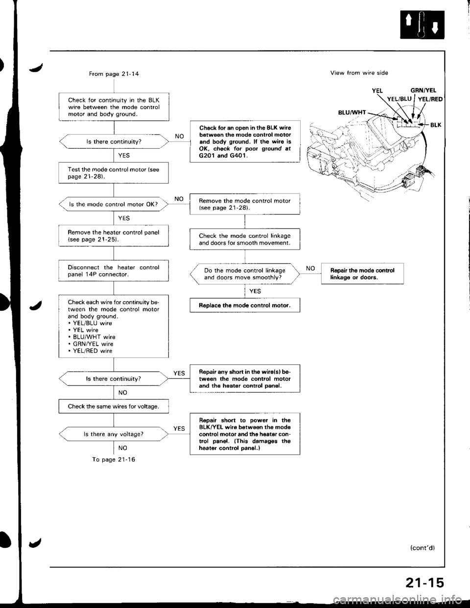
Mode Control Motor
Mode controlmotor does nol run.or ong or more mode are in-operatve.
Disconnect the mode control mo-tor 8P connector.
Turn the ignrtion switch ON (ll).
Measurethe voltage between theBLK/YEL wire terminal {+ ) andbody ground (- ).
Repair open in ths BLK/YEL wirebetween the und€r-dash fusehe-lay box and the mods cont.olmotoa,
Turn the ignition swirch OFF.
ls there battery voltage?
To page 21 15
21-14
Page 1002 of 1681

II
JFrom page 21- 14
ls the mode control motor OK?
YES
NO
To page 21-16
View from wire side
BLU/WHT
GRNTYEL
(cont'dl
Check for continuily in the BLKwire between the mode controlmolor and body ground.
Check tor an oDen in the BLK wireb€twe€n the mode control motorand body ground. lf the wiro isOK, check for poor ground atG201 and G401.
Test the mode conlrol motor (seepage 21-281.
Remove the mode control motor(see page 21-28).
Remove the heater control panel
lsee page 21-25).Check the mode control linkageand doors for smooth movement,
Disconnect the heater controlpanel 14P connector.Ropair the modo contrcllinkag€ or doors.Do the mode control linkageand doors move smoothly?
Check each wire for continuity be-tween the mode control motorand body ground.. YEL/BLU wire. YEL wire. BLU/WHT wire. GRN/YEL wire' YEL/RED wire
ReDlace the mode conlrol molor.
Ropaii any short in the wiiolslbe-tw6€n the mod€ control motorand th€ heater control oan6l,
Check the same wires for voltaoe,
Ropair sho.t to power in theBLK/YEL wir€ betweon the mod€controlmotor and the hottor con-trol panel. (This damagos thgheater control oanel.)
ls there any voltage?
,.i:...
''{
'rt'',-
21-15
Page 1004 of 1681
Recirculation Control Motor
Recirculation contiol door doosnot change b6tw66n FRESH andRECIRCULATE.
Disconnect the recirculation control motor 4P connector.
Turn the ignition switch ON (lll.
Measure the voltage between theBLK/YEL wire terminal (+l andbodv ground 1- ).
Repair opon in the 8LK/YEL wirebotwo€n th6 undeFdaah fus6/r6-lay box and ths .acirculation con-lrol motor.
ls there battery voltage?
lurn the ignition switch OFF.
To p6ge 21-18
{cont'd)
21-17
Page 1005 of 1681

Troubleshooting
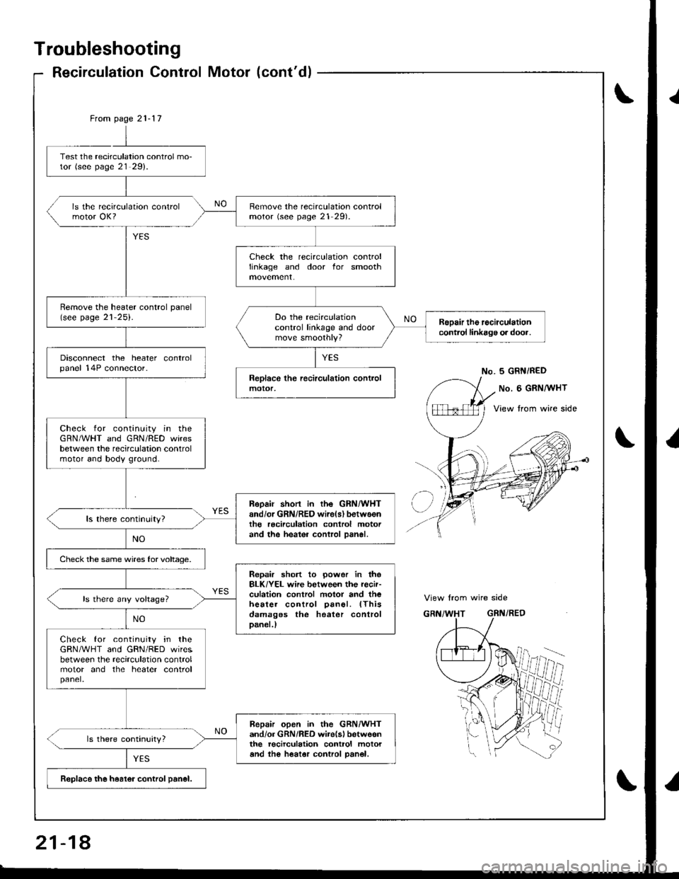
Recirculation Control Motor (cont'dl
\
From page 21-17
Remove the recirculation controlmotor (see page 21 291.
Check the recirculation controllinkage and door for smooth
Remove the heater control panel(see page 21-25).Do the recirculationcontrol linkage and doormove smoothly?
Rspair the recirculationcontrol linkagg o. door.
Disconnect the heater controlpanel 14P connector.
Check for continuity in theGRN/WHT and GRN/RED wiresbetween the recirculation controlmotor and bodv ground.
Reoair short in the GRN/WHTand/or GRN/REO wire(s) betweentho recirculation control motorand the heaioi control Dan6l.
Check the same wires for voltage.
Repair short to power in thoBLK/YEL wire between the recir-culation control motor and theheater control oanel. lThisdamages the heater controlDan€|.)
ls there 6ny voltage?
Check for continuity in theGRN/WHT and GRN/RED wiresbetween the recirculation controlmotor and the heater controlpanel.
Bepair open in the GRN/WHTand/or GRN/RED wirelsl betw6enthe recirculation control motorand the heator control Dan€|.
Replace the h6alor control panel.
Test the recarculation control mo-tor (see page 21 2g).
ls the recirculation controlmotor OK?
No. 5 GRN/RED
View from wire side
21-18
Page 1006 of 1681
1i
II
Heater Control Panel Input/Output Signals
No.Wire ColorSignalNo.Wile ColorSignal
BLU/WHTHEATINPUT8GRN/YELHEAT/VENTINPUT
2YELHEATiDEFINPUTqRED/BLKCOMBINATION LIGHT SWICHINPUT
3YEL/BLUDEFINPUT10REDBRIGHTNESS CONTROLLEROUTPUT
BLKGROUNDOUTPUT11BLU/REDA/C THERMOSTATINPUT
5GRN/REDRECIRCULATEINPUTGRNHEATER FAN SWITCHOUTPUT
6GRN/WHTFRESHINPUT
7YEL/REDVENTINPUT14BLK/YELINPUT
21-19
Page 1008 of 1681
NOTE:
a Before reassembly, make sure that the recirculation control door and linkage move smoothly without binding.a When reattaching the recirculation control motor. make sure its positioning will not allow the recirculation control doorto be pulled too far. Attach the recirculation control motor and all links, then connect power and ground, and watchthe movement of the recirculation control door.
RECIRCULATIONCONTROL MOTORTest, page 21-29
BLOWER RESISTORTost, page 21-9
gBLOWERMOTORTest, page 21-11
Replacement, page 21-29
,/],�
Overhaul
21-21