Page 656 of 2189
Gountershaft Assembly
Disassembly
1. Securely clamp the countershaft assemblv in a
bench vise with wood blocks.
2. Raise the locknut tab from the groove in the coun-
tershaft, then remove the locknut and the spring
washer.
Remove the ball bearing using a bearing pulle. asshown.
BEARING PULLER
BALL BEARING
13-76
4, Remove the bearing outer race, then remove theneedle bearing using a bearing puller as shown.
BEARING PULLEF
BEARING
CAUTION: Romove the gears using a pr63 and the
stesl blocks as shown, Use of a ,aw-typo puller can
cause damage lo lhe gear tooth.
Support 4th gear on steel blocks, and press thecountershaft out of sth and 4th gears, as shown.
sTH GEAF
{TH GEAR
.(
a
ItI
Page 659 of 2189
9. Support the countershaft on a steel block, and
install 4th gear using the special tools and a press.
as 5nown.
ATTACHMENT,35 mm LD.07746 - 0030400
Support the countershaft on a steel block, and
install 5th gear using the special tools and a press,
as shown.
ATTACHMENT, 30 mm I,D,07746 - 0030300
10.
\
'1'1. Install the needle bearing, then install the ball bear-
ing using the special tools and a press as shown.
PRESSDRIVER,40 mm LD.07746 - 0030100
ATTACHMENT,30 mm LD.07746 - 0030300
J.-12.Securely clamp the countershaft assembly in a
bench vise with wood blocks.
lnstall the spring washer, tighten the locknut, then
stake the locknut tab into the groove.
LOCKNUT
108- 0- 108N.m 111.0- 0- 11.0kgt.m,
80+ 0* 80 lbf'ftl
WOOD BLOCKS
13-79
Page 674 of 2189
Transmission
Reassembly (cont'dl
Install the dowel pins.
Install the transmission housing by aligning thegroove in the housing with the finger on the stopfl ng.
GROOVE
21.
Lower the transmission housing with the snap ringpliers, and set the snap ring in the groove of thecountershaft bearing.
TRANSMISSIONHOUSING
13-94
(
23. Check that the snap ring is securely seated in thegroove of the countershaft bearing.
Dimension 6) as instalt6d: 4.6 - 8.3 mm(0.181 - 0.327 inl
24.Install the clutch line bracket, transmission hangerA and back-up light switch ctamp, then tighten thetransmission housing attaching bolts in the num_bered sequence shown below.
ATTACHING BOLTS8 x 1.25 mmTRANSMISSIONHANGER A27 N m 12.8 kgtm, 20 tbt.trl
BACK.UP LIGHTSWITCH CLAMP
lar---'o o
"W
Page 784 of 2189

Shift Control Solenoid Valve A/B Assembly
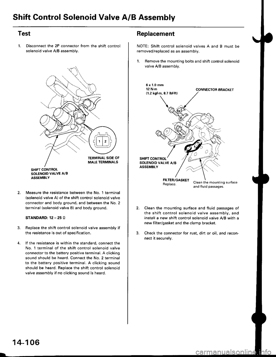
Test
1. Disconnect the 2P connector from the shift control
solenoid valve A,/B assemblv.
SHIFT CONTROLSOLENOID VALVE A/B
ASSEMBLY
N4easure the resistance between the No. 1 terminal(solenoid valve A) of the shift control solenoid valve
connector and body ground, and between the No. 2
terminal (solenoid valve B) and body ground.
STANDARD: 12 - 25 O
Replace the shift control solenoid valve assembly if
the resistance is out of specification,
lf the resistance is within the standard, connect the
No. 1 te.minal of the shift control solenoid valve
connector to the battery positive terminal. A clicking
sound should be heard. Connect the No. 2 terminal
to the battery positive terminal. A clicking sound
should be heard. Replace the shift control solenoid
valve assembly if no clicking sound is heard.
14-106
Replacement
NOTE: Shift control solenoid valves A and B must be
removed/replaced as an assembly.
1. Remove the mounting bolts and shift control solenoid
valve A,/B assembly.
5xL0mm12 N.m(1.2 kgf.m,8.7 lbf.ft)CONNECTOR BRACKET
FILTER/GASKETBeplace.Clean the mounting surfaceand fluid passages.
Clean the mounting surface and fluid passages of
the shift control solenoid valve assembly, and
install a new shift control solenoid valve Ay'B with a
new filter/gasket and the clamp bracket.
Check the connector for rust. dirt or oil. and recon-
nect it securelv,
Page 807 of 2189

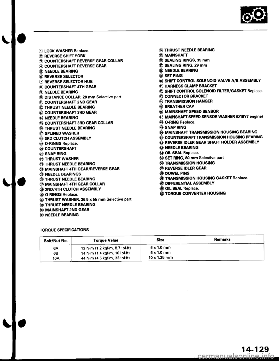
O LocK WASHER Replace,
O REVERSE SHIFT FORK
O COUNTERSHAFT REVERSE GEAR COLLAR
G) COUNTERSHAFT REVERSE GEAR
@ NEEDLE BEARING
@ REVERSE SELECTOR
O REVERSE SELECTOR HUB
@ COUNTERSHAFT 4TH GEAR
O NEEDLE BEARING
@ DISTANCE GOLLAR, 28 mm Selective part
O COUNTERSHAFT 2ND GEAR
@ THRUST NEEDIE BEARING
@ COUNTERSHAFT 3RD GEAR
@ NEEDLE BEARING
@ COUNTEBSHAFT 3RD GEAR COLLAR
@ THRUST NEEDLE BEAFING
O SPLINED WASHER
@ 3RD CLUTCH ASSEMBLY
@ O-RtNGs Replace.
@ COUNTERSHAFT
@ SNAP RING
@ THRUST WASHER
€) THRUST NEEDTE BEARING
@} MATNSHAFT 4TH GEAR/REVERSE GEAR
@i NEEDLE BEARINGS
@ THRUST NEEDLE EEARING
@) MAINSHAFT 4TH GEAR COLLAR
@ 2ND/4TH CLUTCH ASSEMBLY
@ o-RlNGs Replace.
@ THRUST WASHER,36.5 x 55 mm Sel€ctive part
@ THRUST NEEDLE BEARING
@ MAINSHAFT zND GEAR
@ NEEDLE BEARING
@ THRUST NEEDLE BEARING
@ MAINSHAFI
@ S€ALING RINGS, 35 mm
@ SEALING RING,29 mm
@} NEEDIE BEARING
@ SET RING
@ sHrFT CONTROL SOLENOID VALVE A/B ASSEMSLY
@ HARNESS CLAMP BRACKET
@ SHIFT COI,ITROL SOI"ENOID FILTER/GASKET Replace.
@ CONNECTOR BFACKET
@D TNANSMISSION HANGER
@ BREATHER CAP
@ MAINSHAFT SPEED SENSOR
@ MATNSHAFT SPEED SENSOR WASHER {Dl6Y' ongine}
@ O-RING Replace.
@ SNAP RING
@ MAINSHAFT TRANSMISSION HOUSING BEARING
@ OOUNIERSHAFT TRANSMISSION HOUSING BEARING
@ REVERSE IDLER GEAR SHAFT HOLDER ASSEMBLY
@ NEEDI.E BEARING
@ olL SEAL Replace.
@ SET RING, fll mm Selective part
@ rnANsMrssloN HouslNG
@ REVERSE IDI."ER GEAR
@ DowEL PINS
@ TRANSMISSION HOUSING GASKET Replace.
@ DIFFERENfIAL ASSEMBLY
@ OIL SEAL Replace.
@ TOROUE CONVERTER HOUSING
TOROUE SPECIFICANONS
Boh/Nut No.Torquo valueSizeRomarks
6B
10A
12 N.m {1.2 kgf.m,8.7 lbf.ft)
14 N.m (1.4 kgf'm, 10lbf'ft)
44 N.m (4.5 kgf.m, 33 lbf'ft)
6x1.0mm
6x1.0mm
10 x 1.25 mm
14-129
Page 865 of 2189

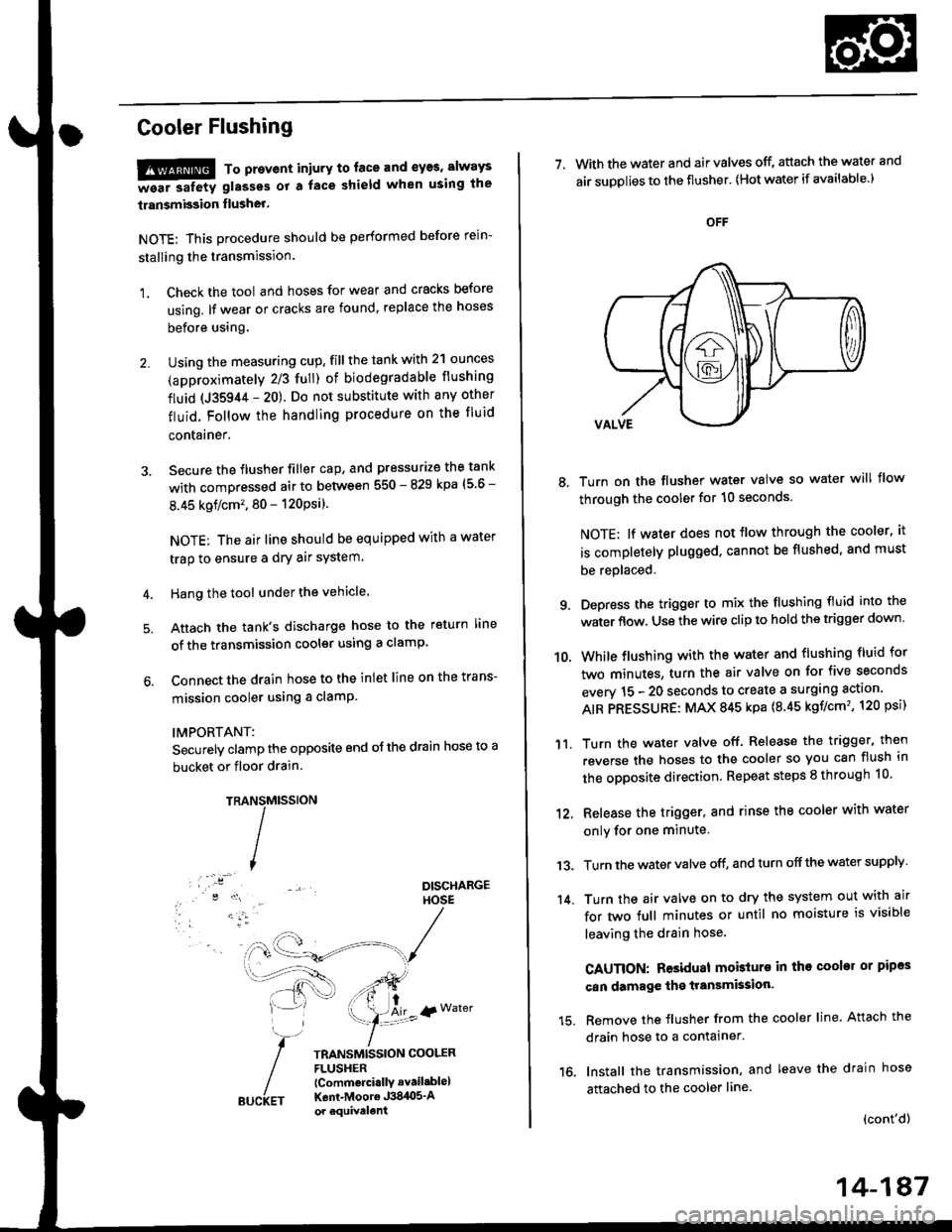
Cooler Flushing
!!!@ To prevent iniury to. face and eyas, always
-ea. safetv glasses ot a face shield when using the
transmission flusher.
NOTE: This procedure should be performed before rein-
stalling the transmission.
1. Check the tool and hoses for wear and cracks before
using. lf wear or cracks are found, replace the hoses
before using.
Using the measuring cup, fill the tank with 2'l ounces
(approximately 2/3 full) of biodegradable flushing
fluid (J35944 - 20). Do not substitute with any other
fluid. Follow the handling procedure on the fluid
contarner.
Secure the flusher filler cap, and pressurize the tank
with compressed air to between 550 - 829 kpa (5 6 -
8.45 kgflcm'�. 80 - 120Psi).
NOTE: The air line should be equipped with a water
trap to ensure a dry air system.
Hang the tool under the vehicle.
Attach the tank's discharge hose to the return line
of the transmission cooler using a clamp.
Connect the drain hose to the inlet line on the trans-
mission cooler using a clamP
IMPORTANT:
Securely clamp the opposite end oJ the drain hose to a
bucket or floor drain.
TRAMtssroN
TRANSMISSION COOLERFLUSHER{Commcrci.llY avail.blel
Kent-Moore J384O5'Aor equivelent
NS
I
{r Water
7. With the water and air valves off, attach the water and
air suDolies to the flusher' lHot water if available.)
8, Turn on the flusher water valve so water will flow
through the cooler for 10 seconds.
NOTE; lf water does not tlow through the cooler, it
is completely plugged. cannot be flushed, and must
be replaced.
9. Depress the trigger to mix the flushing fluid into the
water flow. Use the wire clip to hold the trigger down'
While flushing with the water and flushing fluid for
two minutes, turn the air valve on for five seconds
everv 15 - 20 seconds to create a surging action'
AIR PRESSURE: MAX 845 kpa {8.45 kgf/cm'�, 120 psi)
Turn the water valve off. Release the trigger, then
reverse the hoses to the cooler so you can flush in
the opposite direction. Repeat steps 8 through 10'
12, Release the trigger, and rinse the cooler with water
onlv for one minute
13. Turn the water valve off, and turn off the water supply
14. Turn the air valve on to dry the system out with air
for two full minutes or until no moisture is visible
leaving the drain hose.
CAUTION: Residual mobturo in tho cooler or pipas
can damage the transmksion'
15. Remove the flusher from the cooler line. Attach the
drain hose to a contalner.
16. Install the transmission, and leave the drain hose
attached to the cooler line
{cont'd)
10.
'11.
14-187
Page 916 of 2189
lf the self-diagnostic E indicator light does not blink, perform an inspection according to the table below.
SymptomInspectionRef. page
E indicator light does not come on for two seconds after ignition switch
is first turn on (ll).14-262
E indicator light is on constantly (not blinking) whenever the ignition
switch is on (ll).14-264
NOTE:
. lf a customer described the symptom for code P1706 (6), it will be necessary to recreate the symptom by test driving,
then recheck the DTC.
. Sometime the E indicator light and the Malfunction Indicator lamp (MlL) may come on simultaneously. lf so, repair the
pGM-Fl system according to the DTc, then reset the memory by removing the BACK uP fuse in the under-hood
fuse/relay box for more than 10 seconds. Drive the vehicle for several minutes at a speed over 30 mph (50 km/h)' then
recheck the DTC.
14-239
Page 918 of 2189
lf the self-diagnostic E indicator light does not blink. perform an inspection according to the table below.
SYmPtom
IDI indicator light does not come on for two seconds after ignition switch
is first turned ON (ll).
lE1 indicator light is on constantly (not blinking) whenever the ignition
switch is ON { ll).
InspectionRef. page
14-284
14-290
NOTE:
. lf a customer described the symptom for code Pl706 (6), it will be necessary to recreate the symptom by test driving,
then recheck the DTC.
. iometimes, tfre E indicator light and the Malfunction Indicator lamp (MlL) may come on simultaneously lf so, repair
the PGM-Fl system accordrng to the DTC, then reset the memory by removing the BACK UP RADIO fuse in the under-
hood fuse/relay box for more than 10 seconds. Drive the car for several minutes at a speed over 30 mph {50 km/h)' then
recheck the DTC.
14-241