Page 1466 of 2189

Compressor (DENSO)
Clutch Overhaul (cont'd)
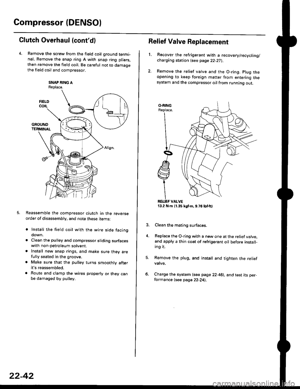
Remove the screw from the field coil ground termi-nal. Remove the snap ring A with snap ring pliers.
then remove the field coil. Be careful not to damaoethe field coil and compressor.
SNAP NING AReplace.
Reassemble the compressor clutch in the reverseorder of disassembly, and note these rrems:
o Install the field coil with the wire side facingdown.
a Clean the pulley and compressor sliding surfaceswith non-petroleum solvent.. Install new snap rings, and make sure thev arefully seated in the groove.
. Make sure that the pulley turns smoothly afterit's reassembled.
. Route and clamp the wires p.operly or they canbe damaged by pulley.
FIELOcorL
22-42
13.2 N.m 11.35 kgt m,9.76lbtttl
Relief Valve Replacement
L
4.
Recover the refrigerant with a recovery/recycling/charging station {see page 22-27),
Remove the relief valve and the O-ring. plug theopening to keep foreign matter from entering thesystem and the compressor oilfrom running out.
Clean the mating surfaces.
Replace the O-ring with a new one at the relief valve.and apply a thin coat of refrigerant oil before install-ing it.
Remove the plug, and install and tighten the reliefvatve.
Charge the system (see page 22-46), and test its per-formance (see page 22-24),
Page 1571 of 2189

-Performance Test
NOTE: Before staning the following checks. disconnect
the wire from terminal M. and make a connection as
described below using as heavy a wire as possible (prefer-
ably equivalent to the wire used for the car).
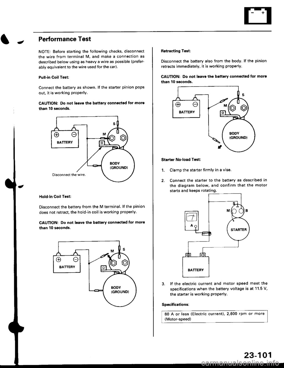
Pull-in CoilTest:
Connect the battery as shown, lf the staner pinion pops
out. it is working proPerly.
CAUTION: Do not leavo tho batterv connost€d for more
than 10 seconds.
Hold-in Coil Test:
Disconnect the battery from the M terminal' lf the pinion
does not retract, the hold-in coil is working properly.
CAUTION: Do not loavc lhe battsry connected for mot6
than 10 ssconds.
Retracting Tosi:
Disconnect the battery also from the body. lf the pinion
retracts immediately, it is working properly.
GAUTION: Do not loave the baftery conn€ctod tor more
than 10 seconds.
Startor No-load Tost:
Clamp the starter firmly in a vise.
Connect the starter to the battery as described in
the diagram below, and confirm that the motor
starts and keeps rotating.
1.
3, lf the electric current and motor speed
specifications when the battery voltage is
the starter is working ProPerly.
Specifications:
80 A or less (Electric current),2,600 rpm or more
(Motor-speed)
meet the
at 11.5 V,
23-101
Page 1579 of 2189

Jlgnition Control Module (lCMl Input Test
NOTE:
. See section 1'l when the malfunction indicator lamp
(MlL) turned on.
. Perform an input test for the ignition control module
(lCM) after finishing the fundamental tests for the
ignition system and the fuel and emissions systems
1. Remove the distributor ignition (Dl) cap, the distrib-
utor ignition (Dl) rotor and the leak cover (TEC).
2. Disconnect the wires from the lCM.
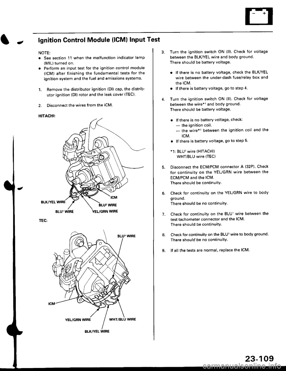
HITACHI:
BLK/YEL
TEC:
Turn the ignition switch ON (ll). Check for voltage
between the BLK/YEL wire and body ground.
There should be battery voltage.
. lf there is no battery voltage, check the BLK/YEL
wire between the under-dash fuse/relay box and
rhe lcM.
. lf there is battery voltage, go to step 4.
Turn the ignition switch ON (ll). Check for voltage
between the wire*r and body ground
There should be battery voltage.
. lfthere is no battery voltage, check:
- the ignition coil.
- the wire*1 between the ignition coil and the
tcM.
. lf there is battery voltage, go to step 5
*1: BLU'�wire (HITACHI)
WHT/BLU wire (TEC)
Disconnect the EcM/PCM connector A (32P). Check
for continuity on the YEUGRN wire between the
ECM/PCM and the lCM.
There should be continuity.
Check for continuity on the YEUGRN wire to body
ground.
There should be no continuity.
Check for continuity on the BLUl wire between the
test tachometer connector and the ICM
There should be continuitY.
Check for continuity on the BLUl wire to body ground.
There should be no continuity.
lf all the tests are normal, replace the ICM
7.
23-109
Page 1606 of 2189
Gauge Assembly
Bulb Locations (With Tachometer)
GAUGE LIGHT II.' WI
SEAT BELTREMINDER LIGHT I1.4 WI
LOW FUELLIGHT 13 W)
RIGHT TURN SIGNALINDICATOR LIGHT I1.4 WI
A/T GEARGAUGE LIGHTS 13 W)
CI{ARGING SYSTEM LIGHT (1.,1W)
GAUGE I-IGHT {1,4 WI
LOW ENGINE OIL PRESSUREINDICATOR LIGHT (1,' W}
HIGH EEAMINDICATOR LIGHT(1.4 W)
GAUGE LIGHT l3.il Wl
MALFUNCTIONINDICATORLAMP {MIL}BULE (1.{ Wl
WASHER I.'C VELINDICATOR LIGHT{1.4 Wl (Canada)
LEFT TURN SIGNALINDICATOR LIGHT {1.4 WI
sRsTOB (1.4 Wl
{On the printed circuit board)INDICATOR (1.12 x 6l(On the printed
circuit board)
ABS |ND|CATOR (1.. Wl{On the printed circuit board)CRUISE or SHIFT-UP INDICATOR 11.12 11.{On the orinted circuit board)
23-136
Page 1607 of 2189
JBulb Locations {Without Tachometer)
TRUNK INDICATORLIGHT {1.i1W}
.4 Wl
CHARGING SYSTEM LIGHT 11,4 W}
LTGHT (1.4 W)GAUGE LIGHT
SEAT BELTREMINDER LIGHT (1.4 WI
LOW ENGINE OIL PRESSUBE
INDICATOB LIGHT (1.4 WI
LOW FUEL INDICATORLrGl{T (3 W)
RIGHT TURN SIGNALINOICATOR LIGHT
(1.1Wt
GAUGE LIGHTS {3 WI
WASHER LEVELINDICATOR LIGHT{1.4 W} lcanad.l
HIGH BEAMINDICATOR LIGHTMALFUNCTIONINDICATORLAMP (MIL)
BULB {1.4 WI
{1.ilW)
LEFT TURN SIGNALINDICATOR LIGHT {1.4 WI
A/T GEAR POSITIONINDICATOR (1.12 x 6)(On the printed
circuit board)
sRs TND|CATOR 11.4 W)
{On the Drinted circuit board}
aBs tNDtcAToR t1.4 W)(On the printed circuit board)(3.{ Wt
o/ o \7 o
23-137
Page 1625 of 2189

A/T Gear Position Switch
Replacement
1.
2.
7.
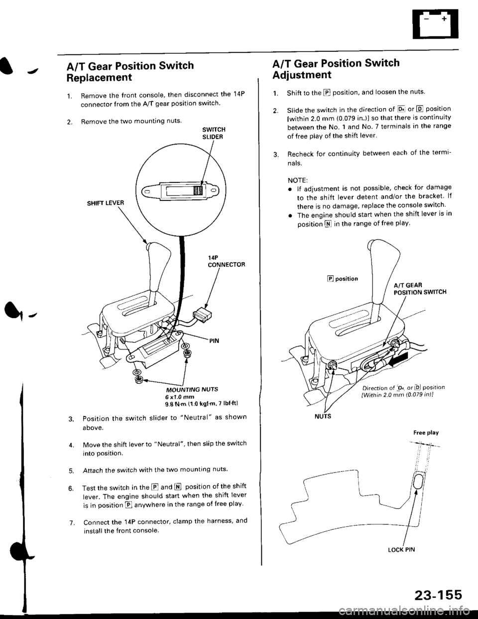
Remove the front console, then disconnect the
connector from the A/f gear position swltch
Remove the two mounting nuts
swrTcHSLIDEB
MOUNT'NG NUTS6x1 0mm98Nm(10kgtm'7lblftl
Position the switch slider to "Neutral" as shown
above.
Move the shift lever to "Neutral", then slip the switch
into position.
Aftach the swjtch with the two mounting nuts.
Test the switch in the E and E position ofthe shift
lever. The engine should start when the shift lever
is in position fl anywhere in the range of free play
Connect the 14P connector, clamp the harness, and
install the front console
14P
A/T Gear Position Switch
Adjustment
1.
3.
Shift to the E position, and loosen the nuts.
slide the switch in the direction of El or E position
lwithin 2.0 mm (0.079 in.)l so that there is continuity
between the No. 1 and No 7 terminals in the range
of free play of the shift lever'
Recheck for continuity between each of the termi-
nats.
NOTE:
. lf adjustment is not possible, check for damage
to the shift lever detent and/or the bracket lf
there is no damage. replace the console switch
. The engine should start when the shift lever is in
position N in the range of free play
E positionA/T GEARPOSITION SWITCH
Djrection of -on, or Dl Positionlwithin 2.0 mm (0.079 in)1
Free play
-lfr-
LOCK PIN
23-155