1998 HONDA CIVIC ecu reset
[x] Cancel search: ecu resetPage 157 of 2189

Cylinder Head
Installation (cont'dl
Position the camshaft correctly (see page 6-20).
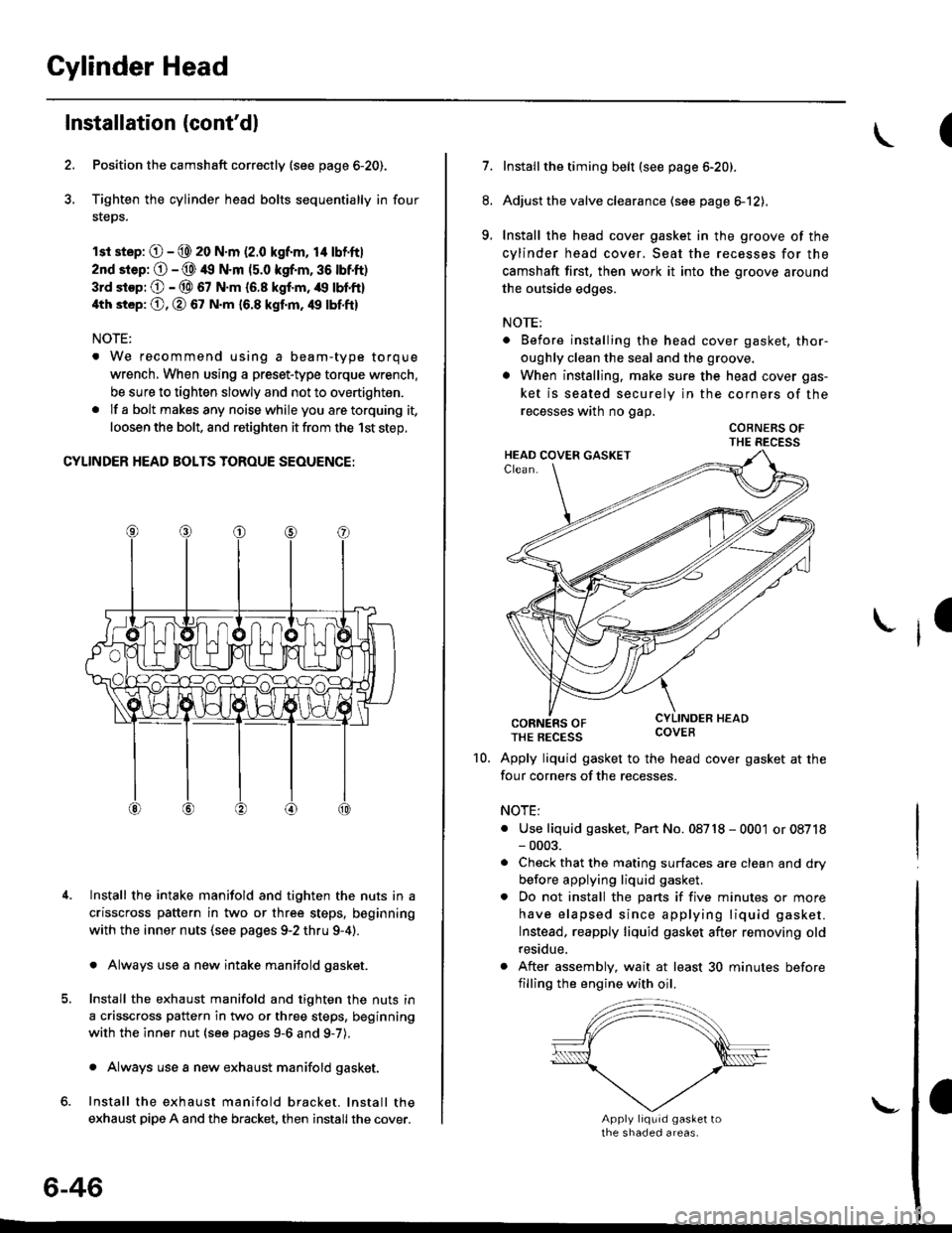
Tighten the cylinder head bolts sequentially in four
steps.
rsr st.p: O - @ 20 N.m (2.0 kgf.m, 14 lbf'ft|
2nd srep: O - @ 49 N.m (5.0 kgf.m, 36 tbtft)
3rd stop; O - @ 67 N.m {6.8 kgf.m, /r9 lbl'ft}
4th st6p: O, O 67 N.m 16.8 kgf.m, 49 tbf.ftl
NOTE:
. We recommend using a beam-type torque
wrench, When using a preset-type torque wrench.
be sure to tighten slowly and not to overtighten.
. If a bolt makesany noisewhileyou aretorquing it,
loosen the bolt, and retighten it from the 1st step,
CYLINDER HEAD BOLTS TOROUE SEOUENCE:
Install the intake manifold and tighten the nuts in a
crisscross pattern in two or three steps, beginning
with the inner nuts (see pages 9-2 thru 9-4).
. Always use a new intake manifold gasket.
Install the exhaust manifold and tighten the nuts in
a crisscross pattern in two or three steps, beginning
with the inner nut {see pages 9-6 and g-7).
. Always use a new exhaust manifold gasket.
Install the exhaust manifold bracket. lnstall the
exhaust pipe A and the bracket, then install the cover.
4.
6-46
\-
(
7.Installthe timing belt (see page 6-20).
Adjust the valve clearance (see page el2),
Install the head cover gasket in the groove of the
cylinder head cover, Seat the recesses for the
camshaft first, then work it into the groove around
the outside edges.
NOTE:
. Before installing the head cover gasket, thor-
oughly clean the seal and the groove.
. When installing, make sure the head cover gas-
ket is seated securely in the corners of the
recesses wath no gap.
COBNERS OFTHE RECESS
CORNERS OFTHE REcEss covEB
Apply liquid gasket to the head cover gasket at the
four corners of the recesses.
NOTE:
. Use liquid gasket, Pan No. 08718 - 0001 or 08718- 0003.
. Check that the mating surfaces are clean and dry
before applying liquid gasket.
. Do not install the parts if five minutes or more
have elapsed since applying liquid gasket.
Instead, reapply liquid gasket after removing old
residue.
. After assembly, wait at least 30 minutes before
filling the engine with oil.
8.
9.
I
10.
Page 414 of 2189

Primary Heated Oxygen Sensor (Primary HO2S) (Sensor 1l
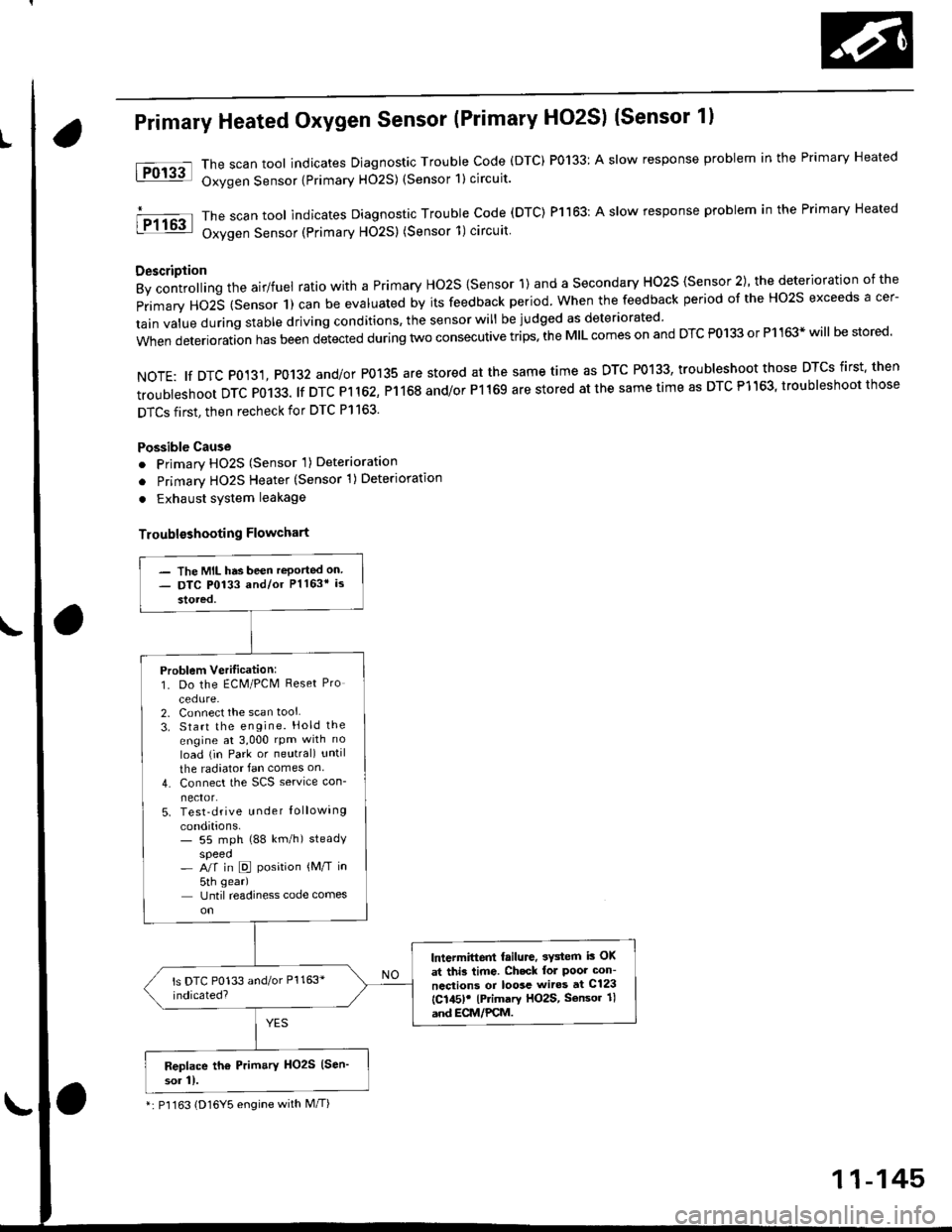
The scan tool indicates Diagnostic Trouble Code (DTC) P0133: A slow response problem in the Primary Heated
Oxygen Sensor {Primary H02S) (Sensor 1) circuit.
The scan tool indicates Diagnostic Trouble code (DTC) Pl163: A slow response problem in the Primary Heated
Oxygen Sensor (Primary HO2S) (Sensor 1)circuit
Description
By controlling the airlfuel ratio with a Primary Ho2S {Sensor 1) and a secondary HO2S {Sensor 2), the deterioration of the
primary HO2S (Sensor 1) can be evaluated by its feedback period. when the feedback period of the Ho2s exceeds a cer-
tain value during stable driving conditions, the sensor will be judged as deteriorated
when deterioration has been detected during two consecutive trips. the MIL comes on and DTC P0133 or P1163* will be stored'
NOTE: tf DTC P0131, P0132 and/or P0135 are stored at the same time as DTC P0133, troubleshoot those DTCS first' then
troubleshoot DTC P0133. lf DTC Pl 162, P1168 and/or P1169 are stored at the same time as DTC P1163, troubleshoot those
DTCS first, then recheck for DTC Pl163.
Possible Cause
o Primary HO2S (Sensor 'l) Deterioration
o Primary HO2S Heater (Sensor 1)Deterioration
. Exhaust system leakage
Troublsshooting Flowchart
tFol3al
I P1163
- The MIL has been reported on- DTC P0133 and/or Pl163* is
stored,
Problem Verilication:1. Do the ECM/PCM Reset Pro
cedure-2. Connect the scan tool
3. Start the engine. Hold the
engine at 3,000 rpm with no
load (in Park or neutral) until
the radiator fan comes on
4. Connect the SCS service con-
nector.5. Test-drive u nder Iollowing
conditions.- 55 mph (88 km/h) steadyspeed- A/f in D position {M/T in
5th gear)
Until readiness code comes
lntermittent failure, 3Y3tem i3 OK
at thi3 time. Ch.ck lol Poor con-
ncctions or loosc wiros at C123
{C145)! lPrimary HO2S, Sensor 1l
and ECM/PCM.
Replace th6 Prim.ry HO2S (Sen'
sor 11.
*: P'l163 (D16Y5 engine with M/T)
11-145
Page 522 of 2189

\
lTo420l Th" """n toot indicates Diagnostic Troubte code (DTc) p0420: catatyst sysrem efficiency below threshold.
Description
This system evaluates the catalyst's capacity by means of the Ho2s {Primary and secondary) output during stable driving
conditions. ll deterioration has been detected during two consecutive driving cycles. the MIL comes on and DTC P0420 will
be stored.
NOTE: lf some of the DTCS tisted below are stored at the same time as DTC P0420, troubleshoot those DTCS first. then
recheck for DTC P0420
P0137, P0138: Secondary HO2S (Sensor 2)
Po14'1:Secondary H02S {Sensor 2) Heater
Possibl€ Cause
. TWC Deterioration
. Exhaust system leakage
Troubleshooting Flowchart
I
The MIL has been reported on.
DTC P0420 is stored
Problem verilication:1. Do the ECM/PCM Reset Proce
dure.2. Start the engine Hold the
engine at 3,000 rpm wath no
load {in Park or neutral) until
the radiator fan comes on.
3. Connect the SCS service con
4. Test drive 40 - 55 mph for
approx, two minutes Then
decelerate for at least 3 sec_
onds with the throttle com'pletely closed- Then reduce
the vehicle speed to 35 mph,
and try to hold it until the
readiness code comes on
Intermittent Iailure, system is OK
at this time.ls DTC P0420 indicated?
Check the TWC {see section 9l
lf necessary, replace the TwC
Page 1560 of 2189

lgnition Switch
Steering Lock Replacement
SRS components are located in this area. Review theSRS component locations. precautions, and procedures
in the SRS section (24) before performing repairs or ser-vtce.
Remove:
LMake sure you have the anti-theft code for theradio, then wire down the frequencies for theradio's preset buttons ('99 - 00 models).
Disconnect the battery negative cable.
Remove the driver's dashboard lower cover andknee bolster (see section 20).
Disconnect the 5P connector from the under-dash
fuse/relay box and the 7P connector from the mainwire harness (see previous page).
Remove the steering column covers, then removethe mounting bolts and nuts from the steering col-umn (see section l7).
Lower the steering column assembly,
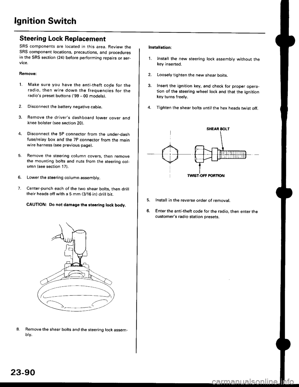
Center-punch each of the two shear bolts, then drilltheir heads off with a 5 mm (3/16 in) dritt bit.
CAUTION: Do not damago the steering lock body.
Remove the shear bolts and the steering lock assem,oty.
2.
1.
23-90
Installation:
l. Install the new steering lock assembly without thekey insened.
Loosely tighten the new shear bolts-
Insert the ignition key, and check for proper opera-tion of the steering wheel lock and that the ignitionkey turns freely.
Tighten the shear bolts untilthe hex heads twist off.
TWIST.OFF FORTION
Install in the reverse order of removar.
Enter the anti-theft code for the radio, then enter thecustomer's radio station presets.
sr{€aR SroLT
Page 1590 of 2189

Charging System
Alternator Replacement
NOTE: Remove the alternator from below the vehicle.
'1. Make sure you have the anti-theft code for theradio, then write down the frequencies for theradio's preset buttons ('99 - 00 models).
2. Remove the battery negative cable, then disconnectthe positive cable.
3. Disconnect the 4P (or 3P) connector from the alter-naIor.
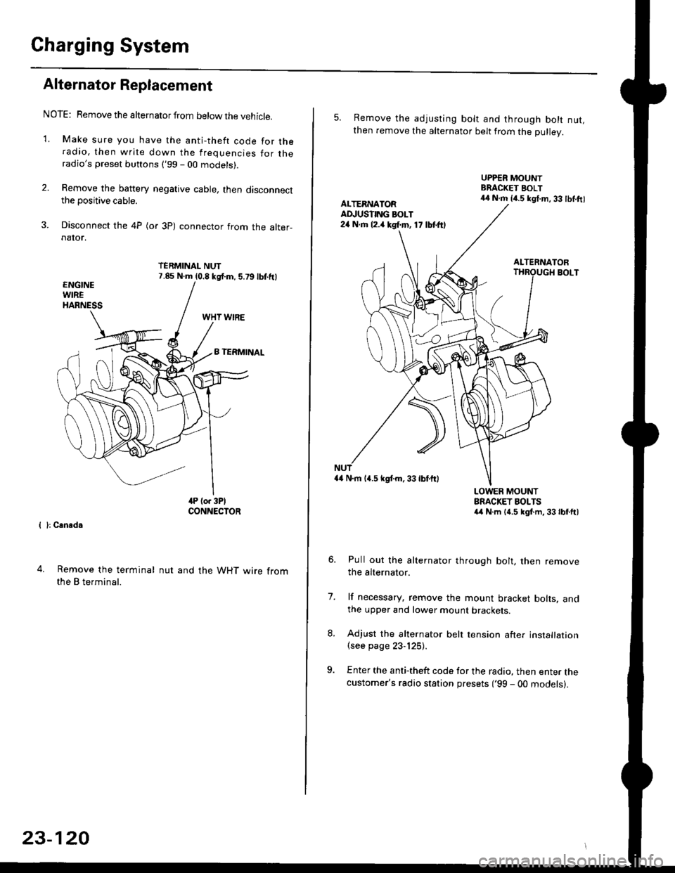
TERMINAL NUT7.85 N.m (0.8 kgf.m, 5.79lbf.ftl
{ }: Cansd.
4. Remove the terminal
the B terminal.
nut and the WHT wire from
23-120
5. Remove the adjusting bolt and through bolt nut,then remove the alternator belt from the Dullev.
UPPER MOUNTBRACKET BOLT44 N.m 14.5 kgt.m, 33 lbl.ftlALTERNATORAD.'USTING BOLT24 N.rh l2.a kgf.m, 17 lbtft)
ALTERNATORBOLT
a4 N.m 14.5 kstm.33lbf'ftl
LOWER MOUNTBRACKET BOLTSa4 N.m l{.5 kgf.m,33lbfft)
Pull out the alternator through bolt, then removethe alternator.
lf necessary, remove the mount bracket bolts. andthe upper and lower mount brackets
Adjust the alternator belt tension after installation(see page 23-125).
Enter the anti-theft code for the radio, then enter thecustomer's radio station presets ('99 - 00 models).
7.