Page 112 of 2189

Cylinder Head/Valve Train
Dl6Y5, D16Y7, Dl6Y8 engines
Special Tools ............. G2
VTEC Control System
Troubleshooting Flowchart .........." 6-3
VTEG Solenoid Valve
Inspection ............" 6-6
VTEC Rocker Arms
Manual lnspection
(D16Y5 engine) ............................. 6-7
Manual Inspection
(D16Yg enginel ................'............ 6-7
Inspection Using Special Tools
{D16Y5 engine} .....................""'... 6-8
Inspection Using Special Tools
(D16Y8 engine) .........................'.'. 6-10
Valve Clearance
Adiustment ..."".....6-12
Valve Seals
Replacement (Cylinder head removal
not requiredl ................................ 6-1tl
Crankshaft Pulley and PulleY Bolt
Replacement ."...... &16
Timing Selt
lllustrated Index ............................... 6-17
Inspection .............. 6-18
Tension Adjustment ........................ 6- 1 I
Removal ......,,......... 6-19
lnstallation ............. 6-20
Crankshaft Speed Fluctuation (CKF) Sensor
Repf acement .........6'22
Cylinder Head
lllustrated Index ............................... 6-23
Removal ................. 6-27
Warpage ................ 6-40
lnstallation ............. 6-45
Rocker Arms
Removal ................. 6-30
Disassembly/Reassambly ............... 6-31
Rocker Arms and Lost Motion Assemblies
Inspection (D16Y5, D16Yg
enginesl "..........' 5-34
Rocker Arms and Shafts
Glearance Inspection ....................... 6-35
Camshaft
Inspection .............. 6-36
Valves, Valve Springs and Valve Seals
Removal ........""..... 6-38
Valve Guides
Valve Movement .............................. 6-39
Replacement .........6-41
Reaming .......'......'.' 6-43
Valve Seats
Reconditioning .'....6'40
Valves
lnstallation ............. 6-tt3
Camshaft/Rocker Arms and
Camshaft Seal/Pulley
lnstallation ............. 6-44
Page 123 of 2189

Valve Clearance
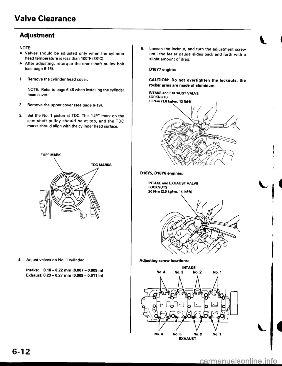
Adjustment
NOTE:
. Valves should be adjusted only when the cylindsrhead temperature is less than 100"F (38"C).
. After adjusting, retorque the crankshaft pulley bolt(see page 6-16).
1, Remove the cylinder head cover.
NOTE; Refer to page e46 when installing the cytinderhead cover.
2. Remove the upper cover (see page 6-19).
3. Set the No. 1 piston at TDC. The "UP" mark on the
cam-shaft pulley should be at top, and the TDC
marks should align with the cylinder head surface.
TDC MARKS
4. Adjust valves on No, 1 cylinder.
Intako: 0.18 - 0.22 mm {0.007 - 0.009 in}
Exhaust: 0.23 - 0.27 mm (0.009 - 0.011 inl
"UP" MARK
6-12
No.4
5. Loosen the locknut, and turn the adjustment screwuntil the feeler gauge slides back and forth with asliOht amount of drag,
D16Y7 engin.:
CAUTION: Do not oyertighlen the locknuts; thorockor arms are made of aluminum.
INTAKE end EXHAUST VALVELOCKNUTS
Dl6Y5, Dl6Y8 engin€3:
INTAKE .nd EXHAUST VALVELOCKNUTS20 N.m 12.0 kstm, 14lbtft)
Adiusting screw locations:
IMTAKEo.4 1{o. 3 No. 2
tr'
(
nb.3 No.2 No. 1EXHAUST
18 N.m (1.8 kgI.m, 13 tbl.ftl
Page 127 of 2189
Crankshaft Pulley and Pulley Bolt
Replacement
When installing and tightening the pulley. follow theprocedure below,
Clean, remove any oil, and lubricate points shown
below.
O: Clean
x: Bemove any oil
a: Lubricate
TIMING BELTGUIOE PLATE
Crankhaft pulley bolt size and torque value:
14 x 1.25 mm
20 N.m {2.0 kgl.m, 14 lbf.ft) + 90'
NOTE: Do not use an impact wrench when installing.
HOI.I'ER HANDTI07JAB - 001020A
HOLDER ATTACHMENT. 50 mm07NAB - ootoilllA
S(rc(ET, 17 mm07JAA-lxtl010A or{Co.nm.rci.lly .v.il.bl.}
CRANKSHAFT
6-16
'1.Tighten the pulley bolt to the specified torque.
Torque: 20 N.m {2.0 kgf.m, 14 lbf'ft}
Use I felt tip pen to mark the pulley bolt head andwasher.
EMBOSSING MARKS
3. Tighten the pulley bolt an additional 90".
EMBOSSING MABKMARKING
\
MARKING
MARKING
I
Page 128 of 2189

Timing Belt
Illustrated lndex
NOTE:
. Refer to page 6-20 for how to position the crankshaft and pulley before installing the belt.
. Mark the direction of rotation on the belt before removing.
a Do not use the upper cover and lower cover for storing removed items,
. Clean the upper cover and lower cover before installing.
. Replace the ca mshaft seals and cra n kshaft sea ls if there is oil leakage.
. Refer to page 6-16 before installing the timing belt.
CYLINDER HEADCOVERReler to page 6-46when installing.
HEAD COVEB GASKETReplaco when l6akin9,domaged or deteriorated.Apply liquid gasket at
th€ lour corners of thetecessos.
d
@
TIMING BELTInspection, page 6-18Adjustment, page 6-18Removal, page 6-19Installation. page 6-20
I x 1.25 mm3t N.m {3.8 kgf'm, 27 lbfftl
Apply engine oilto the bolt
thleads.
CRANKSHAFT SPEED FI.UCTUATION
lcr(Fl sENsoRReplacement, Page 6-22
UPPER COVEB
lnstallwithsurface facing in.
TIMING BELTDRIVE PULLEYReplacement, page 6_16
6x1.0mm9.8 N'm 11.0 kgt m,7.2 tbf.ft)NUBBER SEALSReplace when damagedor deledorated.
LOWER COVER
FUBBERPLUG
CRANKSHAFT PULLEYReplacement, page 6'16
PULLEY BOLTlil x 1.25 mm20 N.m 12.0 kgt.m,14 lbt'ft) + 90"Replacement, page 6'16Do not us6 an impactwrench when installing.
x 1.0 mmBOLT o-RING10 x 1,25 mm Reolace.14 N.m {,1.5 kgt m, 33 lbt ftl
6x1.0mmt2 N.m 11.2 kgf'm,8.7 tbt f0
9.E N'm (1.0 kgt.m,?.2 tbf.ftl\.-,o
6-17
Page 129 of 2189

Timing Belt
Inspection
1.
2.
3.
Remove the cylinder head cover.
. Refer to page 6 46 when installing.
Remove the upper cover (see page 6 19).
Inspect the timing belt for cracks and oil or coolantsoakrng.
NOTE:
. Replace the belt if oil or coolant soaKeo.. Remove any oil or solvent that gets on the belt.
Rotate pulleyand inspect belt.
After inspecting, retorque the crankshaft pullev bolt{see page 6- 16).
o- I6
Tension Adjustment
CAUTION: lt*ays aa;j"t the timing bett rension withthe engine cold.
NOTE:
. The tensioner is spring loaded to apply tension to thebelt automatically after making the following adjustment.
. Always rotate the crankshaft counterclockwise whenviewed from the pulley side. Rotating it clockwisemay result in improper adjustment of the belt ten-sion.
. lnspect the timing belt before adjusting the belt ten-ston.
1.Remove the cylinder head cover.
. Refer to page 6,46 when installing.
Remove the upper cover (see page 6,'19).
Rotate the crankshaft five or six revolutions to setthe belt.
Set the No. 'l piston at TDC (see page 6-21).
Loosen the adjusting bolt 180'.
2.
3.
4.
5.
\I
ADJUSTING BOLT44 N.m {4.5 kgt m,33 rbf.ft)
7.
8.
Rotate the crankshaft counterclockwise three teethon the camshaft pulley.
Tighten the adjusting bolt.
After inspecting, retorque the crankshaft pulley bolt(see page 6-16).
Page 130 of 2189

Removal
NOTE:
. Replace the timing belt at 105,000 miles (168.000 km)
according to the maintenance schedule (normal con-
ditions/severe conditions).
lf the vehicle is regularly driven in one or more of the
followlng conditions, replace the timing belt at 60.000
miles (U.S.A.) 100,000 km {Canada).
.In very high temperatures (over 110'F.43'C)
. In very low temperatures (under -20'F, -29"C)'
! Turn the crankshaft pulley so the No. 1 piston is at
top dead center (TDC) before removing the belt (see
page 6'21).
. Inspect the water pump before installing the timing
belt {see Page 10-14).
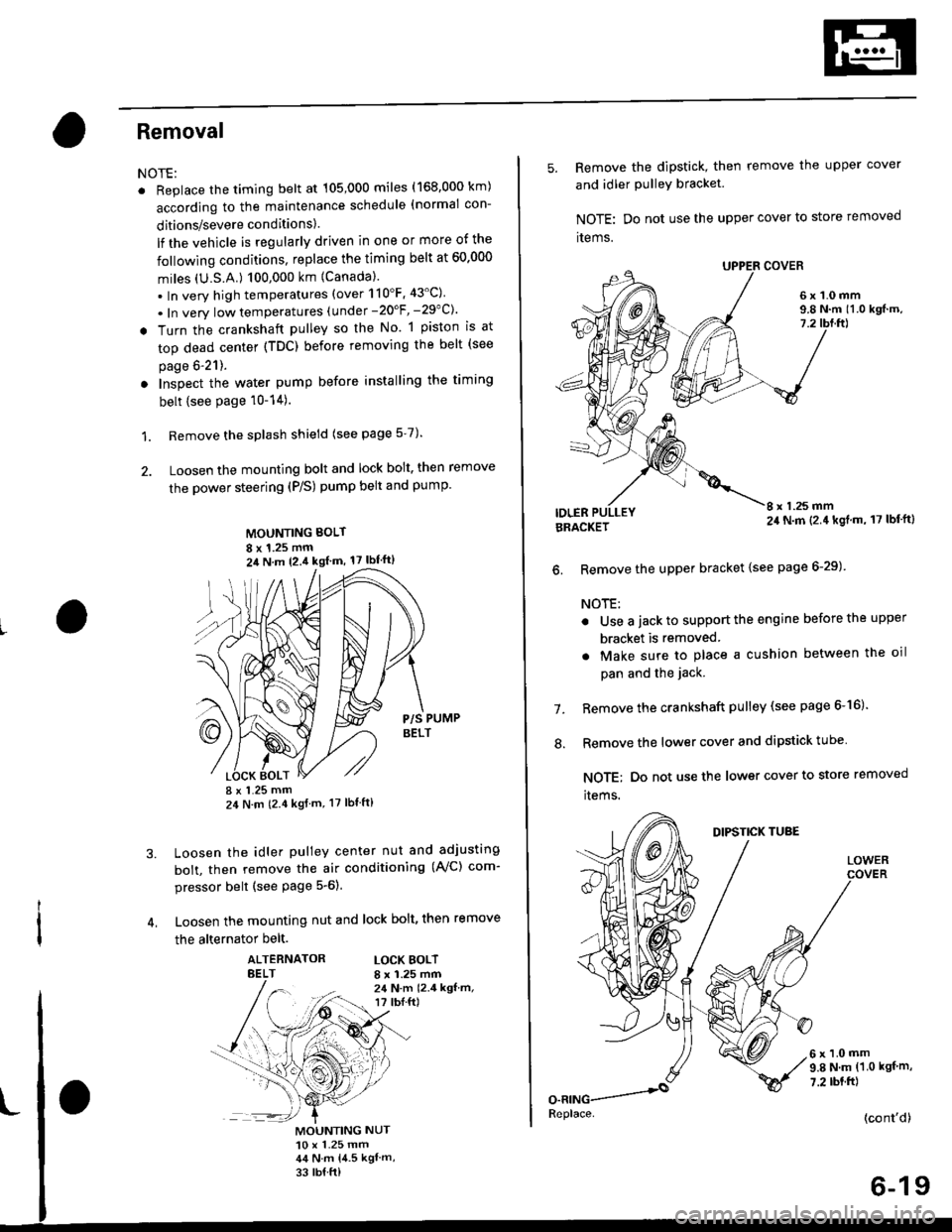
1. Remove the splash shield (see page 5-7).
2. Loosen the mounting bolt and lock bolt. then remove
the power steering (P/S) pump belt and pump
MOUNTING BOLT
8 x 1.25 mm2il N m 12.4 kgl m, 17 lbf'ft)
P/S PUMPBELT
I x 1.25 mm24 N m (2.4 kgf m, 17 lbt ft)
Loosen the idler pulley center nut and adjusting
bolt, then remove the air conditioning (AVC) com-
pressor belt (see Page 5-6).
Loosen the mounting nut and lock bolt, then remove
the alternator belt.
ALTERNATORBELTLOCK BOLTI x 1.25 mm24 N.m 12.4 kgf.m,r? tbI.ft)
3.
MOUNTING NUT10 x 1.25 mm44 N.m 14.5 kgl m,
33 rb{ ft)
5. Remove the dipstick, then remove the upper cover
and idler PulleY bracket
NOTE: Do not use the upper cover to store removed
items.
6x1.0mm9.8 N.m 11.0 kgf.m,7.2
IDLERI x 1.25 mm24 N.m (2.4 kgl.m, 17 lbf'ft)BRACKET
6. Remove the upper bracket {see page 6-29)
NOTE:
. Use a jack to support the engine before the upper
bracket is removed
. Make sure to place a cushion between the oil
pan and the jack.
Remove the crankshaft pulley (see page 6-16).
Remove the lower cover and dipstick tube
NOTE; Do not use the lower cover to store removed
items.
1.
.'.
DIPSTICK TUBE
LOWER
6x1.0mm9.8 N.m (1.0 kgf m,
7.2 rbt.ft)
(cont'd)
6-19
Replace.
Page 132 of 2189

3. Install the timing belt tightly in the sequence shown'
OTiming belt drive pullev (crankshaft) )@Adjusting
pulley -towater pump pulley J@Camshatt pulley'
NOTE: Make sure the timing belt drive pulley and
camshaft PulleY are at TDC
7.
Loosen and retighten the adiusting bolt to tension
the timing belt.
lnstall the lower cover and upper cover.
NOTE: Clean the upper and lower covers before
installation.
lnstall the crankshaft pulley, then tighten the pulley
bolt (see page &16)
Rotate the crankshaft pulley about five or six turns
counterclockwise so that the timing belt positions
on the Pulleys.
Adjust the timing belt tension (see page 6-18).8.
L
9. Check that the crankshaft pulley and camshaft pul-
ley are both at TDC.
CRANKSHAFT PULLEY:
CAMSHAFT PULLEY:
lf the camshaft and crankshaft pulleys are not posi-
tioned at TDC, remove the timing belt and adjust
the position following the procedure on page 6-20'
Then reinstall the timing belt.
After installation, adjust the tension of each belt
. See section 23 for alternator belt tension adjust-
ment.
a See section 22 tot NC compressor belt tension
adjustment.
. See section 17 for P/S pump belt tension adjust
ment,
(wHrTE)
"UP" MARK
TDC MARK
11.
6-21
Page 133 of 2189
Crankshaft Speed Fluctuation (CKF) Sensor
2.
3.
5.
Replacement
4.
1.
6x1.0mm'12 N.m {1.2 kgt.m,8.7 tbf.ft)
6. Installthe CKF sensor in reverse order of removal.
Remove the cylinder head cover.
NOTE: Refer to page 6-46 when installing.
Remove the crankshaft pulley (see page 6_16),
Remove the upper cover and dipstick/tube {seepage 6-19).
Remove the lower cover and idler pulley bracket(see page 6-19).
Disconnect the CKF sensor connector, then removethe CKF sensor.
CKF SENSORCONNECTOR
6-22
:(
I