Page 1535 of 2189

lr-
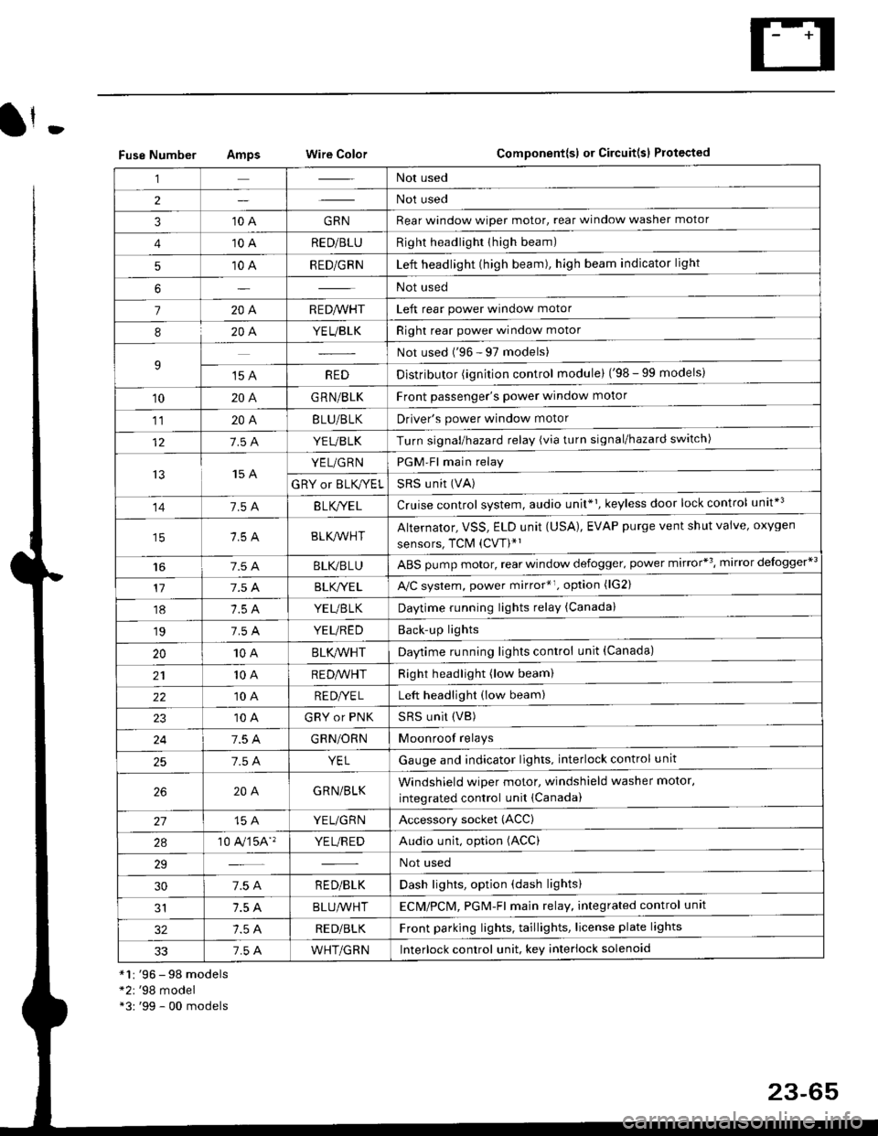
Fuse NumberAmpswire ColorComponent{sl or Circuit(sl Protected
*1r '96 - 98 models*2r '98 model*3: '99 - 00 models
,lNot used
2Not used
310 AGRNRear window wioer motor, rear window washer motor
410 ARED/BLURight headlighr thigh beam)
510 ARED/GRNLeft headlight (high beam), high beam indicator light
6Not used
7204R E D/VVHTLeft rear power window motor
820A.YEUBLKRight rear power window motor
9Not used ('96 - 97 models)
't5 AREDDistributor (ignition control module) ('98 - 99 models)
10204G RN/BLKFront passenger's power window motor
1120ABLU/BLKDriver's power window motor
127.5 AYEUBLKTurn signal/hazard relay (via turn signal/hazard switch)
t515 AYEL/GRNPGM-Fl main relay
GRY or BLK,^/ELSRS u nit (VA)
141.54B LK/YE LCruise control system, audio unit*1, keyless door lock control unit*3
BLK/lr'r'HTAlternator, VSS, ELD unit (USA), EVAP purge vent shut valve, oxygen
sensors, TCM (CVT)*'
t6BLI(,/BLUABS pump motor, rear window defogger. power mirror*3, mirror delogger*3
177.5 ABLK,/YE LA,/C system, power mirror*r. option (lG2)
18YEUBTKDaytime running lights relay (Canada)
197.5 AYEUREDBack'up lights
2010ABLK/VVHTDaytime running lights control unit (Canada)
2110 AREDA/VHTRight headlight (low beam)
2210 ARE DI/E LLeft headlight (low beam)
10 AGRY or PNKSRS UNit (VB)
247.5 AGRN/ORNMoonroof relays
257.5 AYELGauge and indicator lights. interlock control unit
204GRN/BLKWindshield wiper motor, windshield washer motor,
integrated control unit {Canada)
15 AYEL/GRNAccessory socket (ACC)
2a10 A,/'�]5A''YE L/R EDAudio unit, option (ACC)
29Not used
307.5 AR ED/BLKDash lights, option (dash lights)
1.5 ABLUA/VHTECM/PCl\4, PGM-Fl majn relay, integrated control unit
RED/BLKFront parking lights, taillights, license plate lights
337.5 AWHT/GRNlnterlock control unit. key interlock solenoid
23-65
Page 1543 of 2189
!t
USA:
UNDER,DASH FUSEi RELAY BOX
COMEINATONLIGHT SWITCH
No.48 (304)FUSE/Frcm page \\23{8 /
No.a8 G0A)FUSE/Frcm page \\23-72 )
lo
I ' to"'to
RED/BLU _
BED/GRN _
FEO/GRN -
REDMHT -
REo/{EL -
Figltl h6adlighl (High beam)
High beam indi€tor light
Lefl headlighl (High beam)
Right headlighl (Low beam)
Letl headlighl (Low beam)
(Fuse/relay box socl(el)
(Fuss/relay box sockel)
FEo/BLK t
RED/BLK t
optioml @nn6clor loash hghls)
InEgraled control unil
Hazard waming sMch ligldGaugelighlsAudio unilnear wndow delog0er swild lighlCruiso main switdr lighlctuis€ndrcalot .. ]crmminocircu,tA/ | qsar posrrcn nor@Ior JDash lighls brighhess mnlroller
l'/T gea. pGilion console lighlHeald conlrol panel ligtn
::: I lronl oarkino liohlHqm,
n-'i6 J *t"' t"itt'9t'6
n-,sh j inn"t u'll'gl't'
:: 1 | hcense Dlale liohtsHgnr i
(cont'd)
23-73
Page 1544 of 2189

Power Distribution
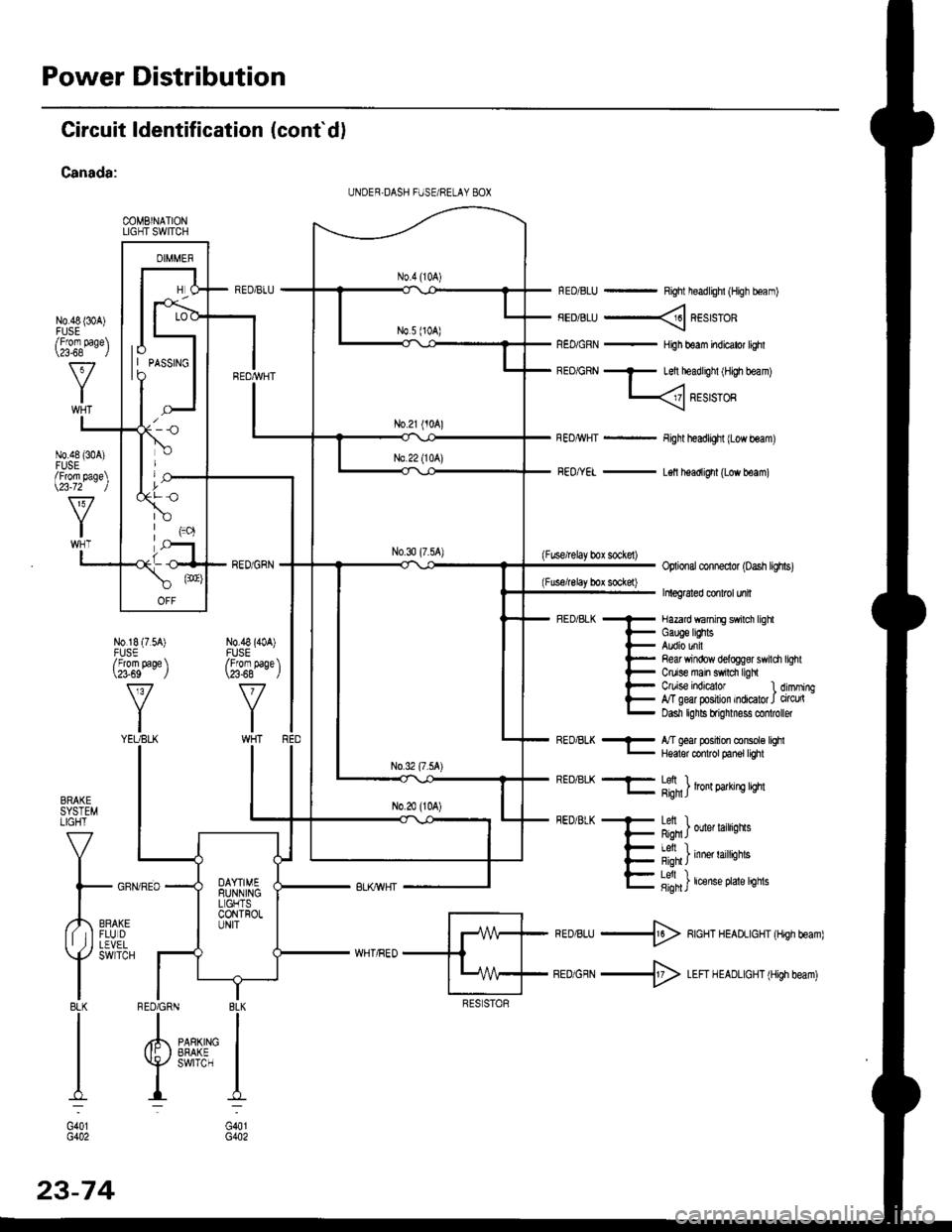
Circuit ldentification (cont'd)
Canada:
COMBINATIONLIGHT SWITCH
N0.48 {30A)
RED/BLU - Right headlighl (High boam)
FEDiBLU ----< REstsTOR
REo/GRN - HiJh beam indicator lighl
BEo/GRN - Left headlighl iH,gh beam)
L
Fight headlight {Low beam)
FEo/YEL - L€ll headlight (Low beam)
(Fuse/lelay box sockel)Optional conneclor (oash lighs)
Inleg6led conlrcl unil
- Hazard wanirE swilch lighl
i- Gauge lEhts
l- Audio unil
l- Re& Yrindow delogg8r swili
t- Ctuise main swrdr ligh
l- C/uise indEator l
E g"ffiry:'l,:1':::1
Refi window delog$r swildr light
Ctuise indicalor 1 dimming,T geal posilion indicator J circu(Dasn lghls brignmess co oller
BRAKESYSTEMLIGHT
V
I
l- GFf
,,4,,0*,lf tIFLUDII ,j I LEVEL
Y
SWTCH
I8LKI
I
I
I:
G401G402
REo/BLK - l/T ged position console lqhl- Hqalor codrot panel tighl
REO/BLK -F- Lefi ) .l- g;n1J lron 9arrn! qm
FEDiBLK + Letl I
F Rqn J ouer larrqns
- I Al, I
{- i'-;*; inne' raittiotts
E fifi]t'"nt"o't't'sn"
*ro,rru -$ RcHT HEADLIGHT (Hrgh beam)
BEDiGRN -+ LEFI H EADLIGHT (High beam)
I BLK
IIPARKING IEFAKE IswrrcH I
I:
G401G402
UNDER,DASH FUSE/RELAY 8OX
lo| | PASSTNGto
/Fforn page\\a-68 l
N0.48 {304)FUSE/From page\\23-72 )
N0.18 (7.54)FUSE/From page \\?3-69 J
v
YIYEUBLK
N0.48 (40A)FUSE/From paqe \\23-68 - ,/
RED6RN
23-74
Page 1586 of 2189

Charging System
Troubleshooting (cont'd)
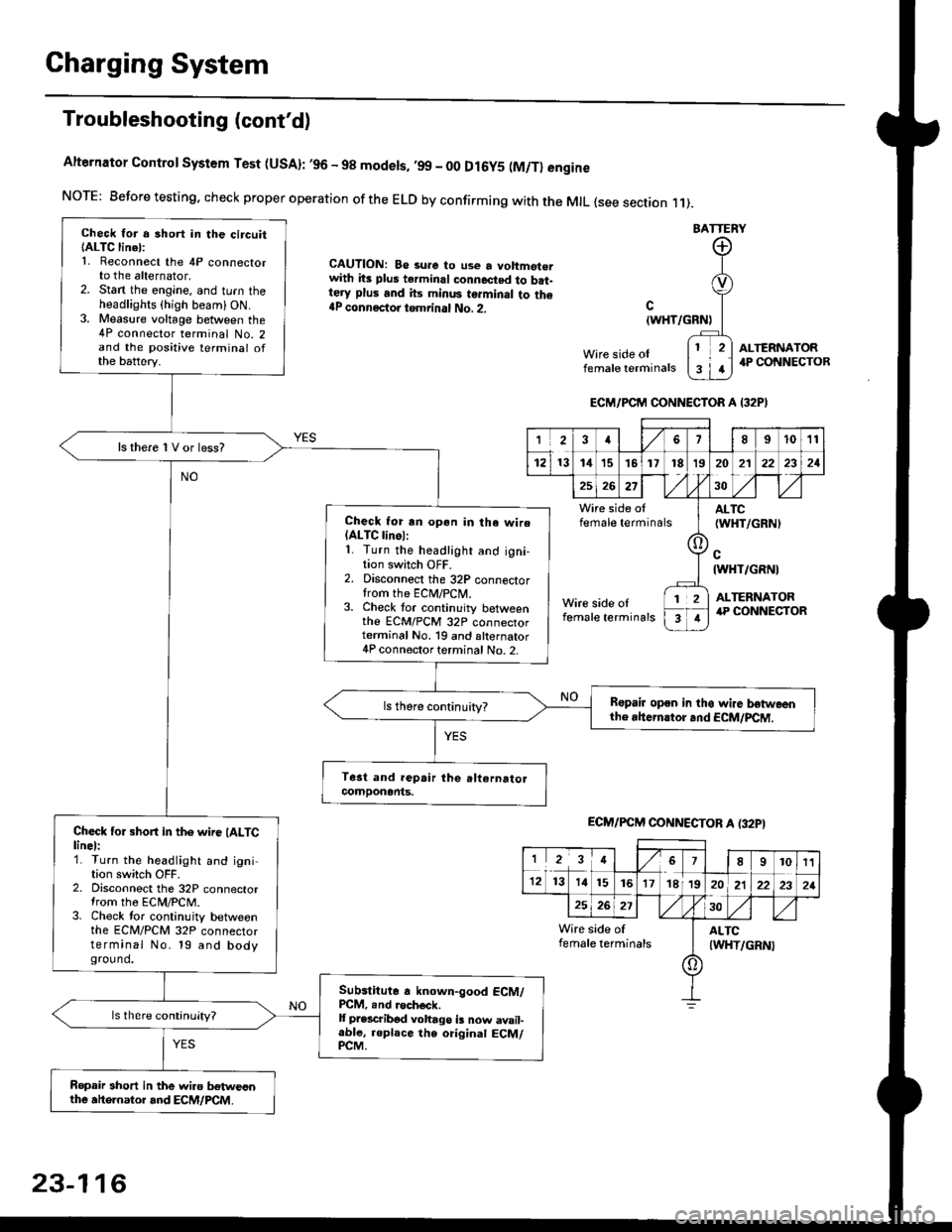
Alternator Control System Test (USA): ,96 - 98 modets, ,99 _ 00 Dl6y5 (M/Tl engine
NorE: Before testing. check proper operation of the ELD by confirming with the MrL {see section r 1).
BATTERY
CAUTION: Be 3ure to use a voltmot€.with its plus terminal connected to b.t-tery plus and its minus terminal to the{P connectoi tgmrinal No. 2.c
{WHT/GRNt
Wire side oIfemale terminals
ALTERNATOR.P CONNECTOB
Check for a 3hort in the circuitIALTC linel:1. Reconnect the 4P connectorto the alternator,2. Stan the engine, and turn theheadlights {high beam) ON.3. Measure voltage between the4P connector terminal No. 2and the positive terminal ofthe battery.
ls there 1V or less?
Check for rn opon in tha wire(ALTC linol:1. Turn the headlight and igni-tion switch OFF.2. Disconnect the 32P connectortrom the ECM/PCN4.3. Check tor continuity betweenthe ECM/PCM 32P connectorterminal No. 19 and alternator4P connector terminal No. 2.
Bspair open in thg wire lrstweenthe rhern.tor .nd ECM/PCM.
Check for short in the wire (ALTClinel:1. Turn the headlight and ignition switch OFF.2. Disconnect the 32P connectortrom the ECM/PCM.3. Check tor continuity betweenthe ECM/PCM 32P connectorterminal No. 19 and bodyground.
Subslitute a known-good ECM/PCM, .nd .och6ck.It p.escribod vohago i! now avail-able, replace the original ECM/PCM.
Ropair 3hort in the wiro betweonthe ahe.nator and ECM/PCM.
ECM/PCM CONNECTOR A I32PI
'Ia18I1011
121314151718t9
7
202'l2221
262730
Wire side offemale terminalsALTC(WHT/GRNI
c{WHT/GRNI
ALTERNATORWire side oIfemale terminals
([l
T
12
1
ECM/PCM CONNECTOB A (32PI
I23478910t1
1213 14151617182021222321
262730
Wire side of I AITCfemate terminats
A
(WHT/GRN|
23-116
Page 1587 of 2189

-
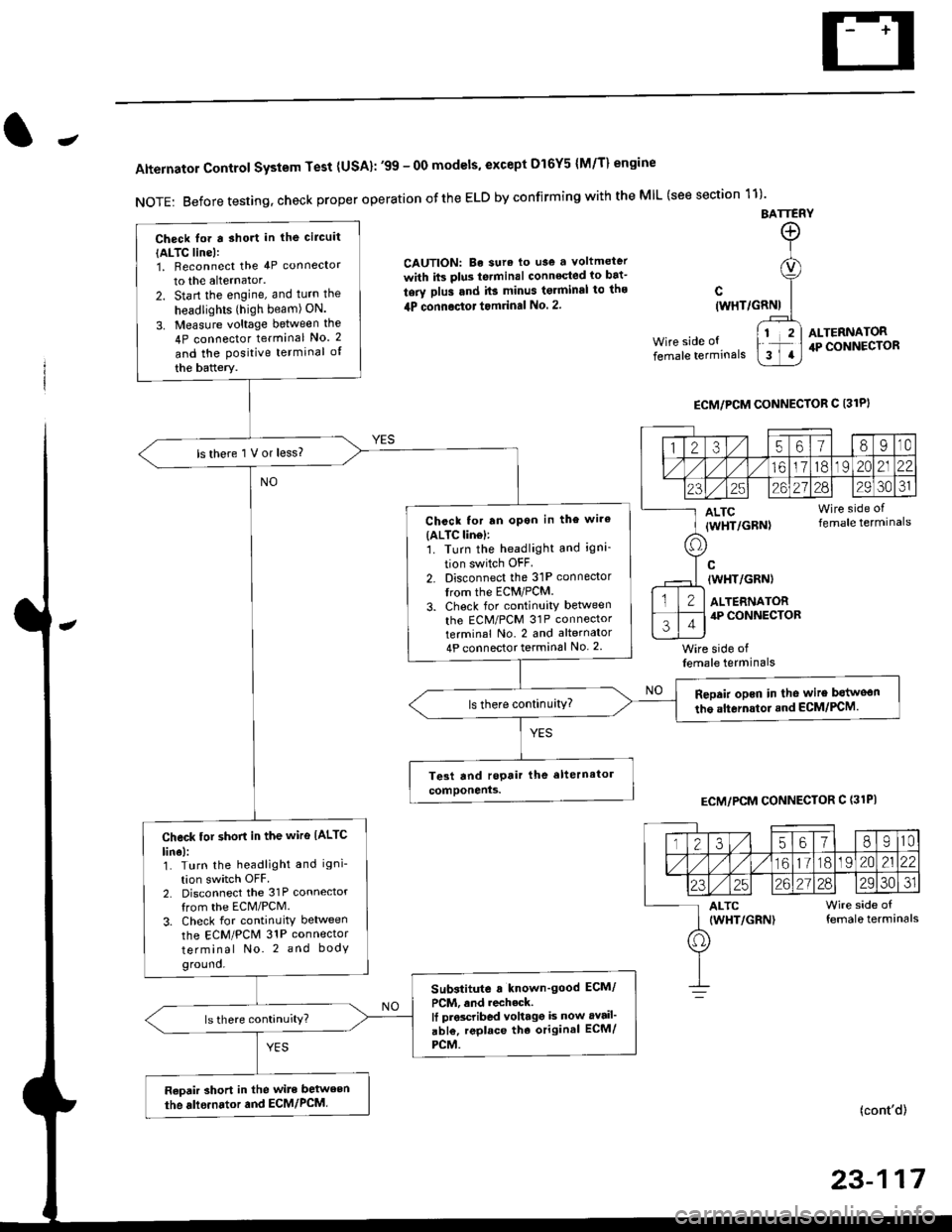
Alternator Control System Test {USA}: '99 - 0O models, except Dl6Y5 {M/T} engine
NOTE: Before testing, check proper operation ofthe ELD by confirming with the MIL (see section 11)'
BATTERY
CAUTION: Be sura lo use a voltmeter
with its plus te.minal conneqted io bat-
tery plus and it3 minus tgrminal to ths
4P connoctot tomrinal No. 2.
Wire side of
female terminals
c(WHT/GRNI
wire side offemale terminals
ALTERNATOR.P CONNECTOR
ECM/PCM CONNECTOR C 13lPI
ECM/PCM CONNECTOR C (31PI
(cont'd)
23-117
Check lor a sho.t in the circuit
{ALTC line):1, Beconnect the 4P connector
to the alternator.
2. Start the engine, and turn the
headlights (high beam) ON.
3. Measure voltage between the
4P connector terminal No. 2
and the Positive terminal of
the battery.
ls there 1 V or less?
Chcck for rn opon in the wire(ALTC lin6l:1. Turn the headlight and igni-
tion switch OFF
2. Disconnect the 31P connector
trom the ECM/PCM.
3. Check for continuity betlveen
the ECM/PCM 31P connectorterminal No. 2 and alternator
4P connector terminal No. 2
Repair opcn in the wire botweon
the alternstoi.nd ECM/PCM.ls there continuity?
Check tor short in the wire IALTC
line):1. Turn the headlight and igni-
tion switch OFF2. Disconnect the 31P connector
from the ECM/PCM.
3. Check for continuity between
the ECM/PCM 31P connector
terminal No. 2 and body
ground.
Substitute a known'good ECM/
PCM, and recheck.It prscribed voltagg is now avail'
abl€, replace tho original ECM/
PCM.
Raoair short in the wite between
the alle.nator and ECM/PCM,
1235618I10
/11611lo191 zo2122
23252621?82930JI
ALTC Wire side of(WHT/GRN) female terminals
o
Page 1607 of 2189
JBulb Locations {Without Tachometer)
TRUNK INDICATORLIGHT {1.i1W}
.4 Wl
CHARGING SYSTEM LIGHT 11,4 W}
LTGHT (1.4 W)GAUGE LIGHT
SEAT BELTREMINDER LIGHT (1.4 WI
LOW ENGINE OIL PRESSUBE
INDICATOB LIGHT (1.4 WI
LOW FUEL INDICATORLrGl{T (3 W)
RIGHT TURN SIGNALINOICATOR LIGHT
(1.1Wt
GAUGE LIGHTS {3 WI
WASHER LEVELINDICATOR LIGHT{1.4 W} lcanad.l
HIGH BEAMINDICATOR LIGHTMALFUNCTIONINDICATORLAMP (MIL)
BULB {1.4 WI
{1.ilW)
LEFT TURN SIGNALINDICATOR LIGHT {1.4 WI
A/T GEAR POSITIONINDICATOR (1.12 x 6)(On the printed
circuit board)
sRs TND|CATOR 11.4 W)
{On the Drinted circuit board}
aBs tNDtcAToR t1.4 W)(On the printed circuit board)(3.{ Wt
o/ o \7 o
23-137
Page 1632 of 2189
Lighting System
Gomponent Location Index (cont'dl
TURN SIGNAL INDICATOR LIGHTDASH LIGHTS BRIGHTNESSCONTROLLERController Input Test,page 23-119COMBINATION LIGHT SWITCHTest, page 23'165
TURN SIGNAL/HAZARD RELAYInput Test, page 23-'172
HIGH BEAM INOICATOR LIGHT
L ILI LILI LT
rr Lr rJ|r LJ Lr Lr rr !.r rr Lr rr I l-nnr1nr1r1r1r1|-1nn L JJ
r1 n11t'1n Ttr1 r1 - 11 t-1Tt-l T1r-t L.l Lt r-t r-t LJ ! ! LJ LJ ! LJ !J r-l
23-162
Page 1633 of 2189
Circuit Diagram (USA)
l|-
RED/BLK
II
I
\?
PABK NG LIGHTSTA LL GHTSL CENSE PLATE L GHTS
RED/ELK
III
I
r'
DASH LIGHTSDASH LIGHTSERIGHTNESSCONTROLLER
HIGH BEAMIND CATORLIGHT(r 4w)
REDiGRN
I
BLK
I
G401G4A2
UNDER,HOOD FUSEi NELAY 8OX
'------ --.-r ----.'r
-T
I" T,,: i.. T
o
UNDER DASH FUSE/RELAY 8OX
No5(104)No.4004)No 30(7.5A)
I)N0.32A {7.5A)
I
No 22(r0A)
AT
lilffl (
II
BLK
I
G201
8LK
I
:
G202
23-163