Page 1041 of 2189
Driveshafts
Reassembly
U.S. and Canada-Producad Driv€shafts
Note these items during reassembly'
. Clean the disassembled parts with solvent, and dry them thoroughly with compressed air, Do not wash the rubberpans with solvent.
o ;..jl@l : Thoroughly pack the inboard joint and both joint boots with the joint grease included in the new driveshaft
ser,
Grease quantity:
lnboard Joint115 - 135 g (4.0 - 4.8 oz)
Outboard Joint115 - 135 g (4.0 - 4.8 oz)
. The'98 Canada model and all '99 - 00 models uses a TPE (Thermoplastic Polyester Elastomerl outboard joint boot. Use
the ear clamp type boot band in the outboard joint boot set.
STOP RING('96 - 98 models)
-6rPack cavity with grease.
DYNAMIC DAMPER
OOUBI.S LOOP BANDReplace.
INBOARD BOOT
-6lPack cavity with grease.
EAB CLAMP BANDReplace.
STOP RINGReplace.
EAR CLAMP BANDReplace.
DRIVESHAFT
OUTBOARDBOOT ITPE)
-6ll
, Pack cavity with grease.
EAR CLAMP BANDReplace.
-G.1
CIRCLIP
16-8
OUTBOARD JOINT
Page 1043 of 2189
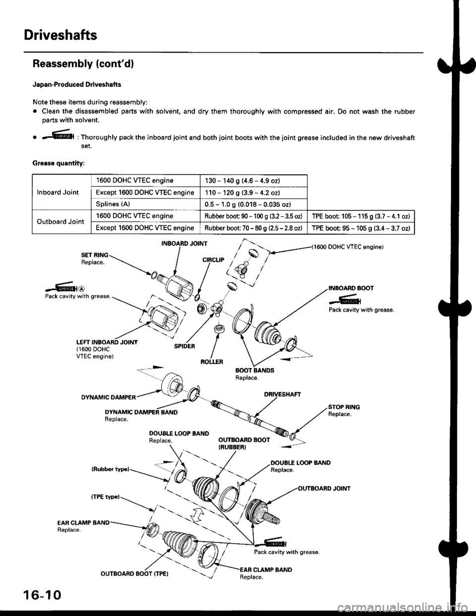
Driveshafts
Reassembly (cont'dl
Japan-Produced Driveshafts
Note these items during reassembly.
. Clean the disassembled pans with solvent, and dry them thoroughly with compressed air. Do not wash the rubber
parts with solvent.
o r@l : Thoroughly pack the inboard joint and both joint boots with the joint grease included in the new driveshaft
set.
Grease quantity:
Inboard Joint
1600 DOHC WEC engine130 - 140 9 (4.6 - 4.9 oz)
Except 1600 DOHC VTEC engine110 - 120 g (3.9 - 4.2 oz)
Splines (Al0.5 - 1.0 g (0.018 - 0.035 oz)
Outboard Joint
'1600 DOHC WEC engineRubber boot 90 - 'l 00 g (3.2 - 3.5 oz)TPE boot; 105 - 115 9 (3.7 - 4.1 oz)
Except 1600 DOHC VTEC engineRubber boot 70 - 80 g |'2.5 - 2.8 ozlTPE boot 95 - 105 g (3.4 - 3.7 oz)
{1600 DOHC VTEC angine)
SET RINGReplace.
-6{@INBOARD BOOT
-6;Pack cavity with grease.
Pack cavity with grease.
DYNAMIC DAMPER
DYNAMICReplace.
DOUA|.I Lq)P BANDReplace.
(Rubber typc)LOOP BANDReplace.
Pack cavity with grease-
CLAMP BAND
],*"u, ,"^S
/ t'.t$ ,''
,/s
-'-
OUTBOARD BOOTIRUEBER)
16-10
tttt t*' -----_.r...-
._
Replace.
Page 1049 of 2189
Driveshafts
Reassembly lcont'd)
Installthe outboard boot and the boot bands.. lf the boot is the rubber type. go to step 13.. lf the boot is the TPE type, go to step 9.
Fit the boot ends onto the driveshaft and outboard
ioint.
10, Set the ear clamp band by threading the tab into theholes of the band.
EAR CLAMP BANDReolace.
8.
16-16
11. Close the ear portion of the band with a commer-cially available boot band Dincerc.
BOOT BAND PINCERSKENT-MOORE J,35910or eouivalent
Chsck the clearanca between the closed ear oonionof the band. lf the clesrance is not within the stan-
dard, close the ear portion of ths band further.
6.0 mm (0.24 in) MAX
3.0 mm 10.t2 inl MAX
EAR FOFNON
Page 1063 of 2189
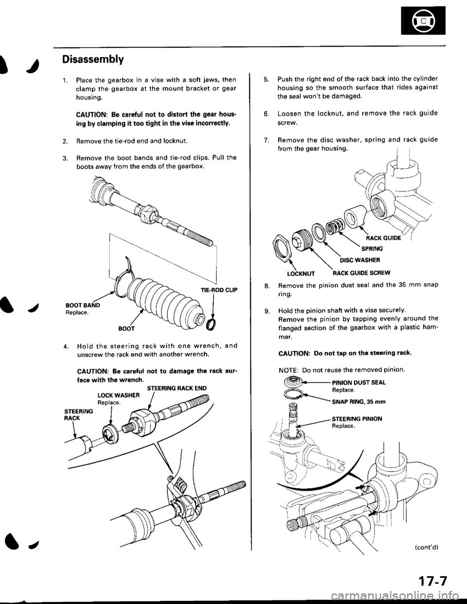
)
Disassembly
'1.
2.
Place the gearbox in a vise with a soft jaws, then
clamp the gearbox at the mount bracket or gear
housing.
CAUTION: Be carcful not to distort the gear hous-
in9 by clamping it too iight in the vise incorrectly.
Remove the tie-rod end and locknut.
Remove the boot bands and tie-rod clips. Pull the
bogts away from the ends of the gearbox.
/
TIE.ROD CLIP
4. Hold the steering rack with one wrench, and
unscrew the rack end with another wrench.
CAUTION: Be caleful not to damagc the rack sur'
facs with the wrench.
STEERING RACK ENO
l,
17-7
7.
Push the right end of the rack back into the cylinder
housing so the smooth surface that rides against
the seal won't be damaged.
Loosen the locknut, and remove the rack guide
screw.
Remove the disc washer, spring and rack guide
from the gear housing.
RACK GUIOE
SPRING
8.
9.
LOCKNUT RACK GUIDE SCREW
Remove the pinion dust seal and the 35 mm snap
nng.
Hold the pinion shatt with a vise securely
Remove the pinion by tapping evenly around the
flanged section of the gearbox with a plastic ham-
met.
CAUTION: Do not tap on tho steering rack.
NOTE| Do not reuse the removed pinion.
9._
ViF=\_
PINION DUST SEALReplace.
SNAP RING,35 mm
STEERING PINIONFeplace.
DISC WASHER
Page 1070 of 2189
Steering Gearbox
Installation (cont'dl
Center the cable reel by first rotating it clockwise
until it stops. Then rotate it counterclockwise(approximately two turns) until the arrow mark on
the label points straight up. Reinstall the steering
wheel (see page 17-35).
Install the steering joint cov€r with the clamps and
clrps.
7.
STEERING JOINI COVER
17-14
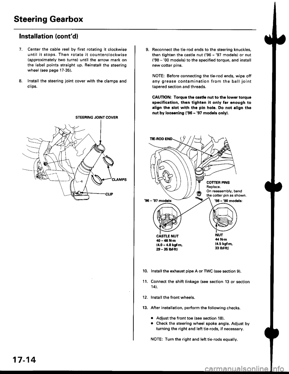
9. Reconnsct the ti€-rod ends to the steering knuckles,
thon tightsn th€ castle nut ('96 -'97 models) or nut('98 -'00 models) to the specified torque, and install
new cotter pins.
NOTE: Before connecting the tie-rod ends, wipe off
any grease contamination from the ball joint
tapered section and threads.
CAUTION: Torque lhe ct3tle nut to thr lowsr torque
spocification, th€n tighton it only tar anough to
align the 3lot with tho pin hob. Do not align the
nut by loosening ('96 - '97 modcls onlyl.
TIE.ROD
COTTER PINSR6plac6.On rgassombly, b6nd
'96 - 37 model3:
cotter prn as shown.'98 - '00 modol3:
NUT4a N.m(4.5 kgf.m,33 lbr.ftl
CAST1T NUT,O - ilt N'm{4,0 - 4.8 kgf.m.29 - 35 tbtftl
10.Installthe exhaust pipe A or TWC (see section 9).
Connect the shift linkage (see section 13 or section
14).
Install the front wheels.
After installation, perform the following checks.
. Adjust the front toe (see section 18).. Check the steering wheel spoke angle. Adjust by
turning the right and left tie-rods, if necessary.
NOTE: Turn the right and left tie-rods equally.
ll.
Page 1083 of 2189
)
Pump noaseGrating noisefrom pump
Pump gear nois€
Check the tluid level.
lf low, fill the reservoir to the
proper level, and check lor leaks.
Tighten or replace as nocessary.
Cavitation caused bY air bubbles
in the fluid.
Check lor a crushed suction hose
or a loose hose clamp allowing
air into the suction side of the
sy$em.Tighton or roplace as necossary.
NOTE: Pump noise uP to 2 - 3
minutes alter starting in cold
weather is normalCompare pumP noise at operating
temperature to simular vehicle.
lf pump nois€ is abnormallY loud,
remove and inspect the PUmP for
w6ar and damage (see Page 17-
41).
lz/
Rattle or chattgring
17-27
Tighten or replace the Pulley.lf shatt is loose, rePlace thepump.
tr
Page 1095 of 2189
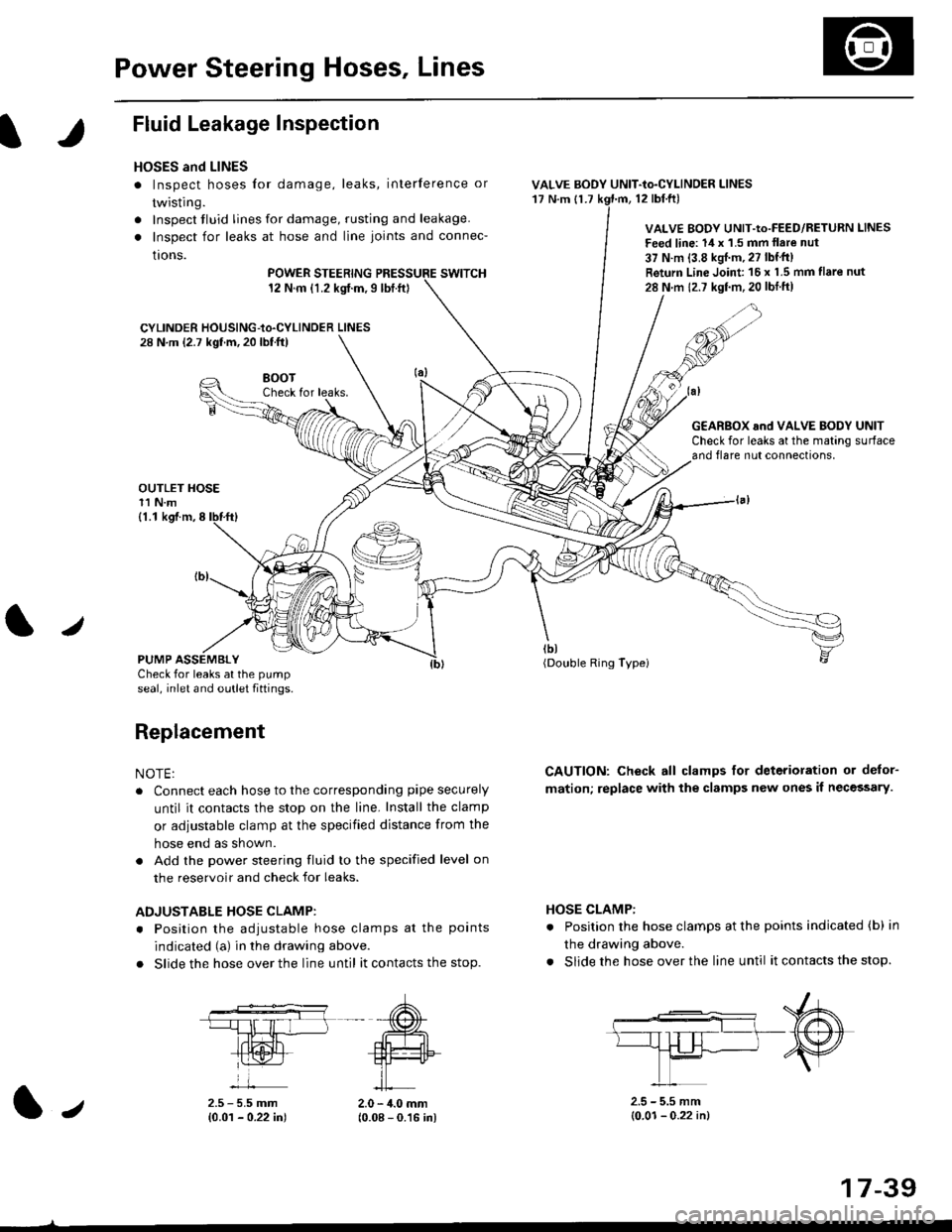
Power Steering Hoses, Lines
Fluid Leakage Inspection
HOSES and LINES
. Inspect hoses for damage, leaks, interference or
twisting.
. Inspect tluid lines for damage, rusting and leakage.
. Inspect for leaks at hose and line joints and connec-
tions.
POWER STEERINGswtTcH12 N.m {1.2 kgt.m,9lbt.ft}
CYLINDER HOUSING-to.CYLINDER LINES28 N.m (2.7 kgf.m, 20 lbf.ft)
VALVE BODY UNIT-to-CYLINDER LINES'17 N.m {1.712 tbl.ftl
VALVE BODY UNIT-Io-FEED/RETURN LINES
Feed line: 14 x '1.5 mm llare nut
37 N.m {3.8 kgJ.m, 27 lbf'tt)
Return Line Joint 16 x 1.5 mm flare nut
28 N m 12.7 kgf.m,20 lbtft)
HOSE CLAMP:
. Position the hose clamps at the points indicated (b) in
the drawing above.
. Slide the hose over the line until it contacts the stop.
8()07Check for leaks.
OUTLET HOSE11 N.m
G€AR8OX and VALVE BODY UNITCheck for leaks at the mating surfaceand flare nut connections,
tbt(Double Ring Typei
CAUTION: Check all clamps for deterioration or delor-
mation; replace with the clamps new ones il necessary.
(1.1 kgf.m,8
PUMP ASSEMBLYCheck for leaks at the pump
seal, inlet and outlet fiftings.
Replacement
NOTE:
. Connect each hose to the corresponding pipe securely
until it contacts the stop on the line. Install the clamp
or adiustable clamp at the specified distance from the
hose end as shown.
. Add the power steering fluid to the specified level on
the reservoir and check for leaks.
ADJUSTABLE HOSE CLAMP:
. Position the adiustable hose clamps at the points
indicated (a) in the drawing above.
. Slide the hose over the line until it contacts the stop.
2.5 - 5.5 mm{0.01 - 0.22 in)2.0 - 4.0 mm(0.08 - 0.16 in)
2.5 - 5.5 mm(0.01- 0.22 in)1.,
17-39
Page 1099 of 2189
I
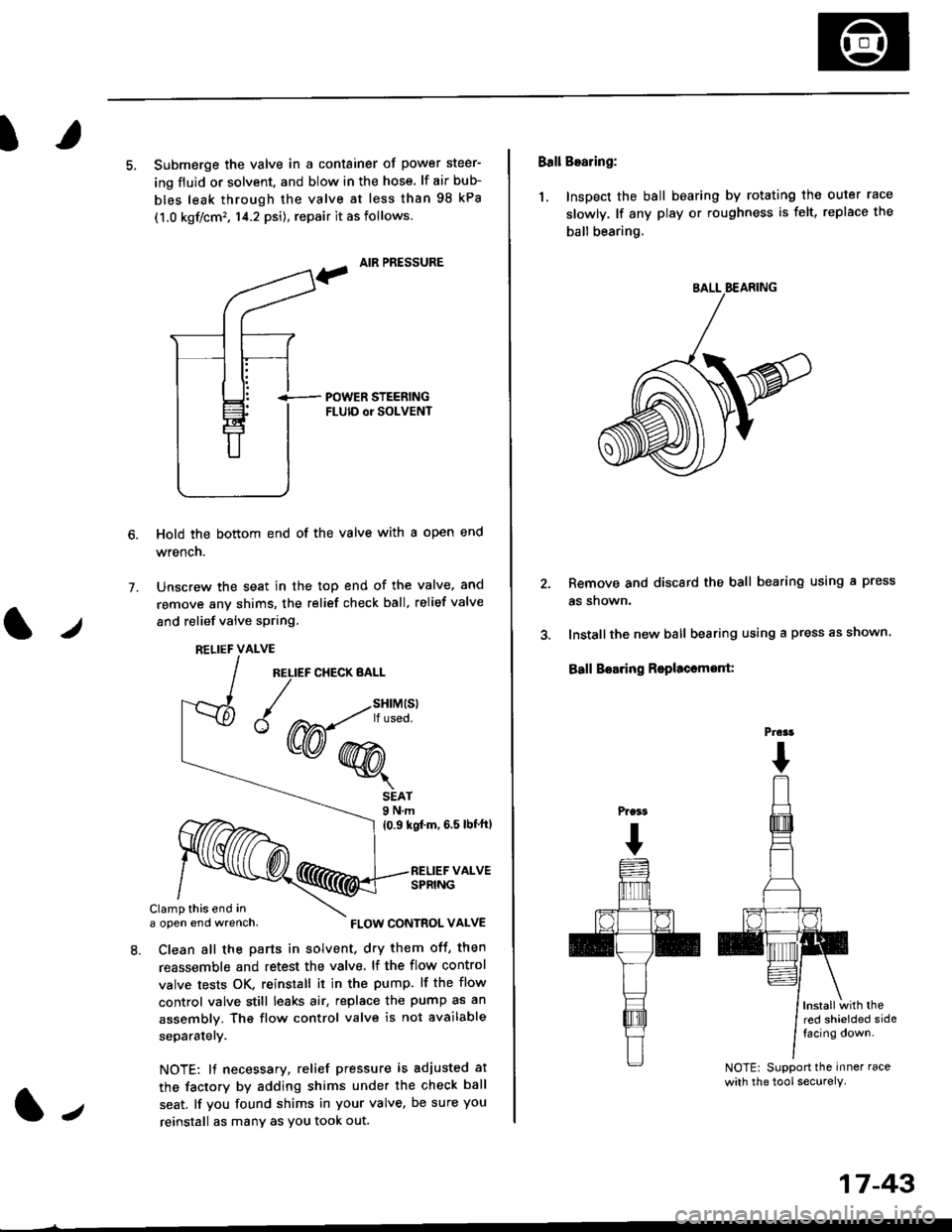
5, Submerge the valve in a container of power steer-
ing fluid or solvent. and blow in the hose. lf air bub-
bles leak through the valve at less than 98 kPa
(1.0 kgf/cm'�, 14.2 psi), repair it as follows.
, AIR PRESSURE
?
i-- POWER STEERTNGFLUID or SOLVENT
Hold the bottom end of the valve with a open end
wrench.
Unscrew the seat in the top end of the valve. and
remove any shims, the relief check ball. relief valve
and relief valve spring.
7.
l./
RELIEF CHECK BALL
1.,
SEAT9 N.m
{0.9 kgf'm, 6.5 lbt'ftl
RELIEF VALVESPRING
Clamp this end ina open end wrench,
8. Clean all the parts in solvent, dry them off, then
reassemble and retest the valve. lf the flow control
valve tests OK, reinstall it in the pump. lf the flow
control valve still leaks air, replace the pump as an
assembly. The flow control valve is not available
separatelY.
NOTE: 11 necessary, relief pressure is adjusted at
the factorv by adding shims under the check ball
seat. lf you found shims in your valve, be sure you
reinstall as many as You took out.
RELIEF VALVE
{W-*"'
FLOW CONTROL VALVE
17-43
Ball Bearing:
1. Inspect the ball bearing by rotating the outer race
slowly. lf any play or roughness is felt, replace the
ball bearing.
Remove and discard the ball bearing using a press
as snown.
Installthe new ball bearing using a press as shown.
Ball Boaring Rsplaccmont:
lnstallwith thered shielded sidefacing down.
NOTE: Support the inner race
with the tool securely.
BALL BEARING
Prcrt