Page 919 of 2189

Electrical Troubleshooting ('96 - 98 Modelsl
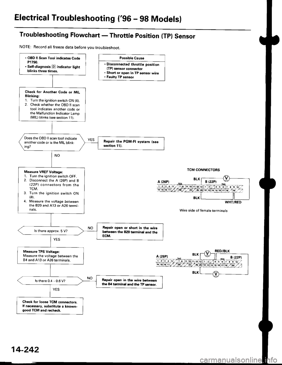
Troubleshooting Flowchart - Throttle position (Tpl Sensor
Possible Cause
. Disconnected throftle position(TPl 3ensor connoctol. Short or open in TP sensor wire. Fauhy TP sensol
TCM CONNECTORS
Wire s;de of female terminals
. OBO ll Scan Tool indic.tes CodeP1790.. Self-diagnosis E indicator lightblinks three times.
Check lor Anothar Code or MILBlinking:1. Turn the ignition switch ON 1 ).2. Check whether the OBD ll scantool indicates another code orthe Malfunction Indicator Lamp(MlL) blinks (see secrion 11).
Does the OBD ll scan tool indicateanothercode oristhe MIL blink-ing?
Repair the PGM-FI systom (3eesection 111.
Measure VREF Voltage:1. Turn the ignition switch OFF.2. Disconnect the A (26P) and B{22P} connectors lrom theTCM.3. Turn the ignition switch ON{fl).4. Measure the voltage bet\iveenthe 820 and A13 or 426 termi-nals,
Repair open or short in thc wireb,stween the Bao tcrminal rnd theECM.
ls lhere approx. 5 V?
Measure TPS Voltago:Measure the voltage between theB4 and A13 or 426 terminals.
Repail open in the wire tr€tweonthe Erl t6.minal ind the TP sen3o..ls there 0.4 - 0.6 V?
Check for loose TCM connectors.lf necessary, substitute a known-good TCM and r6check.
NOTE: Record all freeze data before you troubleshoot.
BLK
WHT/RED
A {26P1
Page 926 of 2189

Troubleshooting Flowchart - Manifold
NOTE: Record all freeze data before you troubleshoot
Absolute Pressure {MAPI Sensor
TCM CONNECTORS
Wire side of female terminals
PG.iblo Cau3€
. Dkconnoctod manilold .bsoluto
ore33urc IMAP) sensor connoc'
lor. Short or opcn in MAP s.nsor
MAP sen3or
. OBD ll Scan Tool indicates Code
P1793,. self-diagno3b E indicato. light
indicat€s Code 12.
Chock tor Another Cod€ or MIL
Blinking:1. Turn the ignition switch ON (ll).
2. Check whether the OBD ll scan
tool indicates another code or
the Mal{unction Indicator LamP(MlL) blinks (sse section 11).
Does the OBD llscan tool indicate
another code or isthe lVlL blink-
in9?
Measure VREF voltage:
1. Turn the ignition switch OFF.
2. Disconnect the A (26P) and B
(22P) connectors trom the
TCM.3. Turn the ignition switch ON (ll).
4, Measure the voltage between
the B2O and A13 or A26 termr
nals.
R€pair opon or 3hort in the wire
botwoan the 820 t€.minal and
the EcM.lsthere aPprox.5 V?
Msasure MAP IPB) volt.ge:
Measure the voltage betlveen the
82 and A13 or 426 terminals.
Repair opon ot shorl in the wiro
betwesn the 82 torminal end th€
MAP sensol.ls there approx. 3 V?
Check for loo3e TCM conn€stors.
lf nec*sarY, sub3titute a known'
good TCM and rechock.
WHT/RED
14-249
Page 1027 of 2189

22. Install the shift cable end on the control lever, and
install the shift cable on the shift cable bracket'
CAUTION: Take care not to bend the shift cable'
23. lnstall the clip in the direction shown.
LOCKNUT
SHIFI CABLE 29 N m {3.0 kg{ m, 22lblftl
SHIFT CABLEERACKET
WASHERIPLASTIC)
CONTROL LEVER
24, Connect the solenoid harness connector. the drive
pulley speed sensor connector. and the ground
cable terminals.
6x1.0mm12 N.m {1.2 kgf.m.8,7 rbtft)
GROUND CABLETERMINAL 6x1.0mm
GROUNDTERMINAL
12 N.m {1.2 kgf'm,8.7lbtfrl
DRIVE PULLEYSPEED SENSORCONNECTOR
SOLENOID HARNESS
CONNECTOR
25. Connect the starter motor cable on the starter motor.
and install the cable holder.
NOTE: When installing the staner motor cable. make
sure that the crimped side of the ring terminal is
facing out (see section 23).
STARTEB
BMOUNTING NUT
9 N.m (0.9 kgf m,7 lbf ft)
26. Install all removed connectors and clamps'
27. Install the distributor.
28. Install the intake air duct and air cleaner housing
29.
assemDly.
Refill the transmission with the recommended
Genuine Honda CVT Fluid (see page 14-2991
CAUTION: While filling the CvT Fluid, bs surs not io
allow dust and other fotoign particles to entor into
the transmission.
Connect the battery positive (+) terminal first, then
the negative (-l terminal to the battery'
Check the ignition timing (see section 23).
Start the engine. Set the parking brake, and shift the
transmission through all gears three times Check
shift cable adjustment (see page 14-355).
Check the front wheel alignment (see section 18)
Let the engine reach operating temperature (the
radiator fan comes on) with the transmission in lXl
or E position, then turn it off and check fluid level'
Perform the start clutch calibration procedure on
page 14-293.
Road test as described on pages 14-296 and 14-297
30.
31.
34.
36.
STARTER MOTOR
14-351
Page 1028 of 2189

Transmission
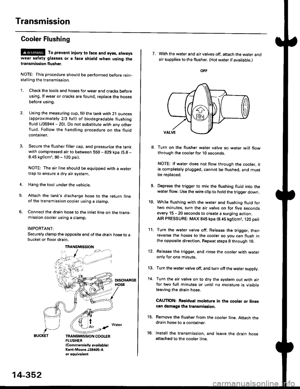
Gooler Flushing
@ To prevent iniury to face and eyes, alwayswear safety glasses or a tace shield when using thetransmission flusher.
NOTE: This procedure should be performed before rein-stalling the transmission.
'1. Check the tools and hoses for wear and cracks before
using. lf wear or cracks are found, reDlace the hoses
before using.
4.
Using the measuring cup. fill the tank with 2,1 ounces(approximately 2/3 full) of biodegradable flushingfluid (J35944 - 20). Do not substitute with any otherfluid. Follow the handling procedure on the fluidcontatner.
Secure the flusher filler cap, and pressurize the tankwith compressed air to between 5S0 - 829 kpa (5.6 -
8.45 kgf/cm'�, 80 - 120 psi).
NOTE: The air line should be equipped with a watertrap to ensure a dry air system,
Hang the tool under the vehicle.
Attach the tank's discharge hose to the return lineoi the transmission cooler using a clamp.
Connect the drain hose to the inlet line on the trans-mission cooler using a clamp.
IMPORTANT:
Securely clamp the opposite end ofthe drain hose to abucket or floor drain,
t
TRANSMISSION COOLERFLUSHER{Commercially available)Kent-Moore J384O5-Aor oouivalent
TRANSMISSION
14-352
7. With the water and air valves off, attach the water andair supplies to the flusher. (Hot water if available.)
8. Turn on the flusher water valve so water will flowthrough the cooler for 10 seconds.
NOTE: lf water does not flow through the cooler, itis completely plugged, cannot be flushed, and mustbe replsced.
9. Depress the trigger to mix the flushing fluid into thewater flow. Use the wire clip to hold the trigger down.
'10. While flushing with the water and flushing fluid fortwo minutes. turn the air valve on for five secondsevery 15 - 20 seconds to create a surging action.AIR PRESSURE: MAX 845 kpa (8.45 kgflcmr, 120 psi)
11. Turn the water valve off. Release the trigger, thenreverse the hoses to the cooler so you can flush inthe opposite direction. Repeat steps 8 through 10.
12. Release the trigger. and rinse the cooler with wateronly for one minute.
13, Turn the water valve off, and turn off the water supply.
'14. Turn the air valve on to dry the system out with airfor two full minutes or until no moisture is visibleleaving the drain hose.
CAUTION: Rosidual mobturo in the qooler or linescln damage the transmission,
15. Remove the flusher from the cooler line. Attach thedrain hose to a container.
16. Install the transmission. and leave the drain hoseattached to the cooler line.
Page 1030 of 2189
Shift Cable
RemovaUlnstallation
@ Make sure lifts, iacks and safety stands are
placed properly (see seqtion 11,
1. Remove the front console (see section 20).
2. Shift to E position, then remove the lock pin from
the adiuster.
ADJUSTER
14-354
Remove the air cleaner housing assembly.
Remove the clip from the control lever, and loosen
the locknut.
CLIP SHTFT CABLE LOCKNUT29 N.m 13.0 kgf m,22 lbf.ft)
SHIFT CABI-EBRACKET
7.
8.
CONTROL LEVER
Remove the shift cable from the control lever, the
shift cable bracket, and the clamp.
Remove the shift cable bracket bolts and nuts, then
remove the shift cable. Take care not to bend the
shift cable when removing/installing it.
SHIFT CABLE BRACKET
lnstall the shift cable in the reverse order of removal.
Check the cable adjustment (see page 14-355).
\.
*o"ra" \
{1.2 kgI m, 8.7 lblft)
Page 1032 of 2189
Shift Lever
KNOBLEVER
SCREW
,l
PUSH KNOE SPRING
SHIFTPUSH KNOB
\
e
X./
,/
-6rSILICONE GREASE
SHIFT INDICATOR LAMP.
SCREW3 N.m 10.3 kgl.m.2 lbf.ttl
/ tnrnJl / I 3 N.n l0.3 xgt m, 2 lbf ftl
a,-,/ / Apply non-hardening th'
\2 I
Apply non-hardening thread lock sealant.
SCREW3 N.m {0.3 kgf'm, 2 lbl.ft)
A/T GEAR POSTTON INDICATOR PANEL
LEVER COVER
A/T GEAR POSMON SWNCH
BUSHING
-611SII.'|CONE GREASE
SHIFT I.TVEB ASSEMBLY
dE("""-- L@KP'N
n2
SHIFT LOCKsotENolD
6x1.0mm9,8 N.m 11.0 kgf.m,7.2 tbtft)-
A/T GEAR POSITIONPLAYE
3 N.m 10,3 kqf.m,2tbfitl
SHIFT LEVEN BRACKET BASE
SHIFT LEVER
6x1.0mm9.8 N.m {1.0 kgf.m,7.2 lbf ftl
BASE COLLAR
14-356
Page 1038 of 2189
t
Disassembly
lnboard Joint Side:
1. Carefully clamp the driveshaft in a vise with soft
jaws, then remove the set ring from the inboard
joint.
2. Remove the boot bands. Take care not to damage
the boot.
. lf the boot band is a locking tab type, pry up the
locking tabs with a screwdriver, and raise the
end of the band.
. It the boot band is a welded type, cut the boot
ba nd.
. lf the boot band is a crimping type, pry up the
end of the band with a screwdraver.
. lf the boot band is a double loop type, lift up the
band bend.
Locking Tab Typs
Welded Type
J
Replace.
l,
Crimping Type
Double Loop Type
Mark each roller and inboard joint to identify the
locations of rollers and grooves in the inboard joint.
Then remove the inboard joint on the shop towel.
Be careful not to drop the rollers when separating
them from the inboard ioint.
INBOARD JOINTCheck splines for wear or damage,Check inside bore for wear.Inspect for cracks.
(cont'd)
16-5
Page 1040 of 2189
1
4.
Wipe off the grease to expose the driveshaft and
the outboard ioint inner race.
Mark the driveshaft at the same position of the out-
board joint end with paint.
5. Carefullv clamp the driveshaft in a vise.
THREADED ADAPTER, 24 x 1.5 mm
07xac - (x)102(x)
Remove the outboard joint using a special tool as
snown.
7.
8.
Remove the driveshaft from the vise
Remove the stop ring from the driveshaft.
DRIVESHAFT
Feplace.
16-7