1998 HONDA CIVIC Thrust
[x] Cancel search: ThrustPage 58 of 2189
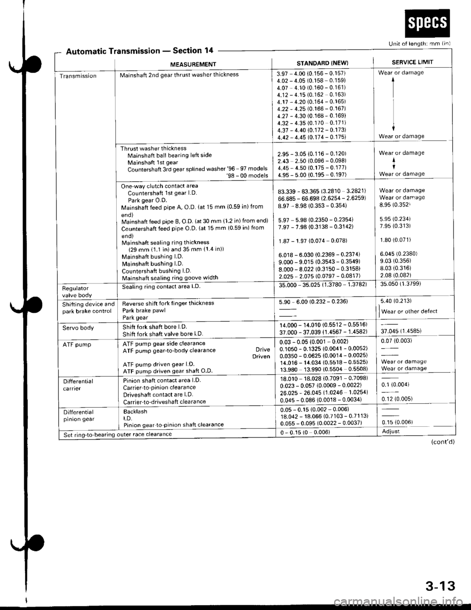
Automatic TnsmtsstonSection 14Un;t of length: mm {in)
r
MEASUREMENT
a
STANDARD INEW)SEBVICE LIMIT
TransmissionMainshaft 2nd gear thrust washer thickness
Thrust washer thicknessMainshaft ball bearing left sideMainshaft lst gear
Countershaft 3rd gear splined washer '96 97 models'98 - 00 models
One-way clutch contact area
Countershaft 1st gear LD.
Park gear O.D.Mainshaft feed pipe A, O.D. (at 15 mm (0.59 inlfrom
Mainshaft feed pipe B, O.D. (at 30 mm {1.2 in) from end)
Countershaft feed pipe O.D. lat 15 mm (0 59 in) from
eno)Mainshaft sealing ring thickness
129 mm 11.1 iniand 35 mm {1.4 in))
Mainshaft bushing l.D.
Mainshaft bushing LD.
Countershaft bushing LD.Mainshaft sealing ring goove width
3.97 4.00 10.156 - 0.157)4.02 - 4.05 (0.158 0.159)
4.07 - 4.10 (0.160 - 0.161)4.12 - 4.15 (0.162 0.163)
4.17 - 4.20 10.164 - 0.165)4.22 - 4.25 (0.166 - 0.167)4.27 - 4.30 (0.168-0.169)
4.32 - 4.35 (0.170 0.171)
4.37 - 4.40 10.172 - 0.173)
4.42 - 4.45 10.114 - 0.175l
1
I
+Wear or damage
2.95 - 3.05 {0.116 - 0.120)2.43 2.50 (0.096 - 0.098)4.45 - 4.50 (0.175 - 0.177i4.95 - 5.00 (0.195 0.197)
Wear or damage
+I
83.339 - 83.365 (3.2810 3.2821)
66.685 - 66.698 (2.6254 - 2.6259)
8.97 - 8.98 (0.353 - 0.354)
5.97 5.9810.2350 - 0.2354i7.97 - 7.98 (0.3138 - 0.3142)
1.87 - 1.97 {0.074 0.078)
6.0 r8 - 6.030 {0.2369 - 0.2374)
9.000 - 9.01s 10.3543-0.3549)8.000-8.022 (0.3150 - 0.3158)
2.025 - 2.015 l0.0197 -0.0417)
Wear or damageWear or darn age
8.95 (0.352J
5.95 (0.234)
7.95 (0.313)
1.80 (0.071)
6.045 (0.2380)
9.03 (0.356)
8.03 {0.316)2.08 (0.082)
Regulatorvalve body
Seating ring conlact area l.D.35.000 35.02511.3780 1.3782)35.050 (1.3799)
Shifting device andpark brake controlReverse shift fork Iinger thicknessPark brake pawl
Park gear
5.90 - 6.00 (0.232 - 0.236)5.40 (0.213)
lWear or other defect
Servo bodyShift fork shaft bore LD.
Shift fork shaft valve bore l.D.
14.000 - 14.010 (0.5512 - 0.5516)
37.000 - 37.039 (1.4567 - 1.4582)37.045 (1.4585)
ATF pumpATF pump gear side clearanceATF pump gear-to-body clearance DriveDaiven
ATF pump driven gear LD.ATF pump driven gear shaft O.D
0.03 -0.05 {0.001 - 0.002)0.1050 - 0.1325 (0.0041 - 0.0052)
0.0350 - 0.0625 (0.0014 - 0.0025)14.0'�|6 - 14.034 {0.5518 - 0.5525i13.980 13.990 (0.5504 0.5508)
0.07 (0.003)
Differentialcarrier
Pinion shaft contact area LD.
Carrier to'pinion clearanceDriveshaft contact are LD.
Carrier to-driveshaft clearance
18.010 18.028 {0.7091 0.7098)
0.023 - 0.057 (0.0009 -0.0022)
26.025 * 26.045 11.0246 1.0254)
0.045 - 0.086 (0.0018 - 0.0034)
0.1 {0.004)
0.12 {0.005)
Differentialprnron gearBacklasht.D.Pinion gear to-pinion shaft clearance
0.05 - 0.15 {0.002 - 0.006)18.042 - 18.066 (0.7103 - 0.7113i0.055 - 0.095 (0.0022 - 0.0037)ffi.oour
Set ring-to bearing outer race clearance0 - 0.15 (0 0.006)Adjust
(cont'd)
3-13
Page 60 of 2189
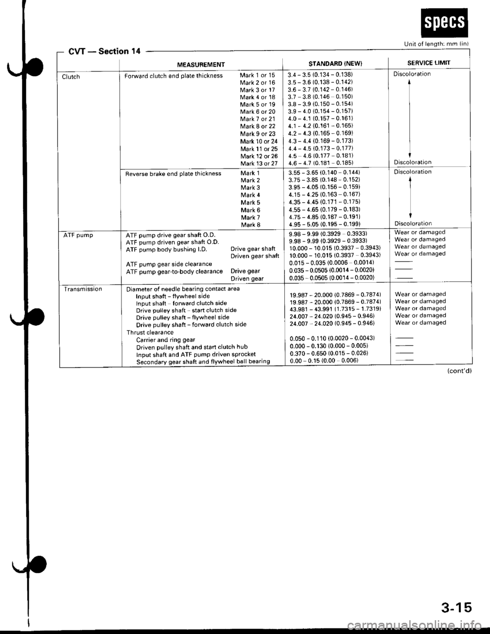
cwSection 14[Jnit of length: mm (in)
MEASUBEMENTSTANDARD {NEW}SERVICE LIMIT
Forward clutch end plate thickness Mark 1 or 15Mark 2 or 16Mark 3 or 17Mark 4 or 18Mark 5 or 19Mark 6 or 20Mark 7 or 21Mark 8 or 22Mark I or 23Mark 10 or 24Mark 11 or 25Mark 12 or 26Matk 13 ot 21
3.4 - 3.5 10.134 - 0.138)
3.5 - 3.6 (0.138 - 0.142)3.6 - 3.7 (0.142 - 0.146)3.7 3.8 (0.146 0.150)3.8 - 3.9 (0.150 - 0.154)3.9 - 4.0 (0.154 - 0.157i4.0 - 4.1 (0.157 - 0.161)4.1 - 4.2 (0.161 - 0.165)4.2 - 4.3 (0.165 - 0.169)4.3 - 4.4 (0.169 - 0.173)4.4 - 4.5 10.173 - 0.177i4.5 4.6 (0.177 0.181)4.6 - 4.7 (0.181 - 0.185)
Discoloration
Discoloration
Reverse brake end plate thickness Mark 1Mark 2Mark 3Mark 4\44 rk 5Mark 6Mark 7Mark 8
3.55 - 3.65 (0.140 0.144)3.75 - 3.85 10.148 - 0.152)
3.95 - 4.05 (0.156 - 0.159i4.15 - 4.25 (0.163 0.167)4.35 - 4.45 (0.171 - 0.175)
4.55 - 4.65 (0.179 - 0.183)4.75 - 4.85 (0.187 - 0.191)4.95 - 5.05 (0.195 - 0.199)
Discoloration
1
IDiscoloration
ATF pumpATF pump drive gear shaft O.D.ATF pump driven gear shaft O.D.ATF pump body bushing l.D. Drive gear shaftDriven gear shaft
ATF pump gear side clearanceATF pump gear-to-body clearance Drive gear
Driven gear
9.98 - 9.99 (0.3929 0.3933)9.98 - 9.99 {0.3929 - 0.3933)10.000 - 10.015 (0.3937 0.3943)10.000 - 10.015 (0.3937 0.3943)
0.01s - 0.035 (0.0006 0.0014)
0.035 - 0.0505 (0.0014- 0.0020)
0.035 - 0.0505 (0.0014 - 0.0020)
Wear or damagedWear or damagedWear or damagedWear or damaged
TransmissionDiameter of needle bearing contact areaInput shaft - flywheel sideInput shaft forward clutch sideDrive pulley shaft - start clutch sideDrive pulley shaft - flywheel side
Drive pulley shaft - forward clutch side
Thrust clearanceCarrier and ring gear
Driven pulley shaft and start clutch hub
Input shaft and ATF pump driven sprocketSecondary gear shaft and flywheel ball bearing
19.987 - 20.000 (0.7869 - 0.7874)19.987 - 20.000 (0.7869 - 0.7874)43.981 - 43.991 (1.7315 - 1.7319)24.007 - 24.020 (0.945 - 0.946)24.007 - 24.020 (0.945 - 0.946)
0.050 - 0.110 (0.0020 - 0.0043)
0.000 - 0.130 10.000 - 0.005)
0.370 - 0.650 (0.015 - 0.026)0.00 0.15 (0.00 0.006)
Wear or damagedWear or damagedWear or damagedWear or damagedWear or damaged
(cont'd)
3-15
Page 61 of 2189
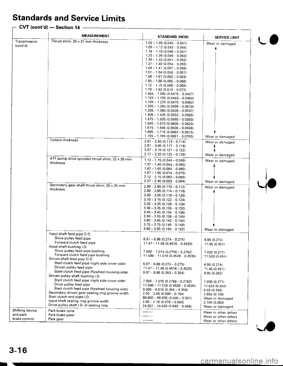
Transmission(cont'd)
MEASUREMENT
Thrust shim,25 x 31 mm thickness
STANDARD {NEW}
rlz-r-osr-o.o+o oolrr1.09 - 1.12 (0.043 0.044)1.16 1.19 (0.046 - 0.047)1.23 1.26 (0.048 0.050)1.30 - 1.33 (0.051 0.052)1.37 - 1.40 (0.054 0.055)1.44 - 1.47 (0.057 0.058)1.51 1.54 (0.059 0.061)1.58 1.61 (0.062 - 0.063)1.65 - 1.68 (0.065 0.066)1.72 1.75 {0.068 0.069)1.79 1 .a2 t0.O10 - 0.012]}1.055 1.085 (0.0415 0.0427)1.125 - 1.155 (0.0443 0.0454)1.195 - '�I.225 (0.0470 0.0482)1.265 - 1.29s (0.0498 0.0510)1.335 1.365 (0.0526 - 0.0537)1.40s - 1.435 (0.0553 - 0.0565)r.475 1.505 {0.0580 0.0593)1.545 1.575 (0.0608 0.0620)1.615 1.645 (0.0636 - 0.0648)1.685 1.71510.0663 - 0.0675)1.755 - 1.785 {0.0691 0.0703)
SERVICE LIMIT
I Wr"r - d-"-"g"d
ii
11
ir
Cotters thickness2.87 - 2.90 (0.1 13 - 0.114)2.97 - 3.00 (0.117 0.118)3.07 -3.10 \0.121 0.122)3.17 - 3.20 (0.125 0.126)
Wear,or damaged
IWear or damaoedATF pump drive sprocket thrust shim, 22 x 28 mmthickness1.12 1.1510.044 - 0.045)1.37 1.40 (0.054 - 0.055)1.62 - 1.65 (0.064 0.065)1.87 - 1.90 (0.074,0.075)2.12 2.15 (0.083 - 0.08s)2.37 2.40 (0.093 0.094)
Wear or damaged
t
{Wear or damagedSecondary gear shaft thrust shim, 25 x 35 rnmthickness2.80 - 2.85 (0.1'�t0 - 0.112)2.90 2.95 (0.114 - 0.116)3.00 3.05 (0.118 - 0.120)3.10 -3.15 10.122 0.124)3.20 - 3.25 (0.126, 0.128i3.30 - 3.35 (0.130 0.132)3.40 - 3.4s 10.134 0.136)3.50 3.55 (0.138 - 0.140)3.60,3.65 (0.142 0.144)3.70 - 3.75 (0.146 0.148)3.80 - 3.8510.150 0.152)
Wear or damaged
Wear or damaqedInput shaft feed pipe O.D.Drive pulley leed pipeForward clutch feed pipeInput shaft bushing t.D.Drive pulley feed pipe bushingForward clutch feed pipe bushingDriven shaft feed pipe O.D.Start clutch feed pipe (right side cover side)Driven pulley feed pipeStan clutch feed pipe (ftywheet housing side)Driven pulley shaft bushing LD.Stan clutch feed pipe (right side cover sroerDrive pulley feed pipeStart clutch feed pipe (flywheel housing side)Secondary driven gear sealing ring groove widthStart clutch end plate l.D.Input shaft sealing ring groove widthDnve pullev shaft LD. at sealing ring
Park brake conePark brake pawlPark gear
6.97 - 6.98 (0.274 - 0.27s)11.47 - 1'1.48 (0.4516 0.4520)
7.O0O 7.0t510.2156 - 0.2762]l11.500 11.518 (0.4528 0.4535)
6.97 - 6.9A \0.214 0.275:l11.47 - 11.48 (0.4516 _ 0.4520)8.97 8.98 10.353 - 0.354)
7.000 7.015 (0.2756 - 0.2762)1 1.500 - '11.518 (0.4528 - 0.4535)9.000 9.015 10.354 - 0.355)2.50 2.65 (0.098 0.104)88.900,88.935 (3.500 - 3.501)2.00 2.10 10.079 - 0.083)
5*
6.95 (0.274)
11.45 (0.451)
7.030 (0.277)11.533 (0.4s4)
6.95 (0.274)
11.45 (0.451)
8 95 (0.352)
t.030l0.2t7l1r.533 (0.454)
9.03 (0.356)2.655 (0. r05)Wear or damaged2.105 (0.083)Wear or damaqedShifting deviceano parKbrake control
Wear or other defectWear or other defectWear or other defect
Standardsand Service Limits
CW {cont'd)Section 14
rl
w
3-16
ro
Page 150 of 2189
Valve Guides
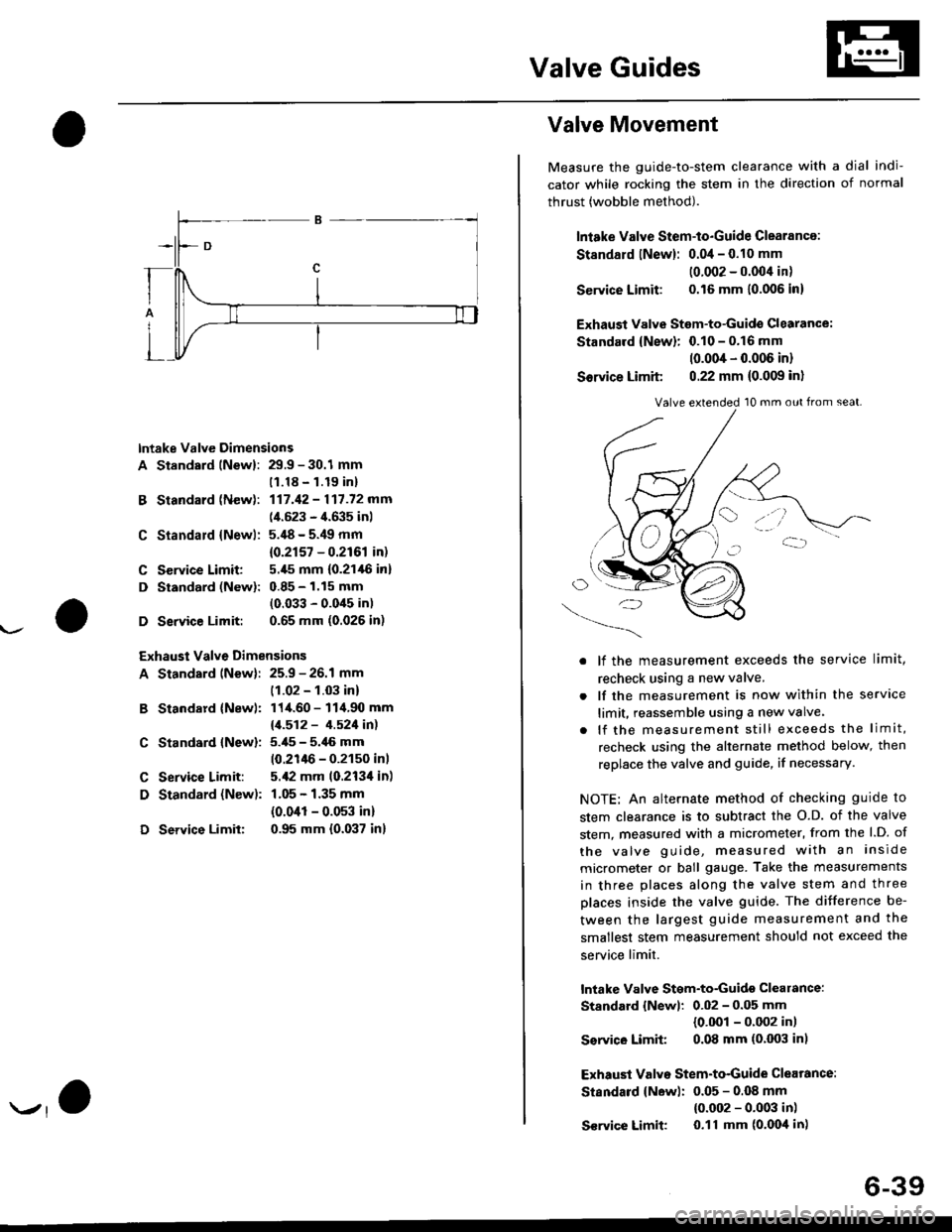
lntake Valve Dimensions
A Standsrd lNewl: 29.9 - 30.1 mm
B Standard (New):
C Standald {Newl:
C Service Limit:
D Standard (New):
D Service Limit:
11.18 - 1.19 inl
117.42 - 117.72 mm
(4.523 - 4.635 inl
5.'18 - 5.49 mm
{0.2r57 - 0.2r61 in)
5.,[5 mm (0.21,16 in]
0.85 - 1.15 mm
(0.033 - 0.0'15 in)
0.65 mm (0.026 in)
Exhaust Valve Dimensions
A Standard lNew): 25.9 - 26.1 mm
B Standard {Newl:
C Standard {New):
C Service Limit:
D Standard {New):
D Service Limit:
(1.02 - 1.03 in)
114.60 - 114.90 mm
11.512 - 4.521in1
5.i[5 - 5.46 mm
10.21lt6 - 0.2150 inl
5.,12 mm 10.213'l in)
1.05 - 1.35 mm
{0.041 - 0.053 in)
0.95 mm {0.037 in}
Valve Movement
Measure the guide-to-stem clearance with a dial indi-
cator while rocking the stem in the direction of normal
thrust (wobble method).
lniake Valve Stem-to-Guide Clearance:
St8ndard lNew): 0.04 - 0.10 mm
10.002 - 0.004 in)
Service Limit: 0.16 mm 10.006 in)
Exhaust Valvs Stem-to-Guide Glearance:
Standard {New}: 0.10 - 0.16 mm
10.004 - 0.006 in)
Sorvice Limit 0.22 mm (0.009 in)
O/'-_)
. lf the measurement exceeds the service limit,
recheck using a new valve.
. lf the measurement is now within the service
limit, reassemble using a new valve.
. lf the measurement still exceeds the limit,
recheck using the alternate method below, then
replace the valve and guide, if necessary.
NOTE: An alternate method of checking guide to
stem clearance is to subtract the O.D. of the valve
stem, measured with a micrometer, from the l.D. of
the valve guide, measured with an inside
micrometer or ball gauge. Take the measurements
in three places along the valve stem and three
places inside the valve guide. The difference be-
tween the largest guide measurement and the
smallest stem measurement should not exceed the
service limit.
lntake Valve Stgm-to-Guidg clearance:
Standard {Newl: 0.02 - 0.05 mm
{0.001 - 0.002 in)
Ssrvico Limit 0.08 mm (0.003 in)
Exhaust Valvo Stem-to-Guide Clearance:
Standard {New): 0.05 - 0.OB mm
{0.002 - 0.003 in)
S€rvice Limit 0.11 mm (o'Ooil in)
Valve extended 10 mm out from seat.
6-39
Page 189 of 2189
Cylinder HeadValve Guides
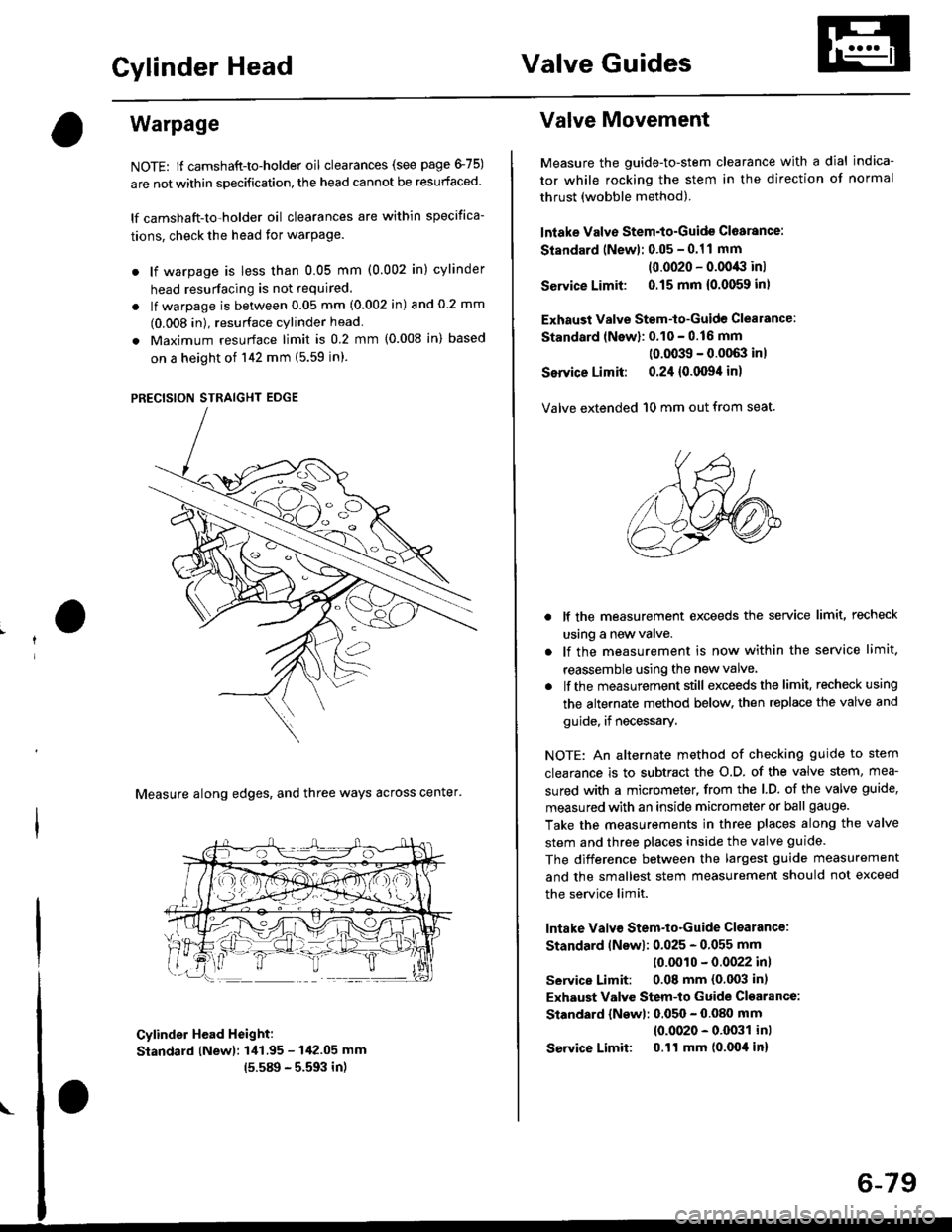
Warpage
NOTE: lf camshaft-to-holder oil clearances (see page 475)
are not within specification, the head cannot be resurfaced.
lf camshaft-to-holder oil clearances are within specifica-
tions, check the head for warPage.
. lf warpage is less than 0.05 mm (0.002 in) cylinder
head resurfacing is not required.
. lf warpage is between 0.05 mm (0.002 in) and 0 2 mm
(0.008 in), resurface cylinder head
. Maximum resurface limit is 0.2 mm (0.008 in) based
on a height of 142 mm (5.59 in).
PRECISION STRAIGHT EDGE
Measure along edges, and three ways across center'
Cylinder Head Height:
Standard lNewl: 1i11.95 - 142.05 mm
15.589 - 5.593 in)
Valve Movement
Measure the guide-to-stem clearance with a dial indica-
tor while rocking the stem in the direction of normal
thrust (wobble method).
lntake Valve Stem-to-Guide Cl6arance:
Standard (Newl: 0.05 - 0.11 mm
(0.0020 - 0.0043 inl
Service Limit: 0.15 mm {0.0059 inl
Exhaust Valve Stem-to-Guide Clealance:
Standard lNewl: 0.10 - 0.16 mm
(0.0039 - 0.0063 inl
Service Limit: 0.24 {0.0094 in)
Valve extended 10 mm out from seat.
lf the measurement exceeds the service limit, recheck
using a new valve.
lf the measurement is now within the service limit.
reassemble using the new valve
lf the measurement still exceeds the limit. recheck using
the alternate method below. then replace the valve and
guide, if necessary.
NOTE: An alternate method of checking guide to stem
clearance is to subtract the o.D. of the valve stem, mea-
sured with a micrometer, from the l.D. of the valve guide,
measured with an inside micrometer or ball gauge.
Take the measurements in three places along the valve
stem and three places inside the valve guide.
The difference between the largest guide measurement
and the smallest stem measurement should not exceed
the service limit.
lntake Valv€ Stem-to-Guide Clsarance:
Standard lNswl: 0.025 - 0.055 mm
10.0010 - 0.0022 inl
service Limit: 0.08 mm (0.003 in)
Exhaust Valve Stem-to Guide Cl€arance:
Standard {Newl: 0.050 - 0.080 mm
{0.0020 - 0.0031 inl
Service Limit 0.ll mm (0.004 in)
6-79
Page 200 of 2189
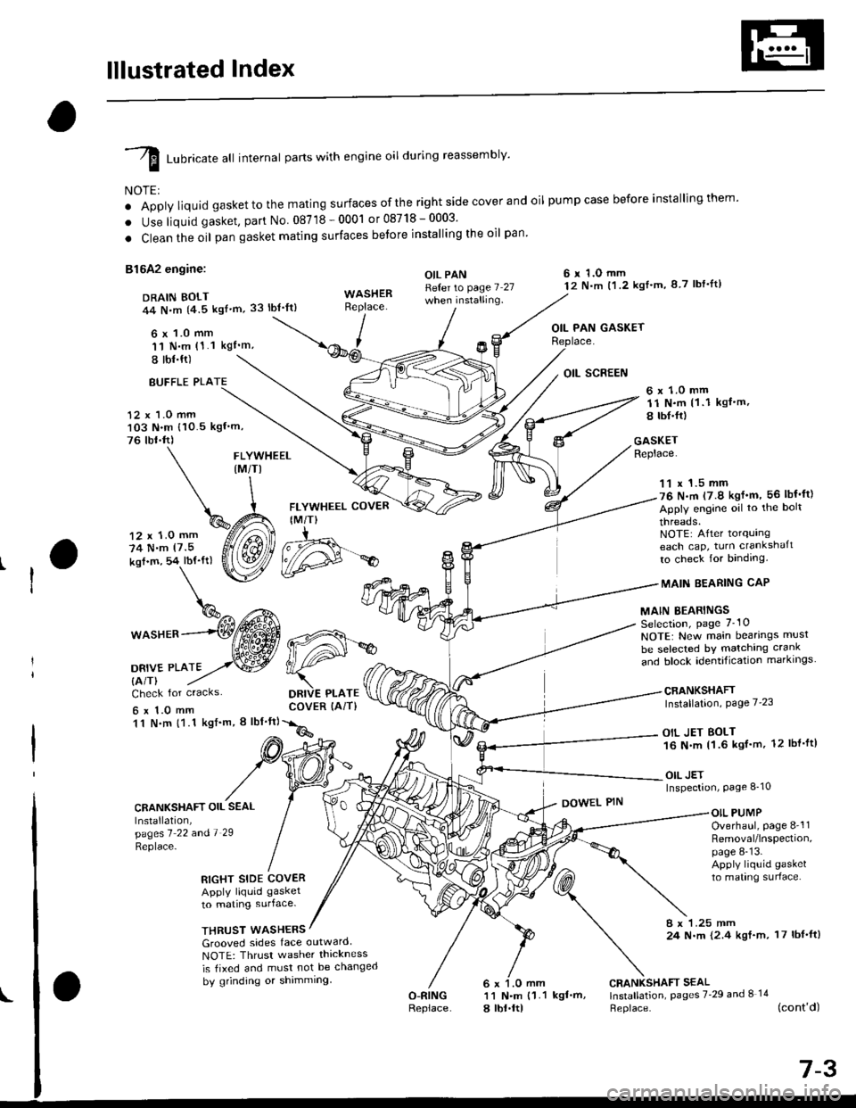
lllustrated Index
I runricate att internal parts with engine oil during reassembly'
NOTE:
o Apply liquid gaskettothe mating surfaces ofthe right side cover and oil pumpcase before installingthem'
. Use liquid gasket, part No 08718-0001 or08718-0003'
. Clean the oil pan gasket mating surfaces betore installing the oil pan
81642 engine:
DRAIN BOLT44 N,m {4.5 kgf'm,33 lbt'ft)
6 x 1.0 mm'11 N.m (1.1 kgI'm,
I tbl.ft)
OIL PANReter to page 7 27when installing.
6 r 1.O mm12 N.m t1.2 kgl'm, 8 7 lbf'lt)
OIL PAN GASKET
BUFFLE PLA
12 x 1.0 mm103 N.m {10.5 kgf'm,
76 tbr.ft)
6 x 1.0 mm11 N.m (1 .1 kgf.m,
8 tbI.fr)
GASKETReplace.FLYWHEEL(M/TI
12 x 1.0 mm
74 N.m (7.5
kof.m, 54 lbf'ft)
1^c{Eb\%^ t*^
*o"rr^--(Wffi
oa*,trto2,.w
FLYWHEEL COVER
IM/T)
DRIVE PLATECOVER (AiT)
11 x 1.5 mm76 N.m (7.9 kgf'm, 56 lbf'ft)
Apply engine oil to the bolt
threads.NOTE: After torqurngeach cap, turn crankshaft
to check for binding.
MAIN EEARING CAP
MAIN BEARINGSSelection, page 7_10
NOTE: New main bearings musl
be selected bY matching crank
and block identification markrngs
CRANKSHAFTInstallation, Page 7'23
OIL JET BOLT16 N.m 11.6 kgf'm, 12 lbl'ft)
OIL JETInspection, Page 8_10
Check for cracks
6x1.0mm11 N.m {1.1 kgf'm, I lbf'ft}
CRANKSHAFT OIL SEAL
Installation,pagesl 22 andl 29
Replace-
DOWEL PINOIL PUMPOverhaul, page 8-'l1Removal/lnspection,page 8-13.Apply liquid gasket
to mating surlace.RIGHT SIDE COVERApply liquid gasket
to mating surface.
THRUST WASHERS8 x 1.25 mm24 N.m {2.4 kgf.m, 17 lbf'ft)Grooved sides face outward
NOTE: Thrusr washer thickness
is tixed and must not be changed
by grinding or shimming
O-RINGReplace
CRANKSHAFT SEAL11 N.m {1.1 kgf'm, lnstallation, pages 7'29 and I 14
a lbt.ltl Heplace. (cont'd)
d#*
Page 201 of 2189

lllustrated Index
(cont'dl
I Luoricate att internal parts with engine oil during reassembly.
NOTE:
' Apply liquid gasket to the mating surfaces ofthe rightside coverand oil pumpcase before installingthem.. Use liquid gasket, part No. 08718 - 0001 or 087,18 _ OOO3.. Clean the oil pan gasket mating surfaces before installing it.
D16Y7 engine:6 x 1.0 mm12 N.m (1.2 kgt.m.8.7 tbf.tr)DRAIN BOLT44 N.m {4.5 kgt.m.33 tbt.ttl
,(
I
I
OIL PAN GASKETFLYWHEEL COVERIM/T)6x 1.0 mm12 N.m ('l .2 kgt.m, 8.7 tbt.trl
OIL PANRefer to page 7-27
Apply liquid gasker tothese points.
Replace.
WASHERReplace.12 x '1.0 mm118 N.m{12.0 kgt.m, 87 tbf.tr}
11 x 1.5 mm51 N.m15.2 kgl.m,38lbtftl
Apply engine oilto the boltthreads.NOTE: After torquingeach cap, turn the crankshaftto check for binding.
MAIN BEARINGSSelection, page 7-10
MAIN BEARING CAP
CRANKSHAFTInstallation, page 7 23
NOTE: New main bearings mustbe selected by matching crankand block identification markings.
6 r 1.0 mm11 N.m {1.1
6 x 1.0 mm11 N.m 11.1
ksI.m, 8 lbt.ft)
OIL SCREEN
kgt.m, 8 lbf.trl
Check for cracks.
CRANKSHAFT OIL SEALInstallation,pages 1 22 a^d 7-29
\:eprace'
GASKETReplace.
6 x 1.O mm11 N.m {1.1 kgt.m,8 rbt.frl
RIGHT SIDE COVERApply liquid gasker1o matrng surface,
OIL PUMPOverhaul, page 8-12Bemoval/lnspection,page 8-13
DOWEL PIN
WASHERSGrooved sides face outward.NOTE: Thrust washer thicknessis fixed and must not be changedby grinding or shimming.
CRANKSHAFT SEAL
l.j"Ji:l"^ pages z.2e --.S)
Replace.
6 x 1.0 mm11 N.m {1.18 tbt.fr)
7-4
BREATHING PORT COVERMOUNT BOLTS6 x 1.0 mm11 N.m {1.1 kgt.m, 8 tbf.fr}Apply liquid gasker tothe boh threads.
DOWEL PIN
Page 202 of 2189

D16Y5, D16Y8 engines:
DRAIN BOLT39 N.m 14.0 kgt'm,
Apply liquid gasket to
these points.
OIL PANRefer to page 7-25
when installing.WASHERReplace.
29 lbl.tt)
\
\^
6 x 1.0 mm q%
P
I
FLYWHEEL COVER(M/T}
12 x 1.0 mm118 N.m(12.0 kgt.m, 87 lbt'ft)
FLYWHEEL (M/TI
t2 N.m 11.2 kgf'm,
8.7 lbl.ftl
11 x 1.5 mm
51 N.m(5.2 kgf'm, 38 lbf ftl
Apply engine oiltothe bolt
threads.NOTE: Aftertorquingeach cap, turn crankshaft
to check for binding.
MAINBEARING
MAIN BEARINGSSelection, page 7-10NOTE: New main bearings must
be selected by matching crank
"nJ lr."i io"irriti"",ion-markings. --------*-i6{\
CRANKSHAFTInstallation, page 7-23
6 r 1.0 mm11 N.m (1 1 kgf'm, I lbf'ttl
OII PAN GASKETReplace.
DRIVE PLATE COVER
{A/T or CVT)
12 r 1.0 mm
74 N.m
17.5 kgl.m, 54 lbf'ft)
DBIVE PLATE {A/T or CVTI
Check for cracks
6 x 1.O mm11 N.m {1.1 kgl'm,
8 tbl.ftl
CRANKSHAFT OIL SEAL
lnstallation,pages 7'?1 and '1 '28
Replace.
RIGHT SIDE COVER
Apply liquid gasket
to mating surface.
OIL SCREEN
GASKETReplace.
OIL PUMPOverhaul, page 8_12Removal/lnspection,page 8-13Apply liquid gasket
to mating surface.
DOWEL PIN
WASHEFS
Grooved sides tace outward
NOTE: Thrust washer thickness
is fixed and must not be changed
bV grinding or shimming.
CRANKSHAFT SEALInstallation, pages 7 29
and 8-14Replace.
BREATHING PORT COVER
MOUNT BOLTS6 x 1.O mm11 f{..n (1.1 kgf'm, 8 lbf'fl)
Apply liquid gasket to
the bolt threads.
O.RINGReplace.
6 x 1.0 mm
11 N.m (1 1 kgl'm,
8 tbr.ftl
(cont'd)
7-5
\
OOWEL PIN