Page 1114 of 1680
Power Distribution
N0.54 (404)FUSE(From page 23 55)
N0.49 (30A)FUSE(From page 23-55)
Gircuit ldentification (cont'dl
UNDER.DASH FUSEi FELAY BOX
(Fuserelay box sockel)Oplional conneclor (+B)
N0.50 (40A) FUSE(From page 23-55)
'/'/H_'GRN ----- rower door tock controt un,tF Halct op€ler acluatorl- Halch lalcn sw,rm
BLKGFN <- BLKRED - Rear window delogger
N0.16 (7.sA) FUSE(Viaswlch)
f7
IBLUfrEL
IGNITION SWITCHlFrom page 23 56)
ft
IWHT/BLK
"^--f,_
(Fus€irglay box soclel)
G201G401
Cigaretle lighler
Oplional conneclor (ACC)
Audro unil conneclorWHT/GRN
23-58
Page 1121 of 1680

I "tl
III
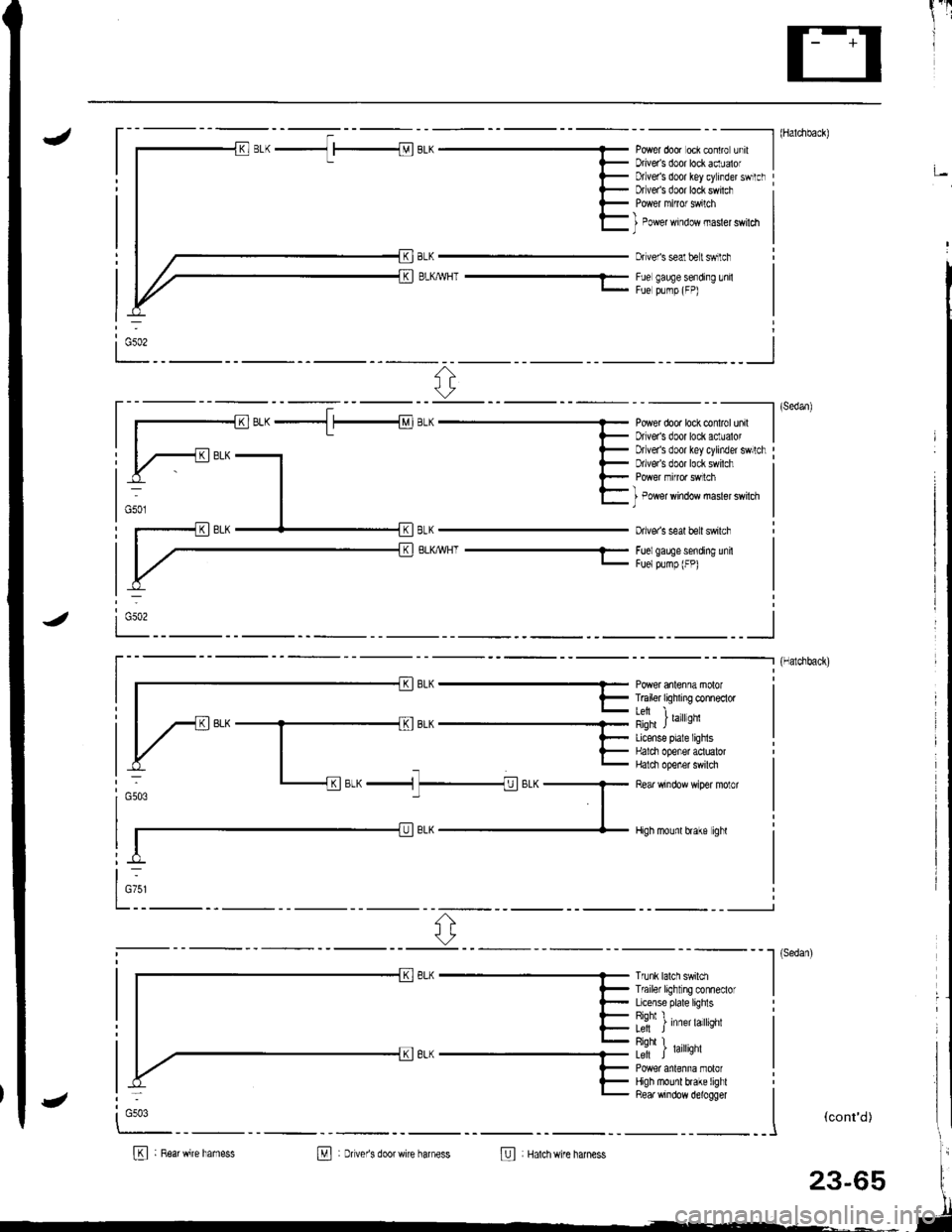
J- - - - --------- l (Haldlback)
Power door oci contro unrt IDriveas door lockaclualof I;Dtlver's door key cylinder swrtclrDfveas door lock swilch
BLKMHT ---1-
I Power window masler swildl)
Dr veis seal belt swilch
Fue gauge sending lnilFue plmp (FP)
ri:
----------l (sedan)
Power dooa lock conlrol unil IDriveas door lock aclualor I
BLKWHT-
Drlver's door key cylinder swllchDrlve/s door lock swilch
I Power window masler swilch)
Dive. s seal beit swilch
Foelgaee sending unitFuelpump (FP)
i Gso2
_ _ _--_______.] {Halchback)
r- || | F T6iler tiqhxng conneclor I
lil i ,",rror,'nqfi JLicense plale lighlsHalci opener aotualorHalci opener swilch
Rear window wiper molor
High mounl hake ighl
otw ^ -n1
t-
l_:1' ^r;-"-1 7_1;.^G503
Trunk lalch swildlTf ailer light ng conneclorLicense plate lighlsRiohl I�L; J Inner larqnr
Riohl I� .Le-ft J raflqnl
High mounl brake lighlRea. window d€logger
I
""*'�
I
(cont'd)
B : R6arwire hamessM : Dver's doorwire harness@ Hatchwire harness
:
G503
23-65
Page 1122 of 1680
Ground Distribution
Circuit ldentification (cont'd)
BLK-lr- | A8S controlunrt
8LK,ryHT - J
i ,., *n
out
E ABssub'hamess
B : Rear wlndow delogger ground wire
I : sRs main hamess
23-66
Page 1125 of 1680
1
I
PowerRelays
RelayTest
JNOTE: See page 23-194 for turn signal/hazard relay
input test.
Normally.open type:
fWC2i
1. Check for continuitv between the terminals.
. There should be continuity between the A and B
terminals when power and ground are connect-
ed to the C and D terminals.
. There should be no continuity between the A
and B terminals when power is disconnected.
<2
F;Z
,,A
/ l'El--E \
ey
Normally-opon type:
'1. Check continuity between relay terminals.
. There should be continuity between the A and C
terminals when power and ground are connect-
ed to the B and D terminals.
o There should be no continuitv when oower is
disconnacted,
o Power window relay
. Radiator fan relay
. Condenser fan relay
. AVC compressor clutch relay
Typel:
c
I Blower motor relay
. Rear window defogger relay
Typel:
Terminal
P";(c5t--__\B
Disconnected
Connectedoo
Terminal
P"*"r(B5-lc
Connectedoo
Disconnected
Page 1167 of 1680
Rectifier Removal
MITSUBISHI:
1. Remove the four through bolts.
3.Separate the rear housing from the drive-end hous-
ing by inserting a flat tip screwdriver into the open-
ings and prying them a part. Be careful not to dam-
age the stator with the tip of the screwdriver.
Separate the rear housing and drive-end
with the stator anached to the rear housinq.
n ousrng
2.Heat the rear bearing seat with a 1,000 W hair drier
for about five minutes (120 - 140'F, 50 - 60'C).
HAIN DRIER
NEAR AEARINGSEAT
STATOR
(cont'd)
FEAR HOUSING
DRIVE.END HOUSIT{G
DRIVE.END HOUSING
REAR HOUSING
)
{
{
)
23-111
t
/-
Page 1168 of 1680

Gharging System
Reetifier Removal (cont'd)
MITSUBISHI:
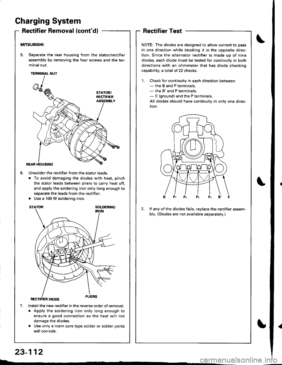
5. Separate the rear housing from the stator/rectifier
assembly by removing the four screws and the ter-
minal nut.
6.
1.
Unsolder the rectifier from the stator leads.
. To avoid damaging the diodes with heat, pinch
the stator leads between pliers to carry heat off,
and apply the soldering iron only long enough to
separate the leads from the rectifier.
. Use a 100 W soldering iron.
Installthe new rectifier in the reverse order of removal.
. Apply the soldering iron only long enough to
ensure a good connection so the heat will not
damage the diodes.
. Use only a rgsin core type solder or solder joints
will cor.ode.
RectifierTest
NOTE: The diodes are designed to allow current to pass
in one direction while blocking it in the opposite direc-
tion. Since the alternator rectifier is made up of nine
diodes, each diode must be tested for continuity in both
directions with an ohmmeter that has diode checkino
capability; a total of 22 checks.
1. Check for continuity in each direction between- the B and P terminals.- the B' and P terminals,- E (ground) and the P terminals.
All diodes should have continuity in only one direc-
uon.
2.lf any of the diodes fails, replace the rectifier assem-
bly. (Diodes are not available separately.)
b.�
23-112
{
Page 1169 of 1680

i'[
Rotor Slip Ring TestAlternator Brush Inspection
Separate the drive-end housing from the rear hous-
ing as described on page 23-l 1 1.
Separate the rear housing from the stator/rectifier
assembly by removing the four screws and the ter-
minal nut from the rear housing (see page 23-111).
Measure the length of the brushes with vernier
calrpers.
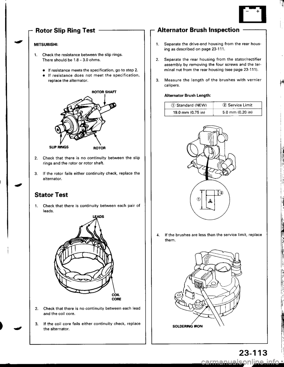
Alternator Brush Length:
O Standard (NEW)O Service Limit
19.0 mm (0.75 in)5.0 mm (0.20 in)
lf the brushes are less than the service limit, replace
them.
23-113
{
J
lFr
MITSUBISHI:
1. Checkthe resistance between the slip rings.
There should be 1.8 - 3.0 ohms.
. lf resistance meets the specification, go to step 2,
. lf resistance does not meet the specification,
replace the alternator.
SLIP RII{GS
Check that there is no continuity between the slip
rings and the rotor or rotor shaft.
lf the rotor fails either continuity check, replace the
alternator.
Stator Test
1. Check that there is continuity between each pair of
leads.
co|LconE
Check that there is no continuity between each
and the coil core.
lf the coil core fails either continuity check, replace
the alternator.
ROIOR SHAFT
J
"-
Page 1170 of 1680

Gharging System
Rear Bearing ReplacementAlternator Reassembly
MITSUBISHI:
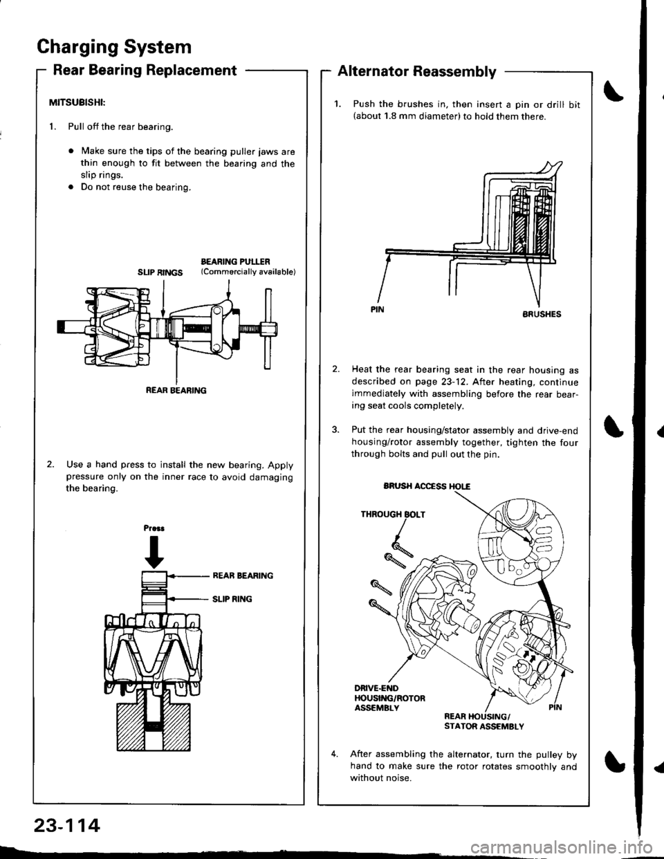
1. Pull off the rear bearing.
Make sure the tips of the bearing puller jaws are
thin enough to fit between the bearing and the
slip rings.
Do not reuse the bearing.
BEARING PULITRSLIPRINGS (Commorciallyav6ilable)
Use a hand press to install the new bearing. Applypressure only on the inner race to avoid damaging
the bearing.
23-114
L : -
REAR BEARING
1.Push the brushes in, then insert a pin or drill bit(about 1.8 mm diameter)to hold them there.
ARUSHES
Heat the rear bearing seat in the rear housing as
described on page 23-12. After heating, continue
immediately with assembling before the rear bear-ing seat cools completely.
Put the rear housing/stator assembly and drive-end
housing/rotor assembly together, tighten the four
through bolts and pull out the pin.
THROUGH BOLT
*,
DRIVE.ENDHOUSI'{G/ROTORASSEMBLYREARSTATOR ASSEMSLY
After assembling the alternator. turn the pulley byhand to make sure the rotor rotates smoothlv and
without noise.
BRUSH AOCCSS HOI,"€