Page 1291 of 1680

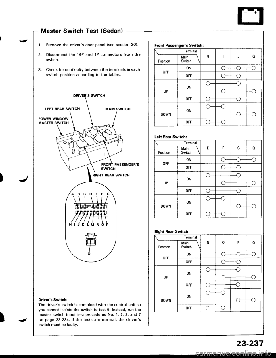
Master Switch Test (Sedanl
't
J)
I
1.Remove the driver's door panel (see section 20).
Disconnect the 16P and 1P connectors from the
switch.
Check Jor continuity between the terminals in each
switch position according to the tables.
,,
s swtTcH
LEFT REAF SWITCHMAIN SWITCH
POWER WINDOWMASTER SWITCH
PASSENGER'SswtTcH
RIGHT REAR SWITCH
Drivsr's Switch:
The driver's switch is combined with the control unit so
vou cannot isolate the switch to test it. Instead, run the
master switch input test procedures No. 1, 2, 3. and 7
on page 23-234. lf the tests are normal, the driver's
switch must be faulty.
Front Passenger's Swltch:
Terminal
JoI uain \Position I Switch \
OFFONG_o--o
OFFG*--o
UPONo---o
o-
OFFo---o
DOWNONo---o
G-_O
OFFG--o
ABCDEFG
HIJKLMNO
L€ft Rear Switch:
Terminal
EFGoI Main \Position I Switch \
OFFONo-o--o
OFFo---o
UPONo---o
--oo-
OFFo---o
DOWNONo---o
o--o
OFFo--o
Right Rear Switch:
Terminal
ooPosirion | 35ii.r \
OFFONG-
OFFo-._,f
UPON.)-]--------{-)1___i----o
OFFo--o
DOWNONc-l
o-
oFF :----o
J
23-237
Page 1293 of 1680
Hatchback:
1. Remove the driver's door panel (see section 20).
2. Disconnecl the 10P connector from the switch.
3. Remove the three mounting screws and the switch.
Sedan:
1. Remove the driver's door panel (see section 20).
2. Disconnect the 16P and 1P connectors from the
swrtcn.
3. Remove the two mounting screws and the switch.
POWER MIRRORswtrcH
scBEws
Master Switch ReplacementPassenger's Window Switch
I-
.J)
I
Replacement
Front:
1 . Remove the passenger's door panel lsee section 20).
2. Disconnect the 5P connector from the switch.
3. Remove the two mounting screws and the switch.
Rear (Sedan);
1. Remove the inner handle (see section 2O).
2. Disconnect the 5P connector from the switch.
3. Remove the two mounting screws and the switch.
wtNDowswrTcH
swtTcH
5P CONNECTOR
IN ER HATOLE
23-239
Page 1294 of 1680

Power Windows
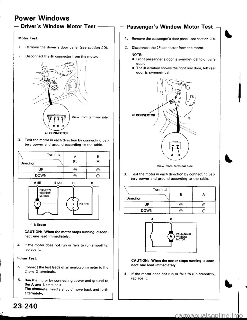
Driver's Window Motor Test
Motor Test:
'1. Remove the driver's door panel (see section 20).
2. Disconnect the 4P connector from the motor.
View from terminal side
4P CONNECTOR
3. Test the motor in each direction by connecting bat-tery power and g.ound according to the table.
CAUTION: When the motor stops running, discon-
nect one lead immediately.
4. lf the motor does not run or fails to run smoothly.
reprace rI.
Pulser Test:
5. Connect the test leads of an analog ohmmeter to the: and D terminals.
6. Run the -noror by connecting power and ground totho A anO 8:errninals.
Thg ohmrneter need e should move back and forthalternately,
1.
2.
Passenger's Window Motor Test
Remove the passenger's door panel {see section 20).
Disconnect the 2P connector from the motor.
NOTE:
a Front passenger's door is symmetricalto driver's
door.
a The illustration shows the right rear door. left rear
door is symmetrical.
2P CONNECTOR
View from terminal side
3. Test the motor in each direction by connecting bat-
tery power and ground according to the table.
CAUTION: When the motol stops running, discon-
nect one lead immediately.
lf the motor does not run or fails to run smoothlv,
reprace rI.
(
I
Terminal
Direction{B)
B
{At
UPo@
DOWN@o
Terminal
O'*"r*-TB
UPo@
DOWN@o
23-240
Page 1295 of 1680

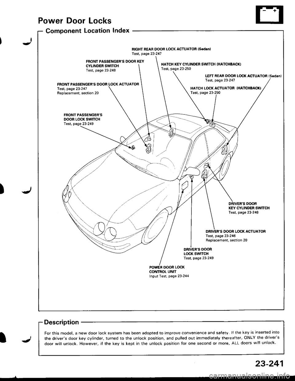
Power Door Locks
Component LocationIndex
RIGHT REAR DOOR LOCK ACTUATOR {SedanlTest, page 23-247
FRONT PASSENGER'S DOOR KEYCYI-INDER SWITCHTest, page 23-248
HATCH KEY CYLINDER SWITCH (HATCHBACK)
Test, page 23-250
LEFT REAR DOOR LOCK ACIUATOR (Scdlnl
Test, page 23'247FRONT PASSENGER'S DOOR LOCK ACTUATORlest, page 23-247Replacement, soction 20HATCH L(rcK ACTUATOR IHATCHBAC(ITest, page 23-250
FRONT PASSENGER'SDOOR LOCK SWITCHTest, page 23-249
DRIVER'S DOORKEY CYLINDER SW]TCHTest, page 23-248
OOOR LOCK ACTUATORTest, page 23-246Replacement, section 20
DRIVEB'S DOORLOCK SWITCHTest, page 23-249
oooR LocKCONTNOL UNITInput Test, page 23-244
-)
J)
I
For this model, a new door lock svstem has been adooted to imDrove convenience and salety. lf the key is inserted into
the driver's door kev cvlinder. turned to the unlock position, and pulled out immediately thereafter, ONLY the driver's
door will unlock. However, il the key is kept in the unlock position for one second or more, ALL doors will unlock.J
23-241
Page 1296 of 1680
Power Door Locks
Circuit Diagram
@*"
DR]VER'S000R LocKSWITCH
NATCN KEYCYLINDER SWITCH
L_____
ooon rocx xroe If7 l
VIKEY
DRIVER'SDOOR LOCKACTUATOR
E
UNDER.HOOO FUSEi RELAY BOX
N0.41 (1004) No.s4 (40A)
DFIVERS DOORKEY CYLJNOERSWITCH
WHT/GRN
FRONTPASSENGERSDOOR LOCKACTUATOR
T--=-l-4{il^
* LEFT REARDOOR LOCKACTUATOR
,@-
* RIGHT NEARDOOR LOCKACTUATOH
-4{.ill^
HATCH LOCKACTUATOR
T-:-lfl.|.{-
LTGRN
LT BLU
A
t--lt=JKEY
i
Atl
T-tl-lKEYBLK
I
G503
.LK BLKll
tlAA
:-l
G501 G2r.G502 ercl
BLK
,l'
G5o1G502
LOCK
o
POWER DOORLOCK CONTROLUNIT
8LK
A-l
G501G502
23-242
Page 1301 of 1680
Passenger's Door Lock Actuator Test
1. Remove the door panel (see section 20).
2. Disconnect the 2P connector from the actuator.
Front Passenger's Door:
lerminal side
ACTUATOR
)J
23-247
Rear Passenger's Door:
NOTE: Left rear actuator is shown, right rear actuator
is similar.
View from lerminal side
Check actuator operation by connecting power and
ground according to the table.
CAUTION: To prevent damage to the actuator, ap-
ply battery voltage only momenta.ily.
;
4. lf the actuator tails to work properly, replace it.
Term inal
Position
B
LOCKo@
UNLOCKoo
Page 1304 of 1680
Power Door Locks
Hatch Lock Actuator Test
Remove the rear t.im panel (see section 20).
Disconnect the 6P connector from the actuator.
1.1.
2.
Hatch Key Cylinder Switch Test
Remove the rear trim panel (see section 20).
Disconnect the 3P connector from the switch.
3. Check for continuitv between the terminals in each
switch position according to the table.
6P CONNECTOR
3. Check actuator operation by connecting power andground according to the table.
CAUTION: To prev€nt damage to the actuator,
apply battery voltage only momeniarily.
1 lf the actuator fails to work properly, replace it,
23-250
Terminal
ilil;---tBc
LOCKoo
UNLOCKo
Terminal
ilil;-]E
LOCK@o
UNLOCKoo
UNLOCK
.-,4
I LOCK
| !J KEY
Page 1305 of 1680
Hatch Opener
Circuit DiagramHatch Latch Switch Test
Remove the rear trim panel lsee section 20).
Disconnect the 6P connector from the switch.
3. Check for continuity between the terminals in each
switch position according to the table.
HATCHOPENEHRELAY
HATCHOPENERACTUATOB
UNDER-HOODFUSE/RELAYBOX
UNDER.DASHFUSE/RELAYBOX
la :llf q ^ll
ELUMHT YEURED
tl
[S-l*0,., f/tl| IoPENEF lt.l I
I ? l'*n'" +_i
tl8LK BLK
tl
tl
tt.:
G503 G503
BATTEFY
(+)
Y
I
-r--t
I I lm,1
uI| )Nov II f. (4oA) |rT '
IWHT/RED
I-r----| )ur II L (2oA) I
IWHTiGRN
fi--l->t_:___J-KEY
Terminal
:- ..- crosrUon-1UNLOCK
LOCK
F
23-251
-----t1< IKEY--,_)
J