Page 1271 of 1680
Circuit Diagram
REARwtNDowDEFOGGERSWITCH
BLK
IIJ
DASH LIGHTSBR CHTNESSCONTROLLER
CN TIONswrTcH
/ 8AT \
T ",7-l
II
II
WNT/BLK + WHT
REARWiNDOWDEFOGGER
BtK/GRN
--lELKGRN BLI(RED
1A
T L-]
ll
tl
tl
tl-l
UNDEF HOOD FUSE/RELAY BOX
No41 (100A) N0.42 (40A)
G201G401G201G40lHatchback:G771Sedan iG503I
23-215
Page 1272 of 1680
Rear Window Defogger
Troubleshooting
NOTEr The numbers in the table show the troubleshootino seouence
Item to be inspected
Symptom
=
o
.9
.E
;
ao
o
s
;!i6
<:
FO
>=
;€9c
';i !
oi
O=
{o
a5
3tr
ta
fu-o
,
OJo)
o
c
'-c
Defogger works, but indicator
light does not go on.BLK/YEL or BLU/YEL
Defogger does not work and
indicator light does not go on.3G201
G401YEL, BLU/YEL or BLK/YEL
Defogger does not work, but
indicator light goes on.123G7 71
G503
BLU/YEL or BLK/YEL
BLK/GRN or BLK/WHT
Operation time is too long or
too short (normal operation time
is 25 minutes).
,]
23-216
Page 1273 of 1680
)
Switch Removal
CAUTION: Be carelul not to damage the heater con-
trol/center air vent.
1. Carefully pry the switch out oI the heater con-
trol/center air vent.
2. Disconnect the 6P connector from the switch.
Remove the indicator bulb (turn the socket 45o
counterclockwise), and remove the illumination bulb.
REAR WINDOWDEFOGGER SWITCH
INDICATOR BULB(o.84 W)
.l
Switch Test
NOTE: Be careful not to damage the heater con-
trol/center air vent.
'1. Carefully pry the switch out of the heater con-
trol/center air vent.
2. Check tor continuity between the terminals accord
ing to the table.
Terminal
pLN-_\BcDEF
PUSHEDo/:\-oo--o
o-
\:./
-o\:/
RELEASEDo-/:\_o
-oo-
\:,/
/:\\:./
I
6P CONNECTOR
REAR WINDOW DEFOGGER SWITCH
23-217
Page 1274 of 1680

Rear Window Defogger
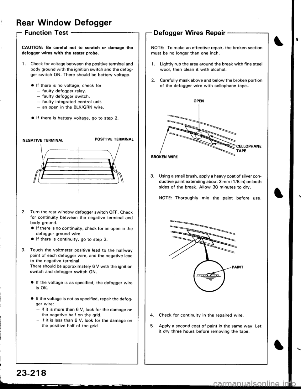
Function TestDefogger Wires Repair
I
I
CAUTION: Be caretul not to scratch or damage the
defogger wires with the tester probe,
1. Check tor voltage between the positive terminal and
body ground with the ignition switch and the defog-
ger switch ON. There should be battery voltage.
lf there is no voltage, check for
faulty defogger relay.- faulty defogger switch.- faulty integrated control unit.- an open in the BLK/GRN wire.
lf there is battery voltage, go to step 2.
NEGATIVE TERMINALPOSITIVE TEFMINAL
2.Turn the rear window defogger switch OFF. Check
for continuity between the negative terminal and
body ground.
a lf there is no continuity, check for an open in the
defogger ground wire.a lf there is continuity, go to step 3.
Touch the voltmeter positive lead to the halfwaypoint of each delogger wire, and the negative lead
to the negative terminal.
There should be approximately 6 V with the ignition
switch and defogger switch ON,
a lf the voltage is as specified, the defogger wire
is OK.
a lf the voltage is not as specified, repair the defog-ger wire:
lf it is more than 6 V, look for the damage on
the negative half on the grid.
lf it is less than 6 V, look for the damage onthe positive half of rhe grid.
3.
NOTE: To make an elfective repair, the broken section
must be no longer than one inch.
1 . Lightly rub the area around the break with fine steel
wool, then clean it with alcohol.
2. Carefully mask above and below the broken portion
of the defogger wire with cellophane tape.
CELLOPHANETAPE
BBOKEN WIRE
3, Using a small brush, apply a heavy coat of silver con-
ductive paint extending about 3 mm (l /8 in) on both
sides of the break. Allow 30 minutes to dry.
NOTE: Thoroughly mix the paint before use.
Check for continuity in the repaired wire.
Apply a second coat of paint in the same way.
it dry three hours before removing the tape.
Let
OPEN
23-214
Page 1284 of 1680
Power Windows
POWER WINDOWMASTER SWITCH(Has built-in control unitiInput Test, page 23-234, 236Iesr, page 23-23'1 ,238Replacement, page 23'239
Component Location Index
UNDER.DASHFUSE/RELAY BOX
DRIVER'STest, page 23-240
LEFT REAR WINDOW MOTOR isedan)Test, page 23 240
POWER WINDOW RELAYTest, page 23-69
LEFT REAR WINDOW SWITCH {Sedan)Test, page 23 238Replacement, page 23 239
FRONT PASSENGER'S WINDOW SWITCHTest, page 23 238Replacement, page 23 239
FRONT PASSENGER'S WINDOW MOTOFTest, page 23-240
RIGHT REAR WINDOW SWITCH (Sedanl
Test, page 23 238Replacement, page 23-239
RIGHT REAR WINOOWMOTOR lsedanlTest, page 23-240
a rrrr'---rnnrn Tl---t----, .----r- L l
(
\
23-230
Page 1285 of 1680
)
Circuit Diagram (Sedan)
RIGHT REAR WINOOWMOTOR
BLK '
LEFT REAR WINOOWMOTOF)
BLUIRED I swrrcH
UNDEF.HOOD FUSE/RELAY BOXUNDEF DASH FUSE/NELAY BOXIGNITION SWITCH
FRONT PASSENGECSWINDOWMOTOR
:. ,:5S rricot !c-:F
23-231
Page 1287 of 1680
Troubleshooting
NOTE: The numbers in the table show the troubleshooting sequence
Item to be inspected
Symptom
;!
-!
z=
9cd)=
-9
3
;
oi
E
dr€
3
3
.=3
;
a
3
E.=3
E
;
;
.zo
E
3
.E3
!
o-
E
!.gi
oi
o-
og
3
c
.q
3
E
B
.gB
B
I
o)
c6z
3
6
N
z
;
6
z
'
6
N
F
z
B
@
All windows do not work.
12
G201
G401
G 501
G502
BLK/YEL
WHT/RED
Driver's window does not
work.25WHT/YEL
Driver's window does not
work in AUTO.23BLU,
BLK/WHT
Passenger's
windows do
not work.
Right front125BLU/BLK
*Left rear145GRN/BLK
*Right rear'lt?45YEL/BLK
*: Sedan
23-233
)t
Page 1289 of 1680

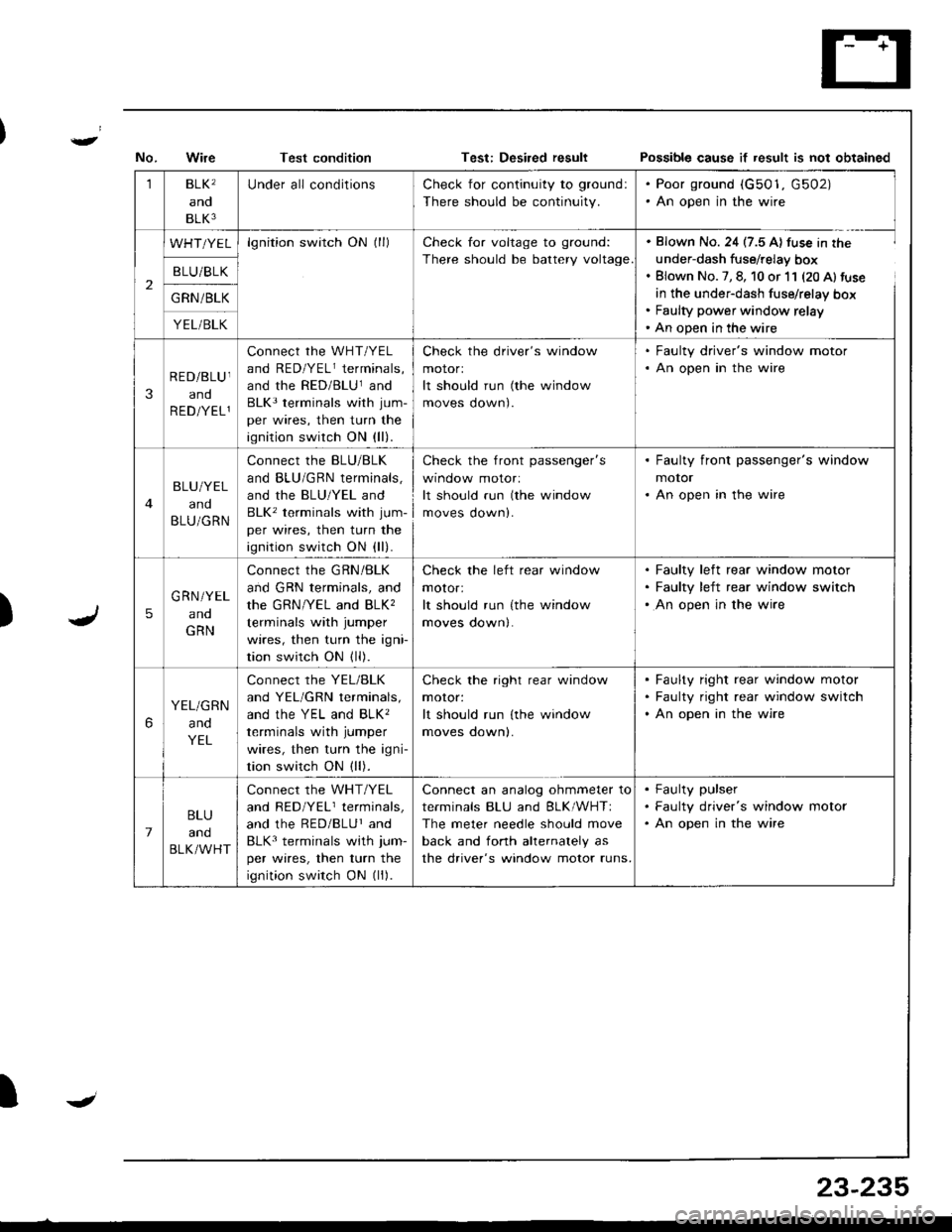
Test conditionPo$sible cause if result is not obtained
)
1BLK'
and
BLK3
Under all conditionsCheck for continuity to ground:
There should be continuity.
. Poor ground (G501, G502). An open in the wire
2
WHT/YELlgnition switch ON (ll)Check for voltage to ground:
There should be battery voltage
. Blown No. 24 (7.5 A) fuse in the
under-dash fuse/relay box. Blown No. 7, 8, 10 or 11 (20 Al fuse
in the under-dash fuse/relay box. Faulty power window relay' An open in the wire
B LU/BLK
G RN /BLK
YEL/BLK
3
RED/BLU I
and
R ED/YEL1
connect rhe wHT/YEL
and RED/YELr terminals,
and the RED/BLUland
BLK3 terminals with jum-
per wires, then turn the
ignition switch ON (ll).
Check the driver's window
motorl
It should run (the window
moves oown).
. Faulty driver's window motor. An open in the wire
BLU/YEL
and
BLU/GRN
Connect the BLU/BLK
and BLU/GRN terminals,
and the BLU/YEL and
BLK' terminals with jum-
per wires, then turn the
ignition switch ON (ll).
check the front passenger's
wtnoow molor:
It should run (the window
moves down).
. Faulty front passenger's window
motor. An open in the wire
5
G RN/YEL
ano
GRN
Connect the GRN/BLK
and GRN terminals, and
the GRN/YEL and BLK,
terminals with jumper
wires, then turn the igni
tion switch ON (ll).
Check the left rear window
motor:
It should run {the window
moves down|.
Faulty left rear window motor
Faulty left rear window switch
An open in the wire
6
YEL/GRN
and
YEL
Connect the YEL/BLK
and YEL/GRN terminals,
ANd thc YEL ANd BLK'
terminals with jumper
wires, then turn the igni-
tion switch ON (ll).
Check the right rear window
moror:
It should run lthe window
moves oownl.
Faulty right rear window motor
Faulty right rear window switch
An open in the wire
7
BLU
and
BLK/WHT
Connect the WHT/YEL
and RED/YELr terminals,
and the RED/BLUr and
BLK3 terminals with jum-
per wires, then turn the
ignition switch ON (ll).
Connect an analog ohmmeter to
terminals BLU and BLK/WHTI
The meter needle should move
back and fonh ahernalely as
the driver's window motor runs.
Faulty pulser
Faulty driver's window motor
An open in the wire
IJ
23-235