Page 1232 of 1680
Taillights (Sedanl
Bulb Replacement
Taillight:'1. Open the trunk lid, then remove the rear panel lin-
ing and side lining (see section 20).
2. Remove the bulb from the bulb socket.
O: BRAKE/TAILLIGHT BULB 132/3 CPI
@; TURN SIGNAL LIGHT BULB (32 CP)
@: REAR PARKING LIGHT EULB (3 CP)
23-176
Inn€r Taillight:'1. Open the trunk lid, then remove the bulb housing,
2. Remove the bulb from the bulb housing.
BACK.UP LIGHT BULB (32 CP}
BRAKE/TAILLIGHT BULB {32l3 CP)
O:
/n.
EULB HOUSING
Page 1234 of 1680
Dash Lights Brightness Control
Circuit Diagram
UNDER-HOOO FUSgRELAY 8OXUNDEN.DASHFUSE/RELAYEOXtX"f -.------^-;^*;;ilLrcrTswrc.
ffiwHT-lf-FEDGaN
, &TGEAN POSITION INOICATOROIMMING CIFCUIT.ATTGEAB POSITION CONSOLE LIGHT
. CRUISE COI,{TROL DIMMING CIRCUIT.CRUISE CONTHOT MAIN SWITCH LIGHT.GAUGE LIGHTS.HAZAFDWABN NG SWITCH LIGHT. HEATER CONTROL PANEL LIGHTS. REAR WINDOW DEFOGGER SWITCH LIGHT
23-178
Page 1247 of 1680
High Mount Brake Light Replacement (Bulb type)
Hatchback:Sedan:
1.Open the hatch.
Remove the two clips and the cover.
Remove the two nuts and the high mount brakelight, then disconnect the 2P connecror.
1.Open the trunk lid, and disconnect the 2P connector
from the high mount brake light.
Remove the two nuts, then remove the high mount
brake light from the rear shelt.
2.
3.
2.
2P CONNECTOR
Turn the socket 45o counterclockwise to remove the
bulb.
Install the high mount brake light in the reverse or-
der of removal, and clean the rear window glass be-
tore installing.
CAUTION: When installing the high mount brake
light, make sure the rubber seal fits against the reai
window evenly.
3.Install the high mount brake light in the reverse or
der of removal. Clean the rear window qlass belore
installing the light.
5.
)
23-191
Page 1252 of 1680
Stereo Sound System
Component Location Index
DOORSPEAKERReplacement, page 23-2OO
NOTE: The original radio has a coded theft protection
circuit. Be sure to get the customer's code number betore- disconnecting the battery.- removing the No.47 (7.5 A) fuse from the under-
hood fuse/relay box.- removing the radio.
After service, reconnect power to the radio and turn it
on. When the word "CODE" is displayed, enter the cus-
tomer's 5 digit code to restore radio operation.
STEREO RADIO/CASSETTEPLAYERRemoval, page 23-199Terminals, page 23 200
RIGHT TWEETERReplacement, page 23'200
BIGHT REARSPEAKERReplacement, page 23-201
LEFT REARSPEAKERReplacement, page 23,201POWER ANTENNA MOTORTest, page 23-202Replacernent, page 23-203
23-196
Page 1254 of 1680
Stereo Sound System
Circuit Diagram
WHT/RED
tWHTi RED
UNDER.HOOD FUSE / RELAY BOX
UNDER.DASHFUSE/RELAYBOX
N0.30 (7.5A)FUSE
f7
IRED/BLK
UNDER,DASHFUSE/RELAYBOX
FRONTPASSENGER'SoooRSPEAKER
ANTENNA MAST
LEFTREABSPEAKER
RIGHTREARSPEAKEB
rna-ll
-ttl
;\\:/
o=4-ll
-{tl
x!\:/
ANTENNA LEAD
BLU,YEL
GRY/rrVHT
REO/YEL
ERNMHT
POWER ANTENNA MOTOR{wilh lhe antenna reraded lully)
BLK
I
G551
8LK
I
G503
No 4l (100A) No 42 (40A)
rc\RED/GRN VSTEBEO RADIOiCASSETTE PLAYER
23-198
Page 1256 of 1680

Stereo
Stereo
Sound System
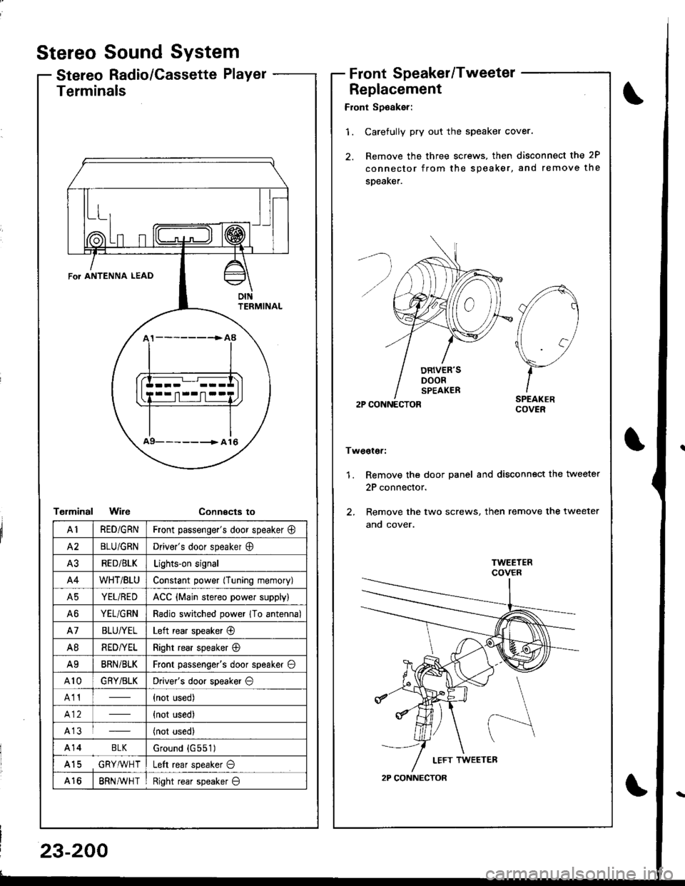
Radio/Cassette PlayerFrontSpeaker/Tweeter
Replacement
Front Sp€aker:
'1. Carefully pry out the speaker cover.
2. Remove the three screws, then disconnect the 2P
connector from the speaker, and remove the
speaKer.
2P CONNECTOR
Tweoter:
1. Remove the door panel and disconn€ct the tweeter
2P connector.
2. Remove the two screws, then remove the tweeter
ano cover.
A
//1
\7
)-ISPEAKERCOVER
2P CONNECTOR
Terminals
T€rminalWireConnecta to
\
FoT ANTENNA LEAD
oIttFRMINAL
a9- -- -------> A 16
AIRED/GRNFront passenge.'s door speaker @
A2BLU/GRNDriver's door speaker O
A3RED/BLKLights-on signal
A4WHT/BtUConstant power (Tuning memory)
A5YEL/REDACC {Main stereo power supply)
A6YEL/GRNRadio switched power 1To antenna)
A7BLU/YELLeft rear speaker @
A8RED/YELRight rear speaker @
A9BRNi BLKFront passenger's door speaker O
A10GRY/BLKDriver's door speaker O
A11(not used)
{not used)
A13(not used)
A14 BLKGround {G551)
A15 GRY,ryVHTLeft rear speaker O
A168RN AVH TRight rear speaker O
23-200
Page 1257 of 1680
Rear Speaker Replacement
Hatchback:
l. Remove the speaker cover.
2. Remove the three screws, then disconnect the 2P
connector from the rear speaker.
Sedan:
1, Remove the three screws trom the trunk side, then
femove the speaker cover.
2. Remove the four screws, then disconnect the 2P
connector from the speaker, and remove the
speaker.
LEFT REARSPEAKER
OUARTER
IIz>- |
TRIM PANEL
I.EFT REARSPEAKER
2P CONNECTOB
2P CONNECTOR
SPEAKER COVER
REAR TRAY
SPEAKER COVES
)
I
23-201
Page 1270 of 1680
Rear Window Defogger
Component Location Index
Description
The rear window de{ogger is controlled by the integrated control unit. Pushing the detogger switch in the Instrumentpanel sends a signal to the defogger timer in the integrated control unit, and the defogger stays on for 25 minutes oruntil the ignition switch is turned off. The indicator light in the switch comes on when the defogger works.
UNDER.OASH FUSE/RELAY BOX
r-'luijij u lNEAR WINDOWDEFOGGER SWITCHRemoval, page 23-217Test, page 23 217
REARDEFOGGERREI-AYTest, page 23-69
23-214