Page 1187 of 1680
)
{
t.t
t.!
23-131
Fuel Gauge
Gauge Test
NOTE: Refer to page 23-123 for the fuel gauge system
circuit.
1. Check the No. 25 (7.5 A) fuse in the under-dash
fuse/relay box before testing.
2. Remove the rear seat (see section 20).
Remove the protective cover and access panel from
the tloor.
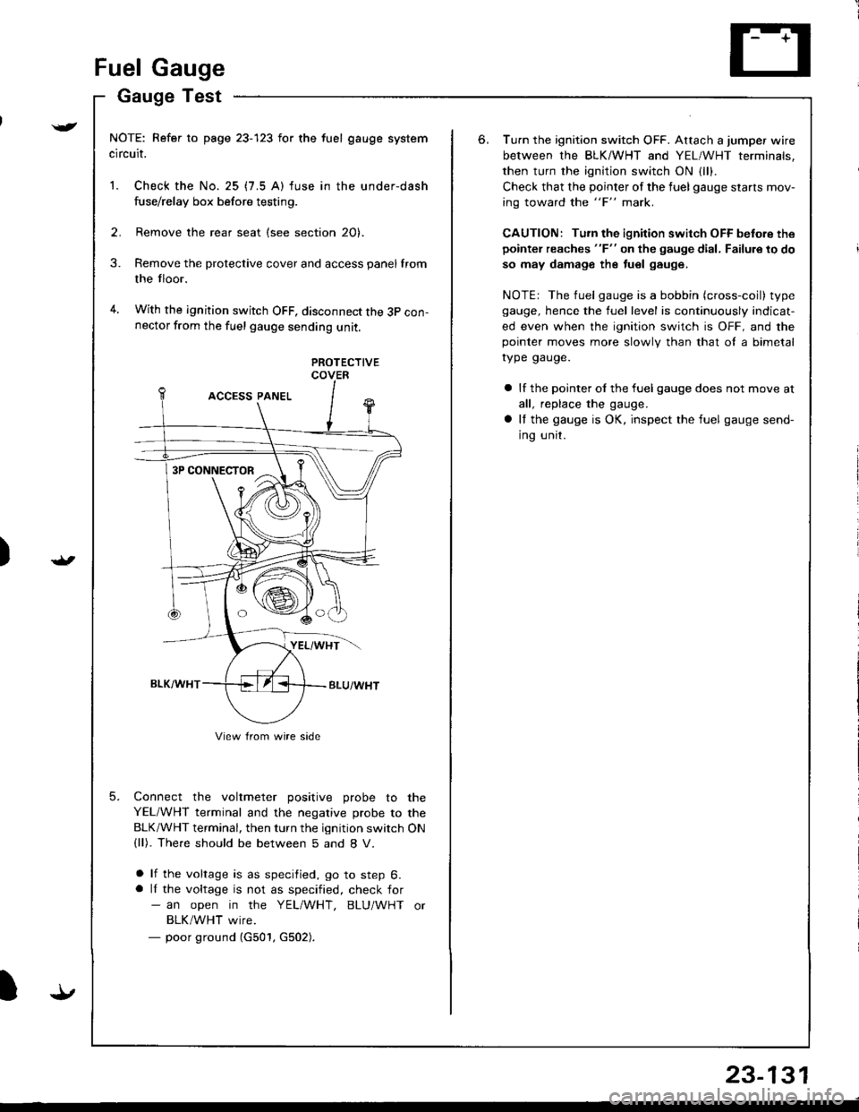
With the ignition switch OFF, disconnect the 3p con-nector from the fuel gauge sending unit.
3.
4.
5.
PROTECTIVECOVER
Connect the voltmeter positive probe to the
YEL/WHT terminal and the negative probe to the
BLK/WHT terminal, then turn the ignition switch ON(ll). The.e should be between 5 and 8 V.
a lf the voltage is as specified, go to step 6.a lI the voltage is not as specified, check for- an open in the YEL/WHT, BLU/WHT or
BLK/WHT wire.- poor ground (G501, G502).
3P CONNECTOR
View from wire side
6.Turn the ignition switch OFF. Attach a jumper wire
between the BLKMHT and YEL/WHT terminals,
then turn the ignition switch ON {1.,.
Check that the pointer of the fuel gauge starls mov-
ing toward the "F" mark.
CAUTION: Turn the ignition switch OFF before the
pointer reaches "F" on the gauge dial, Failure to do
so may damage the tuel gauge.
NOTE: The fuel gauge is a bobbin (cross-coil) type
gauge, hence the fuel level is continuously indicat-
ed even when the ignition switch is OFF, and thepointer moves more slowlv than that ol a bimetal
rype gauge.
a lf the pointer ol the fuel gauge does not move at
all, replace the gauge.
a It the gauge is OK, inspect the fuel gauge send-
ing unit.
Page 1188 of 1680
Fuel Gauge
Sending Unit Test/Replacement
@oo not smoke while working on tha fu6l
system. Keep open llames away trom youl work alea.
1. Remove the rear seat {see section 2O}.
2. Remove the protective cover and access panel trom
the floor.
3. With the ignition switch OFF, disconnect the 3P con-
nector from the fuel gauge sending unit.
4. Remove the fuel gauge sending unit.
o
23-132
Float PositionE1t2F
Resistance (Ol105 - 1 1025.5 39.525
5. lreasure the resistance between the A and B termi-
nals at E (empty), l/2(half full) andF{full} bymov-
ing the tloat.
6. Check the change in resistance by moving the float
uo and down.
(
1.lf unable to obtain the above readings or if resistance
does not change, replace the fuel gauge sending unit.
NOTE: Use new O-rings or packings when reassem-
bling. For details, refer to section 1 1.
Page 1207 of 1680
Shift Lock Solenoid Test/Beplacement
)
r-
)
2.
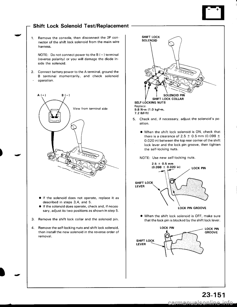
1.Remove the console, then disconnect the 2P con-
nector of the shift lock solenoid trom the main wire
harness.
NOTE: Do not connect power to the B (- ) terminal
(reverse polarity) or you will damage the diode in-
side the solenoid.
Connect battery power to the A terminal, ground the
B terminal momentarily, and check solenoid
operation.
a lf the solenoid does not operate, replace it as
described in steps 3,4, and 5.
a lf the solenoid does operate, check and, i{ neces
sary, adjust its two positions as shown in step 5.
3. Remove the shift lock collar and the solenoid pin.
4. Remove the selfiocking nuts and shift lock solenoid,
then installthe new solenoid in the reverse order of
removal.
SHIFT LOCKSOLENOID
SHIFT LOCK COLLARSELF-LNUTSReplace.9.8 N.m {1.0 kgf.m,7.2 lbI.Ir)
5. Check and, if necessary, adiust the solenoid's po
sition.
a When the shift lock solenoid is ON, check that
there is a clearance of 2.5 ! O.5 mm {0.098 t
O.020 in) between the top rear corner oI the shilt
lock lever and the lock pin groove, then tighten
the self-locking nuts.
NOTE: Use new self-locking nuts.
2.5 t O.5 mm(0.098 I 0.020 in)
SHIFTLEVERLOCK
LOCK PIN GROOVE
a When the shift lock solenoid is OFF, make sure
that the lock pin is blocked by the shitt lock lever.
LOCK PINGROOVE
LOCK PIN
23-151
Page 1208 of 1680
Integrated Control Unit
Circuit Diagram
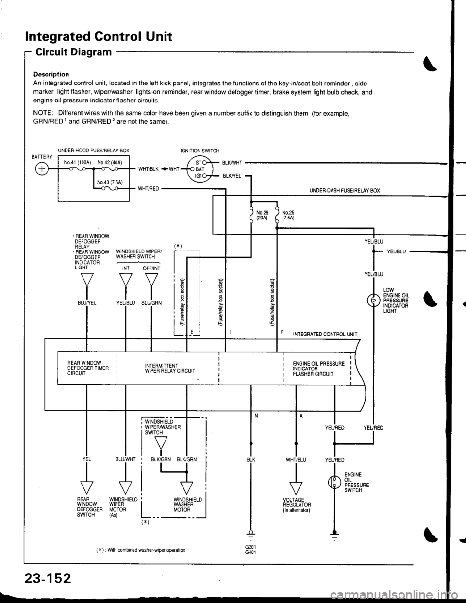
Description
An integrated control unit, located in lhe left kick panel, integrates the lunctions of the key-in/seat belt r€minder , side
marker light llasher, wiper/washer, lights-on reminder, rear window delogger timer, brake system light bulb check, and
engine oil pressure indicator flasher circuits.
NOTE: Different wires with the same color have been given a nu mber suflix to distinguish them (for example,
GRN/RED I and GRN/RED'� are not the same).
REAR WINDOWDEFOGGERRELAYREAF WINDOWDEFOGGENIND CATORL GHT
f-7
IIBLU/YEL
WHT/ BLK
WHT/ REO
+WHT
WNDSHIELDWIPERiWASHER SWITCH
INT OFF/INT
f7 f7
tltlYEUBLU 8LU/GRN
BLUMHT
J
wtN0sHr€10WIPERMOTOR
UNDER.DASH FUSARETAY BOX
F rmecnlleo counoL ultr
YEUBLU
rYEUBLU
YEUREO YEUREO
tl
IYEURED
LOWENGINEOIIPRESSUREINOICATOBLIGHT
; WINDSHIELD' WIPERMASHERI swlTcH
tf7IVtlYEL
J
FEARwtN00wOEFOGGERSWITCH
WHTIBLU
J
VOTTAGEREGULATOR(ln allernatol)
BLK
G441
ENGINEolLPRESSUREswrTcH
UNDER-NOOO FUSE/RELAY BOX
1.6
:6
t;t-L
i
"'i'- 'i*-
|
I Il
I vi: WINDSHIELO II WASHEB I
L__ "oto: _ __l(*)
n
s
s
,]
23-152
(*) :Wilh combined washer-wiper operalion
Page 1211 of 1680
A B C D *E F G
YEL/BLU
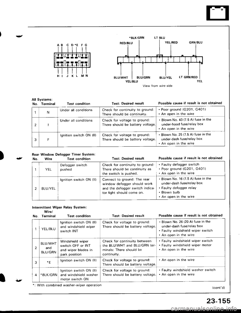
View from wire side
All Systems:
No. TerminalTest condition
Rear Window Defogger Timel System:
No. WireTest condition
Test: Desired resultPossible cause if result is not obtained
Test: Desired resultPossible cause it lesult is not obtained
Test: Desired resultPossible cause if result is not obtained
(cont'd)
)
Inte.mittent Wiper Relay System:
Wire/
No. TerminalTest condition
*BLK/GRN
1NUnder all conditionsCheck for continuity to ground:
There should be continuity.
. Poor ground (G201, G401). An open in the wire
2
Under all conditionsCheck Jor voltage to groundl
There should be battery voltage
. Blown No. 43 (7.5 A) fuse in the
under hood fuse/relay box
'An open in the wire
3F
lgnition switch ON (ll)Check for voltage to ground:
There should be battery voltage.
. Blown No. 25 (7.5 A) fuse in the
under dash fuse/relay box
. An open in the wire
1YEL
Delogger switch
pusneo
Check for continuity to ground:
There should be continuity as
the switch is pushed.
Faulty defogger switch
Poor ground (G201, G401 )
An open in the wire
2BLU/YEL
lgnition switch ON (ll)Connect to groundr The rear
window defogger should work
and the defogger switch indica
tor light should come on.
Blown No. 16 (7.5 A) fuse in the
under-dash fuse/relay box
Faulty delogger relay
Blown bulb
An open in the wire
YEL/BLU
lgnition switch ON (ll)
and windshield wiper
switch INT
Check lor voltage to ground:
There should be battery voltage
Blown No.26 (20 Ai fuse in the
under-dash fuse/relay box
Faulty windshield wiper switch
An open in the wire
2
BLU/WHT
and
BLU/GRN
Windshield wiper
switch OFF or INT
and wiper blades in
park position
Check for continuity between
the BLU/WHT and BLU/GRN ter
minals: There should be
contrnurty.
Faulty windshield wiper switch
Faulty windshield wiper motor
An open in the wire
3lgnition switch ON (ll)Check lor voltage to ground:
There should be battery voltage
An open in the wire
*BLK/GRNlgnition switch ON (ll)
and windshield washer
motor switch ON
Check lor voltage to ground:
There should be battery voltage.
Faulty windshield washer switch
An open in the ware
v*: With combined washer-wiper oDeration
23-155
Page 1226 of 1680
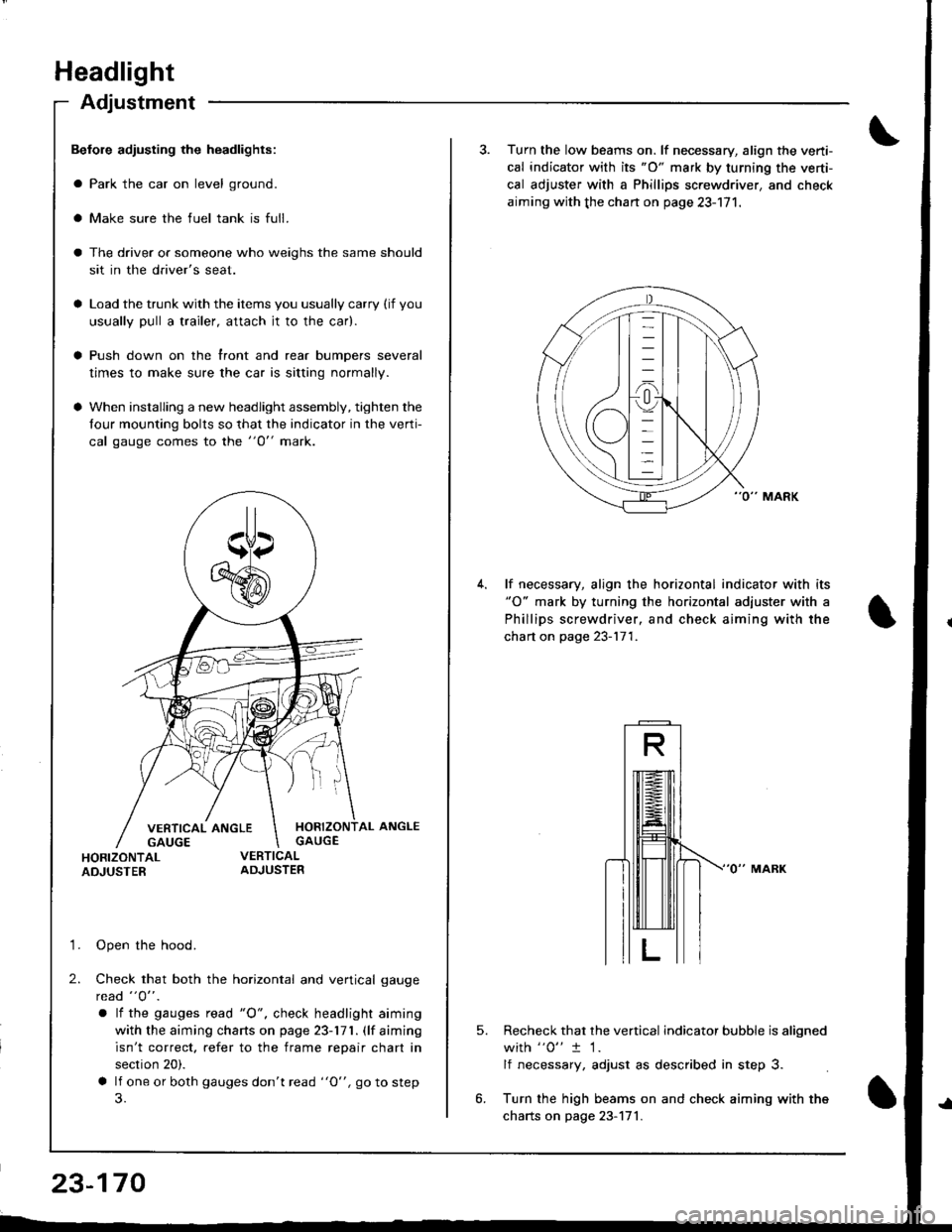
Headlight
Adjustment
Befole adiusting the headlights:
a Park the car on level ground.
a Make sure the fuel tank is full.
The driver or someone who weighs the same should
sit in the driver's seat.
Load the trunk with the items you usually carry (if you
usually pull a trailer, attach jt to the car).
Push down on the front and rear bumpers several
times to make sure the car is sitting normally.
When installing a new headlight assembly, tighten the
four mounting bolts so that the indicator in the verti-
cal gauge comes to the "O" mark.
HORIZONTAL ANGLEGAUGE
HORIZONTALADJUSTER
'1. Open the hood.
2. Check that both the horizontal and vertical gauge
rcad "O" .
a lf the gauges tead "O", check headlight aiming
with the aiming charts on page 23-171. (lf aiming
isn't correct. refer to the frame repair chart in
section 20).
a lf one or both gauges don't read "O", go to step
23-170
3. Turn the low beams on. lf necessary, align the verti-
cal indicator with its "O" mark by turning the verti-
cal adjuster with a Phillips screwdriver, and check
aiming with the chan on page 23-171.
lf necessary, align the horizontal indicator with its"O" mark by turning the horizontal adjuster with a
Phillips screwdriver, and check aiming with the
chart on page 23-171.
5.Recheck that the vertical indicator bubble is aligned
with "0" t 1.
lf necessary, adjust as described in step 3.
Turn the high beams on and check aiming with the
charts on page 23-171.
Page 1230 of 1680
Taillights (Hatchback)
Replacement
1.
2.
Open the rear hatch.
Remove the rear panel lining and the side lining (see
section 20).
Disconnect the 5P connector from the taillight.
Remove the six mounting nuts, then pull out the
taillight.
NOTE:
a lnspect the gasket. Replace it if it is distorted or
stays compressed.
a After installation, run water over the lights to
make sure they don't leak.
6P CONNECTOR
Replacement
Rear turn signal/Rear parking lighis.
1 . Open the rear hatch, then remove the access panel.
2. Remove the bulb from the bulb socket.
O: REAR TURN SIGNAL LIGHT BULB (32 CP)
@: REAR PARKING LIGHT BULB {3 CP)
Brake/Taillighr/Back-up lights:
1. Open the rear hatch.
2. Remove the rear panel lining {see section 20).
(i): BACK-UP LIGHT BULB (32 CF,
(Dr BRAKE/TAILLIGHT BULB (32/3 CP)
ACCESS PANEL
23-174
----
Page 1231 of 1680
I
I
1..,
23-175
Taillights (Sedan)
Replacement
Taillight:'1 . Open the trunk lid, then remove the rear panel lin-
ing and side lining (see section 20).
2. Disconnect the 4P connector from the inner taillight.
3. Remove the four mounting nuts, then pull out the
taillight.
Inner Taillight:
1. Open the trunk lid.
2.
3.
Disconnect the 4P connector from the taillight.
Remove the lour mounting nuts, then pull out the
inner taillight.
NOTE:
a lnspect the gasket. Replace it if it is distorted or stays
compresseo.
a Alter installation, run water over the lights to make
sure they don't leak.
INNER TAILLIGHT
4P CONNECTOR
:-)
TAILLIGHT