Page 981 of 1680
,'t
il
ii
II
APPLICATIONTAPEDOHC VTEC (GSR'
Special Edition {USA LS-S)EMBLEM
REAR TURNSIGNAL LIGHT
APPLICATIONTAPEOUTERTAILLIGHT
J
Emblems
lnstallation
Align the application tape with the rear turn signal light and the gap between the taillight and body, as shown, then press
the emblem into place. Remove the application tape.
NOTE:
a Before applying, clean the body surlace with a sponge dampened in alcohol.
a Atter cleaning, keep oil, grease and water trom getting on the surface.
a When applying, make sure there are no wrinkles in the rear emblem
Attachment Point:
Hatchback
REAR TURNSIGNAL LIGHT
DOHC VTEC {GSR)/sDecial Edition lUsa Ls-s)EMBLEM
20-167
Page 982 of 1680
Emblem
Installation (cont'dl
Type R Mod€l:
Align the rear emblem application tape with the reaf turn signal light and the gap between the taillight and body, asshown, then press the emblem into place. Remove the application tape.
Align the side emblem application tape with the body line and the wheelwell opening, as shown, then press the embleminto place, Remove the application tape.
NOTE:
. Before applying. clean the body surface with a sponge dampened in alcohol.. After cleaning, keep oil, grease and water from getting on the surface.. When applying, make sure there are no wrinkles in the rear emblem.
Attachment Point:
i
l
TYPE RREAR EMBLEM
Align with the rear turnsagnal light.
TYPE RSIDE EMBLEM
TYPE R
BOOY UNE
20-168
TAILLIGHT
Page 983 of 1680
Sub-frame Torque Sequence:
CAUTION: Atter loosening the lea. beam mounting bolts. be sure to replace them with new ones.
6 x 1,0 mm9.8 N m (1.0 kgf m,7.2 rbf.ft)REAB BEAM BRACE
REAR BEAMCOLLAR
'10 x 1.25 mm44 N.m (4.5 kgl.m.33 tbf.ft)
REAR BEAM
REAR BEAM14 x 1.5 mm89 N m {9.1 kgf m.66 tbt.frlReplace.
Sub-frame
20-169
Page 1011 of 1680
Heater Control Panel
Replacement
J
2.
1.Disconnect the air mix control cable from the heat
er unit (see page 21-27).
Remove the rear window delogger switch and the
hazard warning switch.
Remove the two self-tapping screws, then pull out
the heater control panel and the center air vent. Dis-
connect the connectors, and remove the heater con-
trol panel and the center air vent.
NOTE: The locking tabs of the hazard warning
switch and heater control panel connectors are on
the bottom.
CENTER AIR VENTREAR WINDOWD€FOGGERswtrcH
HAZARDWARNINGswrTcH
CONNECTORS
4. Remove the four self-tapping screws and the center
atr vent.
Install in the reverse order of removal, and adjust the
air mix control cable at the heater unit (see page
21-271.lt necessary, adjust the heater valve cable
lsee page 21-27).
5.
AIR MIX CONTROL CABLE
CENTER AIR VENT
21-25
Page 1069 of 1680

Connector ldentification and Wire Harness Routing
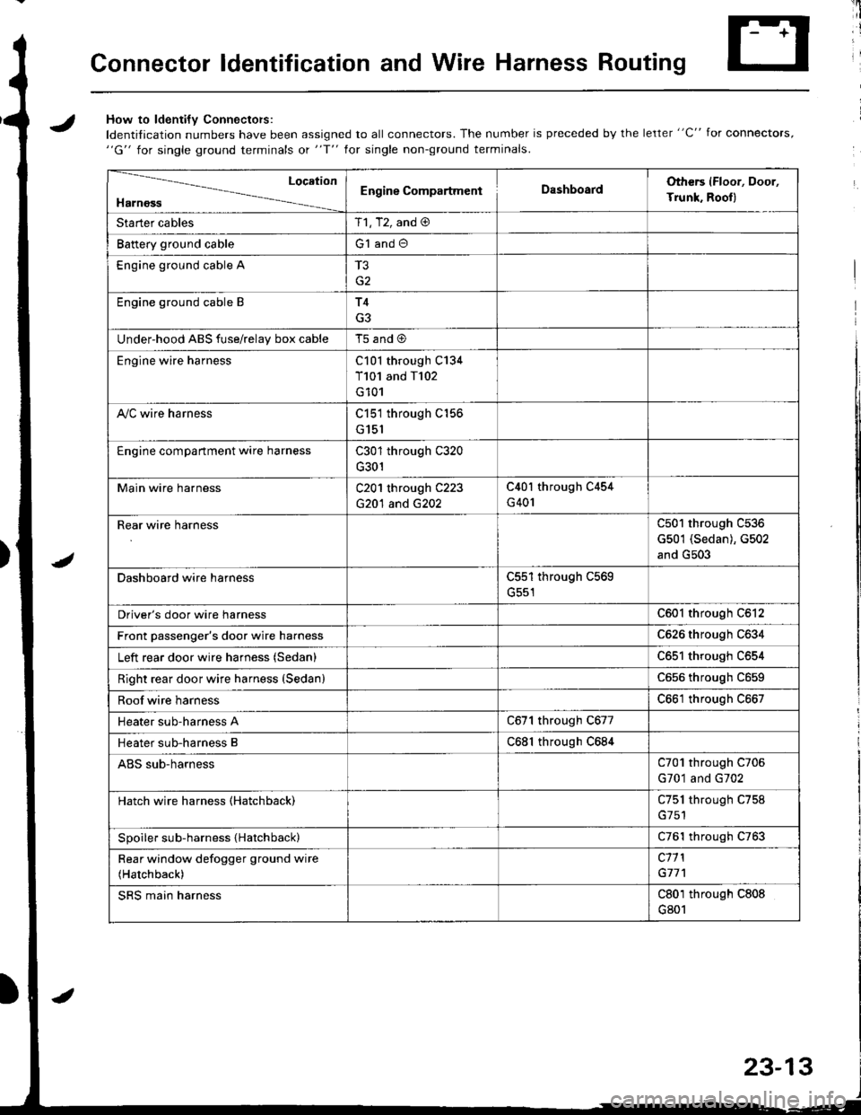
JHow to ldenti{v Connectors:
ldentification numbers have been assigned to all connectors. The number is preceded by the letter "C" for connectors,"G" for single ground terminals ot "f" lor single non-ground terminals.
/
Location
HarnossEngine CompartmentDashboardOthers (Floor, Door,
Trunk. Rooll
Starter cablesT1, T2, and @
Battery ground cableG1 and O
Engine ground cable A
G2
Engine ground cable BT4
G3
Under-hood ABS fuse/relav box cableT5 and @
Engine wire harnessC101 through C134
T101 and T102
G101
A,/C wire harnessC151 through C156
G151
Engine compartment wire harnessC301 through C320
G301
Main wire harnessC201 through C223
G20'l and G202
C40l through C454
G401
Rear wire harnessC501 through C536
G501 (Sedan), G502
and G503
Dashboard wire harnessC551 through C569
G551
Driver's door wire harnessC601 through C612
Front passenger's door wire harnessC626 through C634
Left rear door wire harness (Sedan)C65l through C654
Right rear door wire harness (SedanlC656 throughc659
Roof wire harnessC661 through C667
Heater sub-harness AC671 through C677
Heater sub-harness BC68l through C684
ABS sub-harnessC701 through C706
G701 and G702
Hatch wire harness (Hatchback)C751 through C758
Spoiler sub-harness {Hatchback)C761 through C763
Rear window defogger ground wire
(Hatchback)
c11 l
G77'l
SRS main harnessC801 through C808
G801
23-13
Page 1072 of 1680

Connector ldentification and Wire Harness Routing
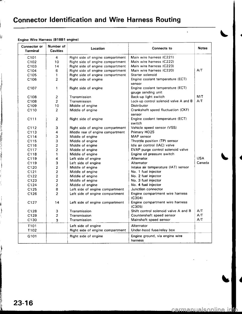
Connectot or
Terminal
Numbel of
CavitiesLocationConnects toNotes
c'to 1
c102
c103
c'1 04
c105
c106
c 107
c108
c108
c109
c110
c112
c113
c'r 14
c115
c116
c117
c118
ct'l9
c119
c120
c121
c122
c124
c't 26
c127
c128
c129
c130
c111
4
10
14
6
I
1
2
2
10
2
3
2
J
4
3
3
2
2
I
3
2
2
2
2
2
I
2
14
Right side of engine compartment
Right side of engine compartment
Right side ot engine compartment
Right side of engine compartment
Right side oI engine compartment
Right side of engine
Right side of engine
Transmission
Transmission
Middle ot engine
Middle ot engine
Right side of engine
Right side of engine compartment
Middle rear of engine compartment
N4iddle of engine
N4iddle ol engine
Middle oI engine
Nliddle ot engine
Middle of engine
Lelt side of engine
Left side of engine
Middle of engine
Middle oI engine
Middle of engine
Middle of engine
Middle ot engine
Left side of engine compartment
Lelt side ot engine compartment
Left side of engine compartment
Transmission
Transmission
Transmission
Main wire harness (C221)
Main wire harness (C222)
Main wire harness 1C223)
lvlain wire harness (C220)
Starter solenoid
Engine coolant temperature (ECT)
sensor
Engine coolant temperature (ECT)
gauge sending unit
Back-up light switch
Lock-up control solenoid valve A and B
Distributor
Crankshatt speed fluctuation (CKF)
sensor
Engine coolant temperature (ECT)
switch
Vehicle speed sensor (VSS)
Primary HO2S
MAP sensor
Throttle position (TP) sensor
ldle air control (lAC) valve
EVAP purge control solenoid valve
Engine oil pressure switch
Alternator
Alternator
lntake air temperature (lAT) sensor
No. 1 fuel injector
No. 2 fuel injector
No. 3 fuel injector
No. 4 fu€l injector
Junction connector
Engine compartment wire harness
(c304)
Engine compartment wire harness
(c30s)
Shift control solenoid valve A and B
Countershaft speed sensor
lvlainshaft speed sensor
M/T
NT
USA
Canada
Afi
Afi
T101
T102
Left side oI engine
Right side of engine compartment
Alternator
Under hood fuse/relay box
G'1 01Right side oI engineEngine ground. via engine wire
harness
Engine Wire Harness (B188l enginel
23-16
Page 1074 of 1680

Connector ldentification and Wire Harness Routing
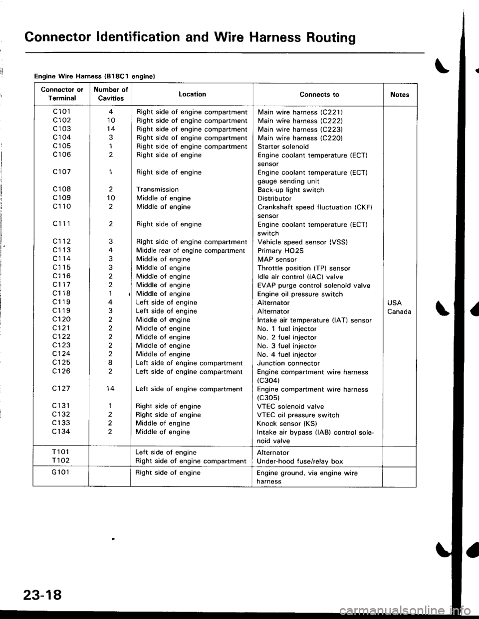
Engine Wire Harness (B18Cl enginel
Connectol ol
Terminal
Number of
CavitiesLocationConnects toNotes
c 101
c102
c103
c104
c105
c106
c101
c108
cr09
c110
c'r 11
cl12
c1't3
c114
c115
c116
cl17
c118
c119
c119
c120
cI2'l
cl24
c126
c127
cl31
c132
c133
c134
10
14
3
1
2
1
2
10
2
'I
3
2
2
2
I
1
2
2
?
3
2
14
Right side of engine compartment
Right side of engine compartment
Right side of engine compartment
Right side ol engine compartment
Right side of engine compartment
Righr side oI engine
Right side of engine
Transmission
Middle of engine
Middle of engine
Right side of engine
Right side of engine compartment
Middle rear of engine compartment
Middle of engine
Middle of engine
Middle of engine
Middle of engine
i/iddle of engine
Left side ot engine
Lelt side ot engine
Middle ot engine
Middle of engine
Middle of engine
Middle of engine
Middle of engine
Left side of engine companment
Left side of engine compartment
Lelt side of engine compartment
Right side of engine
Right side of engine
Middle of engine
Middle of engine
lvlain wire harness (C221 )
Main wire harness {C222)
Main wire harness (C223)
Main wire harness (C220)
Starter solenoid
Engine coolant temperature (ECT)
sensor
Engine coolant temperature (ECT)
gauge sending unit
Back-up light switch
Distributor
Crankshalt speed fluctuation (CKFI
sensor
Engine coolant temperature {ECT)
switch
Vehicle speed sensor (VSS)
Primary HO2S
MAP sensor
Throttle position {TP) sensor
ldle air control (lAC) valve
EVAP purge control solenoid valve
Engine oil pressure switch
Alternator
Alternator
Intake air temperature llAT) sensor
No. 1 fuel injector
No. 2 fuel injector
No. 3 tuel injector
No. 4 tuel injector
Junctron connector
Engine compartment wire harness(c304)
Engine companment wire harness(c30s)
VTEC solenoid valve
VTEC oil pressure switch
Knock sensor (KS)
Intake air bypass {lAB) control sole-
noid valve
USA
Canada
T101
r 102
Left side ot engine
Right side of engine compartment
Alternator
Under-hood fuse/relay box
G 101Right side of engineEngine ground, via engine wire
naaness
23-18
Page 1076 of 1680

Connector ldentification and Wire Harness Routing
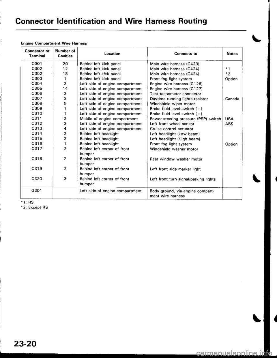
Engine Compartment Wire Halness
nll
Connectoa ot
Terminal
Number of
CavitiesLocationConnects toNotes
c301
c302
c 302
c303
c304
c306
c307
c308
c309
c310
c3l 1
c312
c314
c316
c317
c318
c319
c320
20
't8
1
14
2
3
5
1
1
2
2
4
2
2
1
2
2
2
3
Behind left kick panel
Behind left kick panel
Behind left kick panel
Behind left kick panel
Lett side of engine compartment
Lett side of engine companment
Lett side of engine compartment
Left side of engine compartment
Left side of engine compartment
Left side of engine compartment
Left side of engine compartment
Middle of engine compartment
Lett side of engine companment
Left side of engine compartment
Behind left headlight
Behind left headlight
Behind left headlight
Behind left corner of front
DUmper
Behind left corner ol front
bumper
Behind lett corner of front
bumper
Behind left co.ner of lront
bumper
Main wire harness (C423)
Main wire harness {C424)
N4ain wire harness (C424)
Front fog light system
Engine wire harness (C126)
Engine wire harness (C'127)
Test tachometer connector
Daytime running lights resistor
Windshield wiper motor
Brake f luid level switch (+ )
Brake f luid level switch ( - )
Power steering pressure (PSP) switch
Lett front wheel sensor
Cruise control actuator
LeIt headlight (Low beam)
Lett headlight {High beam)
Front fog light system
Windshield washer motor
Rear window washer motor
Left front side marker light
Left front turn signal/parking lights
Option
Canada
USA
ABS
Option
G301Lelt side of engine compartmentBody ground, via engine compart-
ment wire harness
23-20