Page 965 of 1680
Trunk Lid
NOTE:
a An assistant is helpful when removing the trunk lid.
a Take care not to damage the t.unk lid and body.
a Open the trunk lid.
1. Disconnect the connectors and trunk lid opener ca'
ble. Remove the wire harness and trunk lid opner ca-
ble from the trunk lid.
NOTE: Before pulling out the wire harness, tie a
strang to the end ot it so you can pull it back in when
the trunk lid is reinstalled.
2. Remove the bolts, then remove the trunk lid.
> : Bolt locaiions, 4
6x LOmm
6!--'.'.'''* 9.8 N.m n.o ksf .m. l\
> : Clip locations
A> : Clip, 3B< : Clip, 1
4*i
wj?,/
CA : Clip, 5
&qr/
TRUNK LIDOPENER CAELE
TRUNK LIDLATCH(see page 20-1591
WIRE HARNESS3.lf necessary, remove the trunk lid hinge.
NOTE:
a Remove the rear shelt {see page 20-95).
CONNECTORCONNECTOR
a Remove the torsion bars with the torsion bar as-
sembly tool.
TRUNK LIDHINGE
TRUNK LIDOPENERCABLE
A
TRUNK LID
TORSION
(cont'd )
TRUNK LID
Replacement
20-151
Page 966 of 1680
Trunk Lid
Replacement (cont'dl
i
I
a Remove the bolts, then remove the trunk
nrnge.
V: Bolt locations, 4
tid
6x 1.0 mm9.8 N m {'1.0 kgt m,7.2 lbr'ftl
)
NOTE: Take care notto hit the rear wrndowwhen removing the bolts.
4. Installation is the reverse o{ the removal procedure.
NOTE:
a Make sure the connectors are connected properly.
a Adjust the torsion bars lore or aft with the tor
sion bar assembly tool as shown.
O =Normal PositionO = Higher tension
a Make sure the trunk lid locks securely.a Make sure the trunk lid opens properlv.a Adiust the trunk lid alignment.
Page 967 of 1680
NOTE: Before adjusting the trunk lid. loosen each bolt slightly.
1. Adjust the trunk lid hinges right and left, as well as fore and att, by using the elongated holes.
2. Turn the trunk lid edge cushions, as necessary. to make the trunk lid fit flush with the body at the rear and side edges.
3. Adjust the lit between the trunk lid and the trunk lid opening by moving the striker.
TNUNK LID EDGECUSHION
TRUNK LIOHINGE
NOTE: Move the striker right or left until it's centered
in the trunk lid latch as shown.6 r 1.0 mm9.8 N m (1.O kgf .m,
7 .2 tbt.ltl
6 x '1.0 mm
STRIKER
STFIKER
4. After adjustment, tighten each bolt securely.
Adjustment
20-153
Page 969 of 1680
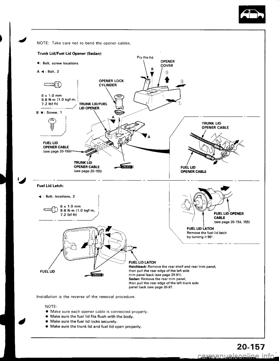
Trunk Lid/Fuel Lid Opener Cable (Sedan):
NOTE: Remove the rear seat (see page 20-1'l2l and center pillar lower trim (see page 20-94), then pull the carpet back, as
necessary {see page 20-126). Remove the left trunk side panel (see page 20-97).
C a: Clip, 1E A: Clip, 1D >: Clip, 3
w-l
)tQ,,
r-
> : Clip. cabl6 cushion locations
A >: Clip, 1 B V: Clip, 2
Qs , r>>.
lww-
F < | Cable cushion, 1
6t
ei
TRUNK LID LATCH(see page 20'159)
(see page 20,157)
Installation is the reverse of the removal procedure.
NOTE:
a Make sure each opener cable is routed and connected properly.
a Make sure the hood, hatch, trunk lid and fuel lid open properly.
OPENER(see page 20-157)
20-155
Page 971 of 1680

NOTE: Take care not to bend the opener cables.
Trunk Lid/Fuel Lid Opener lSedan):
<: Bolt, screw locations
A<:Bolt,2
OPENER LOCKCYLINDER
6 x 1.0 mm9.8 N m 11.o kgf m,
TRUNK LID/FUELLID
OPENER CABLE{see page 20-1
OPENERCOVER
z
tat-
7.2 tbt.trl /
B V: Screw, 1
rql.b.rz
rs? IY)
FUEL LID
TRUNK UDOPENER CABI.I(see page 20'155)
Pry the lid.
ta
Fuel Lid Latch:
: Bolt, locaiions, 2
6 x 1.O mm9.8 N.m 11.0 kgt m,7.2 tbl.trl J/)
FUEL LID OPEiIERCABLE(see page 20-154, 155)
FUEL LID LATCHRemove the fuel lid latchby turning it 90'.
FUEL LIO
Installation is the reverse of the removal procedure.
NOTEI
a Make sure each opener cable is connected properly.
a Make sure the fuel lid fits flush with the body.
a Make sure the tuel lid locks securely.
a Make sure the trunk lid and fuel lid open properly.
FUEL LID LATCHHatchbsck: Remove the rear shell and rear trim oanel,then pull the 196r edge of the left sidetrim panel back (see page 20-91).Sedan: Remove the rear trim panel,then pull the rear edge ol the left trunk sidepanel back (s€e page 20-97.
20-157
Page 972 of 1680
Hatch Latch and Lock Cylinder
Replacement
NOTE: Take care not to bend the cylinder rod and actua-
tor rod.
1. Remove the rear trim panel (see page 20-921.
2. Disconnect the cylinder rod and each connector.
CONNECTOR
3. Remove the bolts. then disconnect actuator rod.
Remove the hatch latch and actuator.
>: Screw loc6tion3
A>:3I >:3
ACTUATOR
20-158
4. Remove the lock cylinder by turning it 45".
>: Bolt location, 1
6x1.omm I9.8 N.m 11,0 kst m, il.ztb$ft| .)
lt: /
LOCKCYLINDEB
Installation is the reverse of the removal procedure.
NOTE:
a Apply grease to the hatch latch
a
a
a
Make sure the hatch locks securely.
Make sure the hatch opens properly.
N4ake sure the connector is connected properlV.
Page 974 of 1680
Retainers andWeatherstrip
Replacement
I
CAUTION: Wear glov3s to remove and install the retainers.
NOTE: Take care not to bend the retainers.
< : Screw locations, 19< : Clip locarions, 8
I "u+
\.-"
i4)
RETAINER
WEATHEBSTRIP
SHOP TOWEL
CEf{TER PILLARMOLDING
Roof side section:Center pillar section:
FRONT CENTER PILLAR
GLASS MOLDINGREAR
--l
I
FRONTGLASSCENTER PILLARMOLDING
NOTE: The numbers after the par1 namesshow the quantities ot the pans used.
WEATHER,STRIPPILLARWEATHER.STRIPRETAINER
Installation is the reverse of the removal procedure.
NOTE:
a Check the weatherstrip for damage or deterioration, and replace it it necessary.
a After installing the weatherstrip, check ,for water leaks.
a lJ necessary, adjust the position of the door glass (see page 2O-4O).
a ll necessary, replace any damaged clips.
REAR CLIP
RETAINER
WEATHERSTBIP
Page 979 of 1680

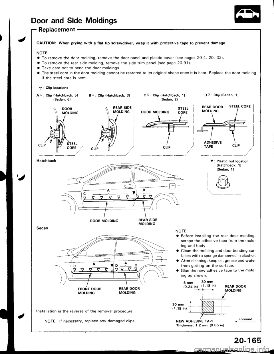
Door and Side Moldings
Replacement
JCAUTION: When prying with a tlat tip screwdriver, wrap it with protective tape to prevent damage.
NOTE:
a To remove the door molding, remove the door panel and plastic cover (see pages 20 4, 20, 32]'.
a To remove the rear side molding, remove the side trim panel (see page 20 91).
a Take care not to bend the door moldings.
a The steel core in the door molding cannot be restored to its original shape once it is bent. Replace the door molding
if the steel core is bent.
V I Clip locations
AV: Clip (Hatchback, 5) BV: Clip {Hatchback, 3)Dv: Clip lsedan, 1lCV : Clip {Harchback, 'l )(Sedan.2)
STEELOOOR MOLDING CORE
STEEL COBE
CORE
Hatchback
Sedan
V : Plastic nut location{Hatchback, 1llsedan, 1)
FRONT DOOBMOLDING
Installation is the reverse of the removal procedure.
NOTE: lf necessary, replace any damaged clips.NEW AOHESIVE TAPEThickness: 1.2 mm {0.05 in}
(Sedan,6)
A DOOR rvrororuc
lS
#'\---- -tl-t-f- i
ricLrP
/
REAR DOORMOLDING
O'
t
DOOR MOLDING
!@
NOTE:a Before installing the rear door molding,
scrape the adhesive tape from the mold
ing and body.
a Clean the molding and door bonding sur
faces with a sponge dampened in alcohol.
a A{ter cleaning, keep oil, grease and water
Irom getting on the surJace.
a Glue the new adhesive tape to the mold
ing as shown.
6mm 30mm
(0.24 in) {1.18 in}
20-165