Page 950 of 1680
Dashboard
Component Removal/lnstallation (cont'dl
Side air vent removal:
Driver's
1. Remove the dashboard lower cover (see page 20-
133).
2. Carefully pry the moonroof switch out of the side
air vent, then disconnect the conneclor.
Pry here.
3. Remove the screw, then remove the side air vent.
> : Screw locstion,
I
6F- i
------r/
< : Clip, hook locations
A<: Clip, 1
BV : Hook, 3
Installation is the reverse of the removal procedure.
NOTE: Make sure the connector is connected
properly.
20-136
Flont passenger's
Carefully pry the side air vent at the lower edge, then
pull it out.
A: Clip. hook locations
AA : Clip, 1BV: Hook, 2
SIDE AIRVENT
PROTECTIVETAPE
Side delogger trim removal:
Carefully pry the side defogger trim at the rear edge, then
remove it.
A : Clip, hook locations
AA: Clip,lB A: Hook, 1
_1_iF
/KHOOK cLtP /
Page 953 of 1680
Replacement
1. To remove the dashboard, tirst remove the:
a Front seats {see page 20-'103)
a Front and rear consoles (see page 20-130)
a Oashboard lower cover {see page 20-133)
a Knee bolster (see page 20-134)
. Glove box (see page 20-137). Clock (see page 20-1371
. Moonroof switch (see page 20-136)
a Stereo radio/cassette (see page 20-134)
2. Lower the steering column (see section 17).
NOTE: To prevent damage to the steering column,
wrap it with a shop towel.
l ; Boh, nut locations
AA : Bolr, 28
: Nut, 2
8 x 1.25 mm22 N.m 12.2 kgl.n,16 tbf.ft)o21 13 N m 11.3 kgl m,
\€J' Prbl rll
_Urr'rr,t __)
STEERING JOINTCOVER
STEERING COLUMN
3. Remove the nuts, then remove the front passenger's
airbag bracket.
: Nut locations, 4
6 x 1.0 mm L9.8Nm
{1.o kgt m,7.2tbt.rrUFRONT PASSENGEB'SAIRBAG
PASSENGER'S
SRS MAINAIRBAG BRACKET
HARNESS
4. Disconnect the air mix control cable and connectors.
AIR MIX CONTROLCABLE
HEATERCONTROLPANELCONNECTORS
(cont'd)
20-139
Page 957 of 1680

\
Bumpers
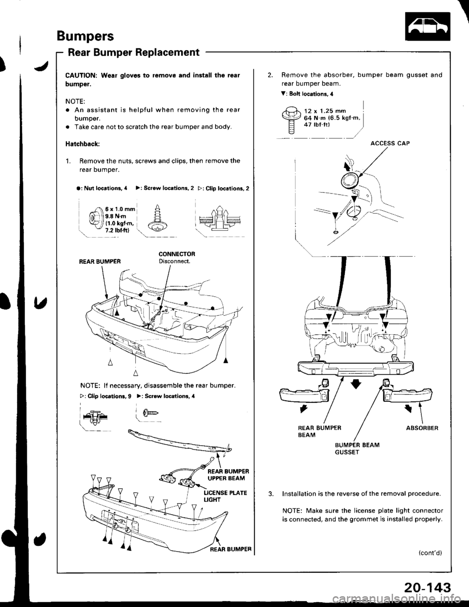
Rear Bumper Replacement
JCAUTION: Wear gloves to remove and install the rear
bumper.
NOTE:
. An assistant is helpful when removing the rear
bumper.
. Take care not to scratch the rear bumper and body.
Hatchback:
1. Remove the nuts, screws and clips, then remove the
rear bumper.
a: Nul locrtion3, a >: Scrow locations,2
n 6x1.0mm AffiJls.a N.- H
k i tr.o rgt.-, A. - 7.2 lbl.ftl t\+-z
\.!
>: Clip location3,2
REAR BUMPERCONNECTORDisconnect,
nQn
wl\lvxvn
\-:
NOTE: lf necessary, disassemble the rear bumper.
>: Clip locatiom, 9 >: Scr.w locationr. 4
l_4h- (E('-
\"
t s]@!-
BEAR BUMPERUPPER BEAM
LICENSE PLATELIGHT
REAR BUMPER
Remove the absorber, bumper
rear oumper Deam.
V: Boll locations,4
beam gusset and
12 x 1.25 mm64 N m 16.5 kgf m,47 rbf.rtl .)
ACCESS CAP
ABSOREER
BUMPER BEAMGUSSET
lnstallation is the reverse of the removal Drocedure.
NOTE: Make sure the license plate light connector
is connected, and the grommet is installed properly.
{cont'd)
,@
H
,lI
REAR BUMPER
20-143
Page 958 of 1680
Bumpers
REAR BUMPER
Rear Bumper Replacement (cont'd)
Sedan:
1. Remove the screw lrom each side.
Screw
A
,z::\+,1./
REAR BUMPER
2. Open the trunk lid, then remove the rear trim panel
(see page 20-97).
3. Disconnect the license plate light connector and
grommet from the rear trunk area. Remove the clips
and bolts, then remove the rear bumper.
V: Clip locations, 5 A: Bolt locations, 2
A
/.r-El^ El
=EE Atn) ('r\,
,/
*LICENSE PLATE LIGHTCONNECTOR
20-144
GROMMET
4. lf necessary, remove the license plate light harness,
bracket and lens from the rear bumper (see page
20-1431.
5. Remove the absorber, bumper beam gusset and rearoumper oeam.
V : Eolt locations, 4
12 x 1.25 mm I64 N.m 16.5 kgl.m, j
-::_:_)
fr)
Page 959 of 1680
Il
6. Installation is the reverse of the removal procedure.
NOTE;
r Make sure the license plate light connector is
connected, and the grommet is installed properly.
. Make sure the rear bumper engages the side clips
securely.
REAB BUMPER
20-145
Page 962 of 1680

Hatch
Replacement
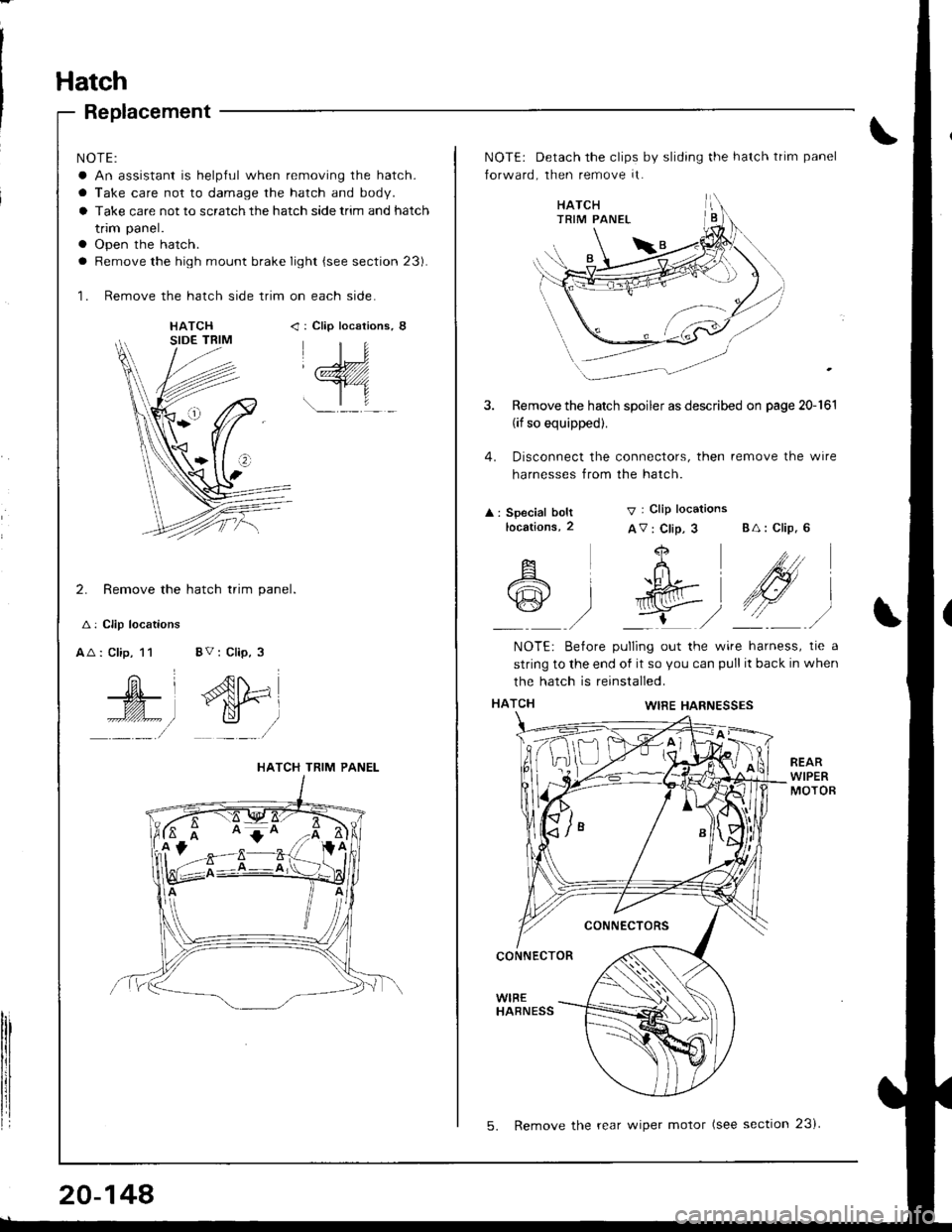
NOTE:
a An assistant is helpful when removing the hatch.
a Take care not to damage the hatch and body.
a Take care not to scratch the hatch side trim and hatch
trim panel.
a Open the hatch.
a Remove the high mount brake Iight {see section 23).
'1. Remove the hatch side trim on each side.
: Clip locaiions,
_);(zZZ////1
r.-lf
2. Remove the hatch trim panel
A: Clip locations
AA : Clip, 11 8V : Clip, 3
Ar^{N
# fN#=l*l y /
lrl
HATCH TRIM PANEL
20-148
5. Remove the rear wiper motor (see section 23i
NOTE: Detach the clips by sliding the hatch trim panel
forward, then remove it.
Remove the hatch spoiler as described on page 20-161
(if so equipped).
Disconnect the connectors, then remove the wire
harnesses from the hatch.
4.
A : Special boltlocations,2
V I Clip locations
AV: Clip, 3 BA: Clip. 6
i
I
A
A
w
+
..h [-
g)
bll
/\
NOTE: Betore pulling out the wire harness, tie a
string to the end of it so you can pull it back in when
the hatch is reinstalled.
WIRE HARNESSES
CONNECTORS
CONNECTOR
WIBEHABNESS
Page 963 of 1680

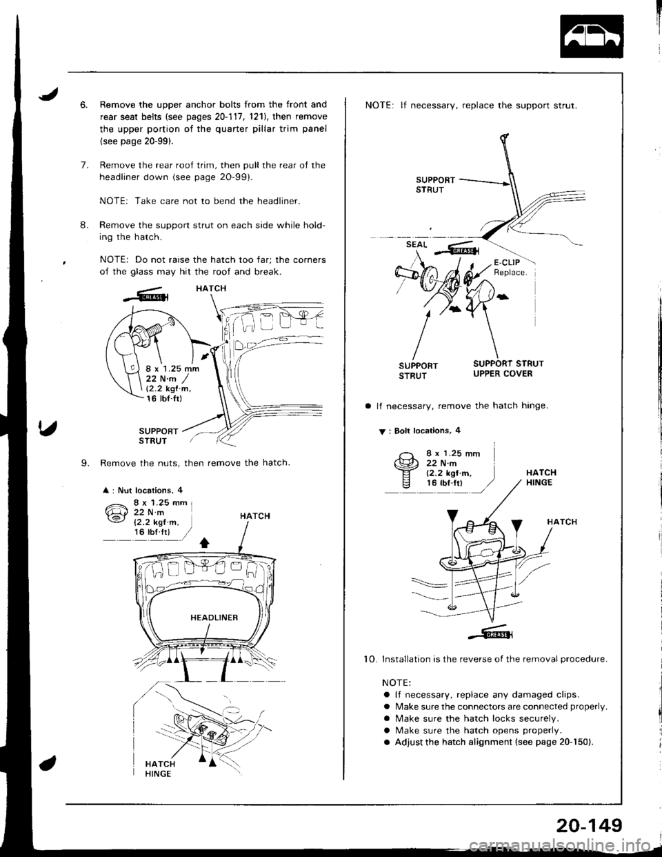
6.Remove the upper anchor bolts from the front and
rear seat belts (see pages 20-111,1211, then remove
the upper portion of the quarter pillar trim panel
(see page 20-99).
Remove the rear roof trim, then pull the rear of the
headliner down (see page 2O-99).
NOTE: Take care not to bend the headliner.
Remove the support strut on each side while hold-
ing the hatch.
NOTE: Do not raise the hatch too far; the corners
of the glass may hit the roof and break.
HATCH
8.
7.
SUPPORTSTRUT
L Remove the nuts, then remove the hatch.
: Nut locations, 4
22 N.m /12.2 kgl'm,16 tbt.fr)
HATCH
NOTE: lf necessary, replace the support strut.
lf necessary, remove the hatch hinge.
V : Boll locations, 4
I x 1.25 mm22 N.m(2.2 kgl.m,HATCH
10
HATCH
Installation is the reverse of the removal procedure.
NOTE:
a lf necessary, replace any damaged clips.
a Make sure the connectors are connected properly.
a N4ake sure the hatch locks securely.
a Make sure the hatch opens properly.
. Adjust the hatch alignment (see page 20-150).
20-149
Page 964 of 1680

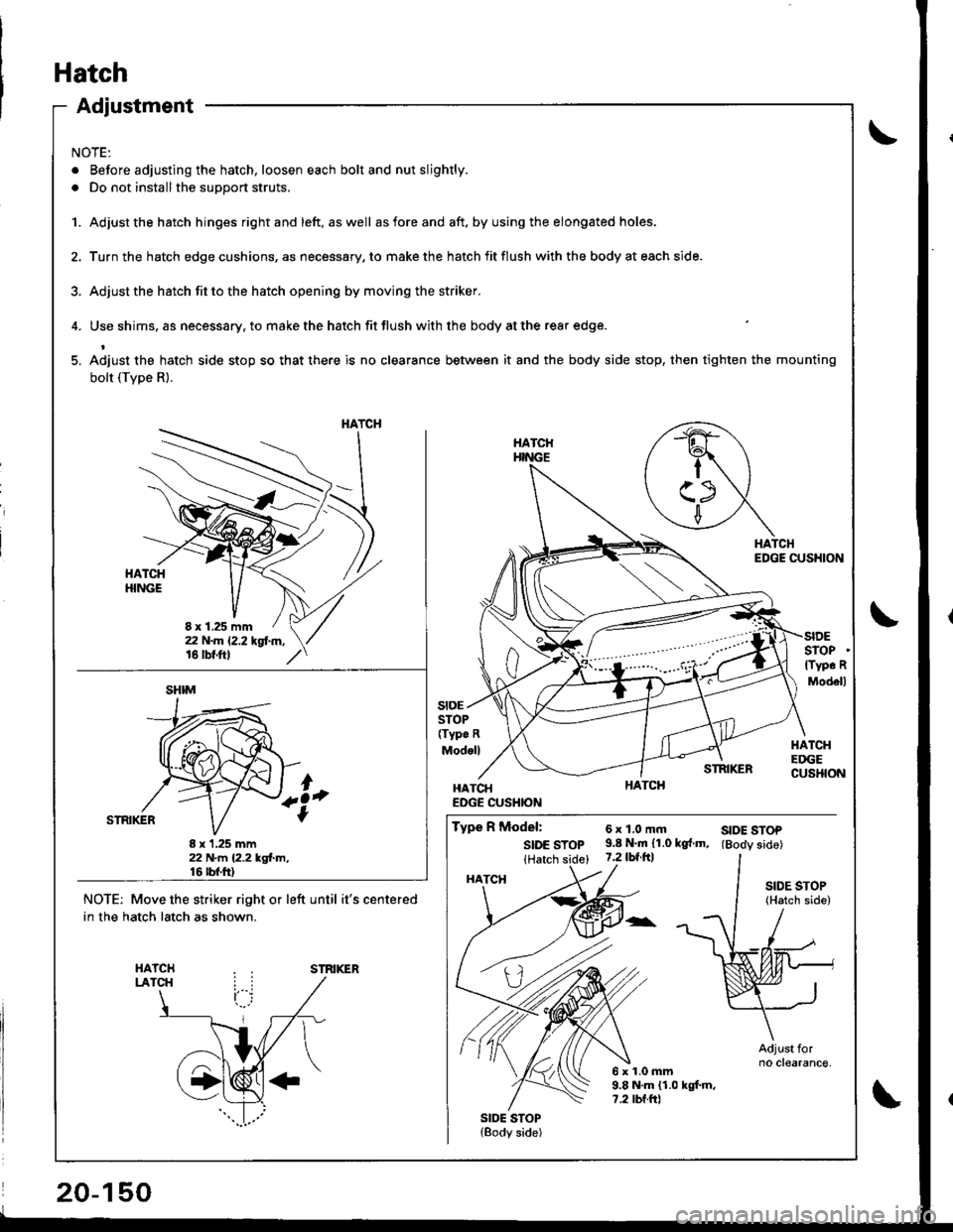
Adjustment
NOTE:
. Before adjusting the hatch, loosen each bolt and nut slightly.
. Do not installthe support struts.
1. Adjust the hatch hinges rightand left, aswell asforeand aft. byusing the elongated holes.
2. Turn the hatch edge cushions, as necessary, to make the hatch fit flush with the body at each side.
3. Adjust the hstch fit to the hatch opening by moving the striker.
4. Use shims. as necessary, to make the hatch fit flush with the body at the rear edge.
5. Adiust the hatch side stop so that there is no clearance between it and the body side stop, then tighten the mounting
bolt (Tvpe R).
HATCHEDGE CUSHION
STOP(Typ. R
Modoll
SIDESTOPlTyp. R
Modell
HATCHEDGECUSHION
stoE
STRIKER
HATCHEDGE CUSHION
Type R Model:
SIDE STOP(Hatch side)
SIDE STOP(Body side)
6xl,0mft9.8 N.m 11.0 kg{.m,7.2 tbf.ftl
6x1.0mm9.8 N.m (1.0 kgt m,?.2 tbf.ftl
SIDE STOP(Hatch side)
Adjust forno clearance,
SIDE STOP(Body side)
NOTE: Move the striker right or left until it's centered
in the hatch latch as shown.
STRIKER
HATCH
8 x 1.25 mm
SHIM
8 x 1.25 mm22 N.m 12.2 kgl.m,16 rbt.ft)
HATCH