Page 938 of 1680

Seat Belts
tor.
Hatchback
lnspection
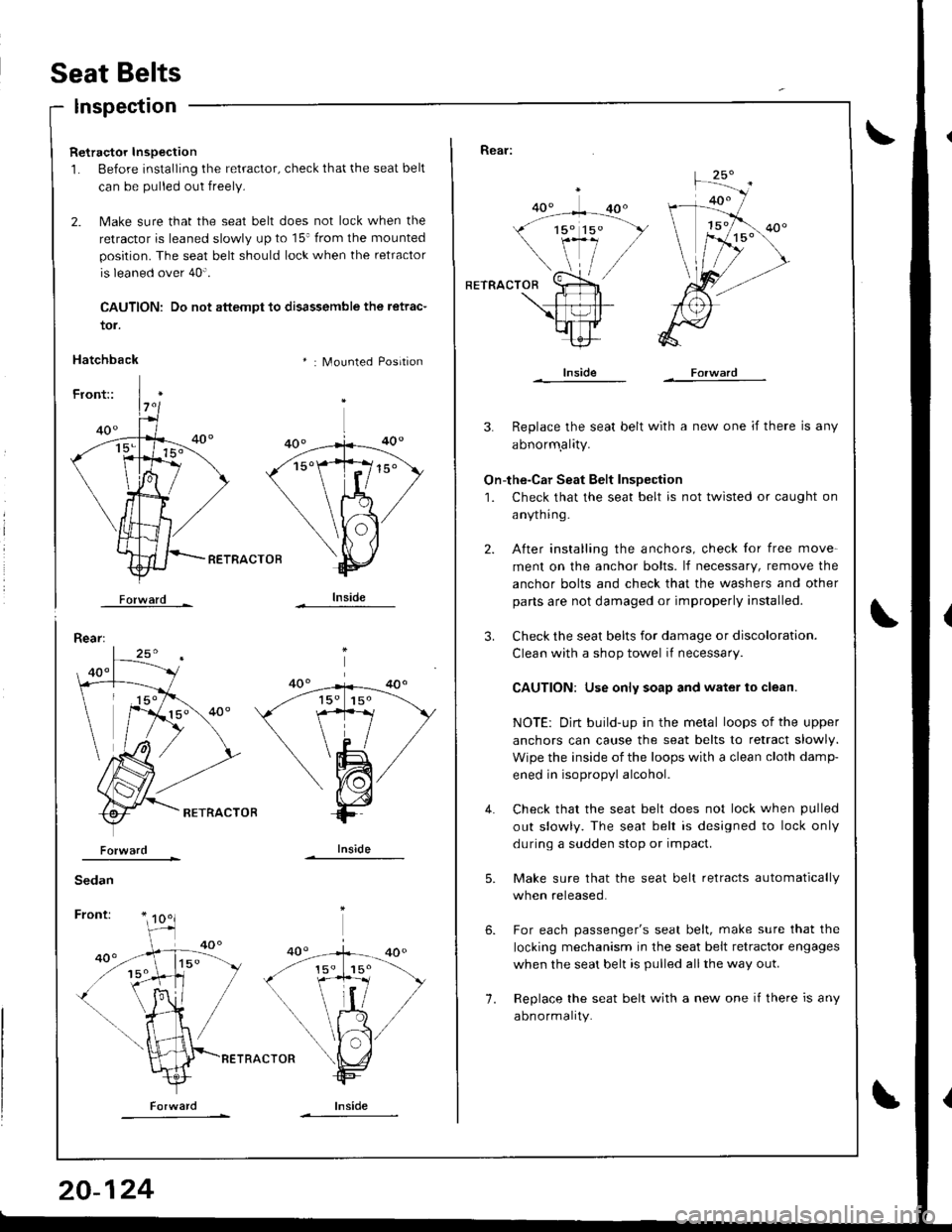
Retractor Inspection
1. Before installing the retractor, check that the seat belt
can be pulled out freely.
2. Make sure that the seat belt does not lock when the
retractor is leaned slowly up to 15' from the mounted
position. The seat belt should lock when the retractor
is leaned over 40".
CAUTION: Do not attempt to disassemble the retrac-
* : Mounted Position
RETRACTOB
Forward -
Rear:
lnside
Rear:
RETRACTOR
lnside
3. Replace the seat belt with a new one if there is any
abnorm.ality.
On-the-Car Seat Belt Inspection
1. Check that the seat belt is not twisted or caught on
anytnrng-
After installing the anchors, check for free move-
ment on the anchor bolts. lf necessary, remove the
anchor bolts and check that the washers and other
parts are not damaged or improperly installed.
Check the seat belts for damage or discoloration.
Clean with a shop towel if necessary
CAUTION: Use only soap and water to clean.
NOTE: Dirt build-up in the metal loops of the upper
anchors can cause the seat belts to retract slowly.
Wipe the inside of the loops with a clean cloth damp-
ened in isopropyl alcohol.
Check that the seat belt does not lock when pulled
out slowly. The seat belt is designed to lock only
during a sudden stop or impact.
Make sure that the seat belt retracts automatically
when released.
For each passenger's seat belt, make sure that the
locking mechanism in the seat belt retractor engages
when the seat belt is pulled allthe way out.
Replace the seat belt with a new one if there is any
abnormality.
4.
1.
6.
Page 939 of 1680

Child Seat Anchor Plate
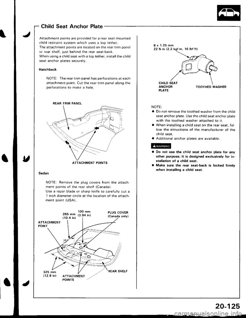
Attachment points are provided for a rear seat mounted
child restraint system which uses a top tether.
The attachment points are located on the rear trim panel
or rear shelf, just behind the rear seat-back.
When using a child seat with a top tether, installthe child
seat anchor plates securely.
Hatchback
NOTE: The rear trim panel has perlorations at each
attachment point. Cut the rear trim panel along the
perlorations to make a hole.
8 x 1.25 mm22 N.m 12.2.m, 16 lbf fr)
CHILD SEATANCHORPLATETOOTHED WASHER
NOTE:
a Do not remove the toothed washer from the child
seat anchor plate. Use the child seat anchor plate
with the toothed washer attached to it.
a When installlng a child seat on the rear seat, fol-
low the intructions ol the manufacturer of the
child seat.
a Additional anchor plates are available.
Do not use the child seat ancho. plate lor any
othel purpose; it is designed exclusively for in-
stallation ot a child seat.
Make sure the rear seat-back is locked tirmlv
when installing a child seat.Sedan
NOTE: Remove the plug covers trom the attach
ment points o{f the rear shelf {Canada).
Use a razor blade or sharp knife to carefully cut a
1 inch diameter circle at the location of the attach-
ment point {USA}.
265 mm110.4 in)
1OO mm(3.94 in)
R€AR TRIM PANEL
ATTACHMENT POINTS
REAR SHELF
Page 940 of 1680

Carpet
Beplacement
SRS wire harnesses are routed near the carpet.
CAUTION:
a All SRS wire harnesses are covered wilh yellow insu-
lation. Before you disconnect any palt of an SRS wire
harness, disconnect the airbag connectors.
a Whenever the ignition switch is ON (ll), or has been
tulned OFF fol less than three minutes, be caretul not
to bump the SRS unit; the airbags could accidentally
deploy and cause damage or inluries.
a Fof additional precautions, leter to the SRS sub-section
in section 23,
DRIVER'S AIRBAG FRONT
SRS UNIT
20-126
FOOTREST
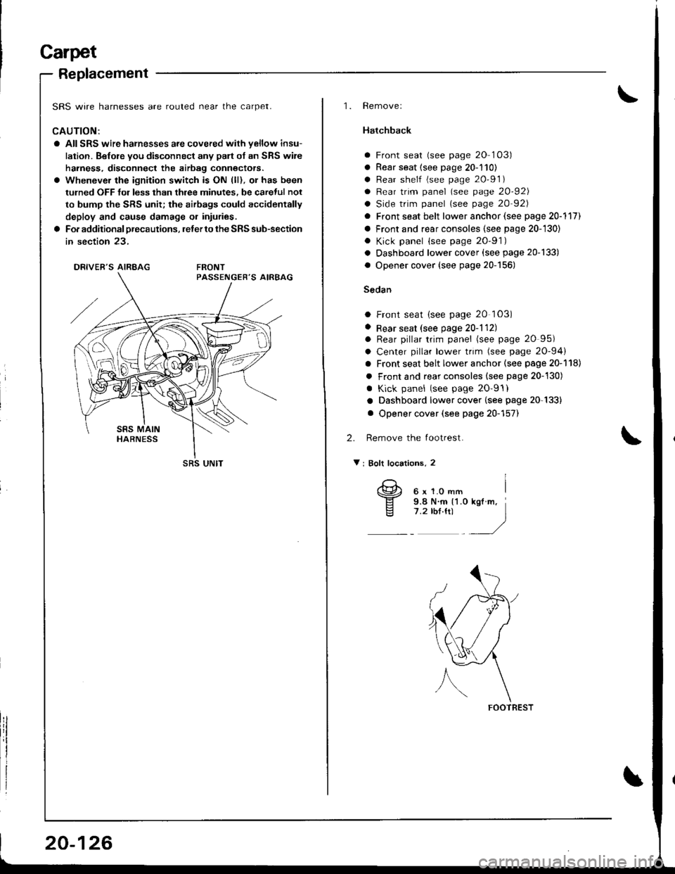
'1. Removel
Hatchback
a Front seat (see page 20 103)
a Rear seat (see page 20-110)
a Rear shelf (see page 20'91)
a Rear trim panel (see page 20-921
a Side trim panel (see page 20 92)
a Front seat belt lower anchor (see page 20-117)
a Front and rear consoles (see page 20-'130)
. Kick panel {see page 20-91)
a Dashboard lower cover (see page 20-133)
a Opener cover (see page 20-156)
Sedan
a Front seat (see page 20 103)
. Rear seat (see page 20-1121o Rear pillar trim panel (see page 20 95)
a Center pillar lower trim (see page 20-94)
a Front seat belt lower anchor (see page 20-118)
a Front and rear consoles (see psge 20-130)
. Kick panel (see page 20'9'l)
a Dashboard lower cover (see page 20-133)
a Opener cover (see page 20-157)
2. Remove the footrest.
V i Bolt locations, 2
6xl.omm i
9.8 N.m {'l .0 kgl m,7.2 rbf.ft) )./
Page 943 of 1680

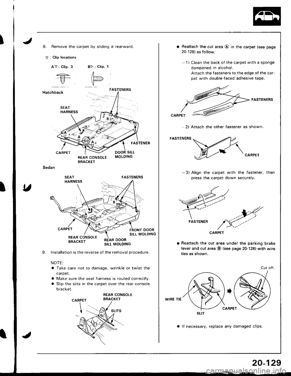
I8. Remove the carpet by sliding it rearward.
V : Clip locations
AV : Clip, 3BD : Clip. 1
A"= l
"
Hatchback
CARPET
Sedan
SEATHARNESS
FASTENERS
FASTENER
DOOR SILL
FASTENERS
oooRSILL MOLDING
SEATHARNESS
I
CARPET
REAR CONSOLEBRACKET
Installation is the reverse oJ the removal procedure.
NOTE:
a Take care not to damage, wrinkle or twist the
carpet.
a Make sure the seat harness is routed correctly.
a Slip the slits in the carpet over the rear console
bracket.
REAR CONSOLEBBACKETP
REAR DOORSILL MOLDING
9.
CAR
a Reattach the cut area @ in the carpet (see page
20-128) as follow.'
- 1) Clean the back of the carpet with a sponge
dampened in alcohol.
Attach the fasteners to the edge ol the car-
pet with double laced adhesive tape.
FASTENERS
CARPET
3) Align the carpet with the fastener,
press the carpet down securely.
then
CARPET
a Reattach the cut area under the parking brake
lever and cut area @ (see page 20-128) with wire
ties as shown.
WIRE TIE
Cut otl.
a lf necessary, replace any damaged clips.
2) Attach the other lastener as shown.
FASTENER
SLIT
20-129
Page 944 of 1680
Consoles, Front and Rear
Replacement
SRS wire harnesses are routed near the front console.
CAUTION:
a AIISRS wire harnesses are covered with vellow insu-
lation. Before you disconnect any pan of an SRS wire
halness, disconnect the airbag connectors.a Whenever the ignition switch is ON {lll, o. has beenturned OFF for less than three minutes, be carefulnot
to bump the SRS unit; the airbags could accidentally
deploy and cause damage or injuries.a For additional pfecautions, reter to the SRS sub-section
in section 23.
PASSENGER'S AIRBAG
SRS UNIT
20-130
NOTEr Take care not to scratch the lront and rear con-
soles, and dashboard.
1. Remove the access cap.
CAUTION: When prying with a tlat tip screwdriver.
wrap it with protective tape to prevent damage.
ACCESS CAP
2. Remove the screws.
V : Screw locations
AV : Screw, 2 BV : Screw, 2
el
Ei-,)
*)
Page 945 of 1680
3. Remove the rear console-
NOTE:
a Lift up the parking brake lever.
a Detach the hooks by lifting the front of the rear
console and sliding it rearward.
Remove the ashtray and front console panel.
> : Screw locations, 2
Disconnect the connector.
5. Remove the Screws.
NOTE: Remove the shift lever knob (M/T).
>; Screw locationi,4
!
6h:ro I",/
SHIFT LEVERKNOB
FRONT CONSOLE
6. Remove the front console as shown.
NOTE: Wrap the shift lever and Ay'T gear position indica-
tor panel with a shop towel to prevent damage.
20-131
Page 946 of 1680
Consoles, Front and Rear
Replacement (cont'dl
7. lf necessary, disassemble the front and rear con-soles.
>r Scrrw >: Clip locationsloc.tion3, 5 A >j Clip, 2 B >r Clip. 2 C >: Clip, 2
1F
\,,a';\\g.E/
20-132
: Screw locations, 9
A
Aw.)
REAR CONSOLE
PARKING BRAKECOVER
COVER SETPLATE
8. Installation is the reverse of the removal orocedure.
ARMREST
CONSOLE 80X
Page 948 of 1680

Dashboard
Component Removal/lnstallation (cont'dl
5. Remove the knee bolster.
: Bolt
A'ir
locations,3
6 x 1.0 mm9.8 N.m
{1.0 kgt m,7.2 tbf.fit
0
6. lnstallation is the reverse o{ the removal procedure.
Ste.eo ladio/cassette, Heatet contlol Danel removal:
1. Remove the rear console, then remove the front
console (see page 20-130).
Loosen the bolts, then remove the stereo radio/
cassette by pulling it out.
Disconnect the connector and antenna lead.
NOTEr The original radio has a coded theft protec-
tion circuit. Be sure to get the customer's code num-
ber before- disconnecting the battery.- removing the No. 47 (7.5 A) tuse from the under-
hood fuse/relay box.- removing the radio,
After service, reconnect power to the radio and turn
it on. When the word "CODE" is displayed, enter
the customer's 5-digit code to restore radio
ope.ation.
KNEE BOLSTER
20-134
CONNECTOR
CASSETTE
: Bolt locations, 2
6x1.0mm9.8 N.m {1.0 kgt m,
3. Carefully pry the hazard warning switch and rear
window detogger switch out of the heater control
panel.
Disconnect the connectors.
HAZARD WARNINGswtTcHREAR WINDOWDEFOGGER SWITCH
CONNECTORS