Page 612 of 1807
 HTS(+)
ECM
- DIAGNOSTICSENGINE (2JZ-GTE)
DI-197
425 Author�: Date�:
1997 SUPRA (RM502U)
DTC P0135 Heated Oxygen Sensor Heater Circuit
Malfunctio")
BE6653S02437A03033
ON
Check Harness A
B72, 71
HT1(+) HTS(+)
ECM
- DIAGNOSTICSENGINE (2JZ-GTE)
DI-197
425 Author�: Date�:
1997 SUPRA (RM502U)
DTC P0135 Heated Oxygen Sensor Heater Circuit
Malfunction (Bank 1 Sensor 1)
DTC P0141 Heated Oxygen Sensor Heater Circuit
Malfunction (Bank 1 Sensor 2)
CIRCUIT DESCRIPTION
Refer to ºInsufficient Coolant Temp. for Closed Loop Fuel Controlº on page DI-190.
DTC No.DTC Detecting ConditionTrouble Area
P0135
When the heater operates, heater current exceeds 2 A
(2 trip detection logic)�Open or short in heater circuit of heated oxygen sensor
Htd htP0135
P0141Heater current of 0.25 A or less when the heater operates
(2 trip detection logic)�Heated oxygen sensor heater
�ECM
HINT:
�Bank 1 refers to the bank that includes cylinder No.1.
�Sensor 1 refers to the sensor closer to the engine body.
�Sensor 2 refers to the sensor farther away from the engine body.
WIRING DIAGRAM
Refer to page DI-190 for the WIRING DIAGRAM.
INSPECTION PROCEDURE
1 Check voltage between terminals HT1, HTS of ECM connector and body ground.
PREPARATION:
(a) Connect Check Harness A (See page DI-164).
(b) Turn ignition switch ON.
CHECK:
Measure voltage between terminals HT1, HTS of ECM connec-
tor and body ground.
HINT:
�Connect terminal HT1 to bank 1 sensor 1.
�Connect terminal HTS to bank 1 sensor 2.
OK:
Voltage: 9 - 14 V
OK Check and replace ECM (See page IN-28).
NG
DI4SW-01
Page 618 of 1807
- DIAGNOSTICSENGINE (2JZ-GTE)
DI-203
431 Author�: Date�:
1997 SUPRA (RM502U)
5 Check mass air flow meter and engine coolant temp. sensor
(See page DI-170, DI-179).
NG Repair or replace.
OK
6 Check for spark and ignition (See page IG-1).
NG Repair or replace.
OK
Check and replace ECU (See page IN-28).
Page 619 of 1807

432 Author�: Date�:
1997 SUPRA (RM502U)
DTC P0300 Random/Multiple Cylinder Misfire Detected
DTC P0301 Cylinder 1 Misfire Detected
DTC P0302 Cylinder 2 Misfire D")
DI-204
- DIAGNOSTICSENGINE (2JZ-GTE)
432 Author�: Date�:
1997 SUPRA (RM502U)
DTC P0300 Random/Multiple Cylinder Misfire Detected
DTC P0301 Cylinder 1 Misfire Detected
DTC P0302 Cylinder 2 Misfire Detected
DTC P0303 Cylinder 3 Misfire Detected
DTC P0304 Cylinder 4 Misfire Detected
DTC P0305 Cylinder 5 Misfire Detected
DTC P0306 Cylinder 6 Misfire Detected
CIRCUIT DESCRIPTION
Misfire: The ECM uses the crankshaft position sensor and camshaft position sensor to monitor changes in
the crankshaft rotation for each cylinder.
The ECM counts the number of times the engine speed change rate indicates that misfire has occurred.
When the misfire rate equals or exceeds the count indicating that the engine condition has deteriorated, the
MIL lights up.
If the misfire rate is high enough and the driving conditions will cause catalyst overheating, the MIL blinks
when misfiring occurs.
DTC No.DTC Detecting ConditionTrouble Area
P0300Misfiring of random cylinders is detected during the any
particular 200 or 1,000 revolutions�Ignition system
�Injector
P0301
P0302
P0303For any particular 200 revolutions of the engine, misfiring is
detected which can cause catalyst overheating (This causes
MIL to blink)
j
�Fuel line pressure
�EGR
�Compression pressure
�
Valve clearance not to specificationP0303
P0304
P0305
P0306For any particular 1,000 revolutions of the engine, misfiring
is detected which causes a deterioration in emission (2 trip
detection logic)
�Valve clearance not to specification
�Valve timing
�Mass air flow meter
�Engine coolant temp. sensor
HINT:
When the 2 or more codes for a misfiring cylinder are recorded repeatedly but no Random Misfire code is
recorded, it indicates that the misfires were detected and recorded at different times.
DI4SZ-01
Page 620 of 1807
FI6934
Battery
B
2A
1
AM2
R/B No.2 2 W-R
IB1 4Ignition Switch
B-W
76IJ19
B-O
1 Solenoid Resistor
2
3
4
8
7
62
2
2
2
2
21
1
1
1
1
1 Injector
No.1
No.2
No.3
No.4
No.5
No.6R-L
R-Y
R-G
R-W
R
R-B
BR
BR
ED
B
B
B
B
B
B
B
B 20
19
18
17
16
15
80
79#10
#20
#30
#40
#50
#60
E01
E02
ECM
W-R
W B-YGR BRL
FI6588
FI6538
A00064
100 m sec./Division (Idling)
1 m sec./Division (Idling)
Injection Duration 10 V/
Division(Magnification)
GND GND 10 V/
Division
- DIAGNOSTICSENGINE (2JZ-GTE)
DI-205
433 Author�: Date�:
1997 SUPRA (RM502U)
WIRING DIAGRAM
Reference INSPECTION USING OSCILLOSCOPE
INJECTOR SIGNAL WAVEFORM
With the engine idling, measure between terminals #10 - #60 and E01 of ECM.
HINT:
The correct waveform is as shown.
Page 621 of 1807
P11799 IG0317 IG0151
A03065
1.1 mm
DI-206
- DIAGNOSTICSENGINE (2JZ-GTE)
434 Author�: Date�:
1997 SUPRA (RM502U)
INSPECTION PROCEDURE
1 Check spark plug and spark of misfiring cylinder.
PREPARATION:
(a) Remove the ignition coil (See page IG-6).
(b) Remove the spark plug.
CHECK:
(a) Check the carbon deposits on electrode.
(b) Check electrode gap.
OK:
(1) No large carbon deposit present.
Not wet with gasoline or oil.
(2) Electrode gap: 1.1 - 1.3 mm
(0.043 - 0.051 in.)
PREPARATION:
(a) Install the spark plug to the ignition coil, and connect the
ignition coil connector.
(b) Ground the spark plug.
(c) Disconnect injector connector.
CHECK:
Check if spark occurs while the engine is being cranked.
NOTICE:
To prevent excess fuel being injected from the injectors
during this test, don't crank the engine for more than 5 - 10
sec. at a time.
OK:
Spark jumps across electrode gap.
NG Replace or check ignition system (See page
IG-1).
OK
Page 622 of 1807
A00700
ON
Check Harness A
ECM
B20, 19, 18, 17, 16, 15
#10
(+)#20
(+)#30
(+)#40
(+)#50
(+)#60
(+)
- DIAGNOSTICSENGINE (2JZ-GTE)
DI-207
435 Author�: Date�:
1997 SUPRA (RM502U)
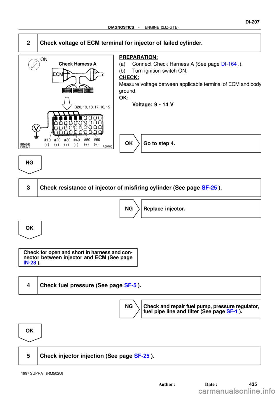
2 Check voltage of ECM terminal for injector of failed cylinder.
PREPARATION:
(a) Connect Check Harness A (See page DI-164.).
(b) Turn ignition switch ON.
CHECK:
Measure voltage between applicable terminal of ECM and body
ground.
OK:
Voltage: 9 - 14 V
OK Go to step 4.
NG
3 Check resistance of injector of misfiring cylinder (See page SF-25).
NG Replace injector.
OK
Check for open and short in harness and con-
nector between injector and ECM (See page
IN-28).
4 Check fuel pressure (See page SF-5).
NG Check and repair fuel pump, pressure regulator,
fuel pipe line and filter (See page SF-1).
OK
5 Check injector injection (See page SF-25).
Page 624 of 1807

1W
Knock Sensor 2
(On rear side)
1WB
B 50
49
KNK2 KNK1ECM
E1
- DIAGNOSTICSENGINE (2JZ-GTE)
DI-209
437 Author�: Date�:
1997 SUPRA (RM502U)
DTC P0325 Knock Sensor")
P22425
Knock Sensor 1
(On front side)
1W
Knock Sensor 2
(On rear side)
1WB
B 50
49
KNK2 KNK1ECM
E1
- DIAGNOSTICSENGINE (2JZ-GTE)
DI-209
437 Author�: Date�:
1997 SUPRA (RM502U)
DTC P0325 Knock Sensor 1 Circuit Malfunction
DTC P0330 Knock Sensor 2 Circuit Malfunction
CIRCUIT DESCRIPTION
Knock sensors are fitted one each to the front and rear of the left side of the cylinder block to detect engine
knocking. This sensor contains a piezoelectric element which generates a voltage when it becomes de-
formed, which occurs when the cylinder block vibrates due to knocking. If engine knocking occurs, ignition
timing is retarded to suppress it.
DTC No.DTC Detecting ConditionTrouble Area
P0325No knock sensor 1 signal to ECM with engine speed between
2,050 rpm and 5,950 rpm�Open or short in knock sensor 1 circuit
�Knock sensor 1 (looseness)
�ECM
P0330No knock sensor 2 signal to ECM with engine speed between
2,050 rpm and 5,950 rpm�Open or short in knock sensor 2 circuit
�Knock sensor 2 (looseness)
�ECM
If the ECM detects the above diagnosis conditions, it operates the fail safe function in which the corrective
retard angle value is set to the maximum value.
WIRING DIAGRAM
DI4T0-01
Page 631 of 1807

Idling
IG SW OFF
Warm up
3 - 5 min.
2 min.3 - 5 min.
2 min.Time
(7) (6)
(5) (7) (3)
(2) (1) DI-218
- DIAGNOSTICSENGINE (2JZ-GTE)
446 Author�: Date�:
1997 SUPRA (RM5")
P20769
70 - 90 km/h
(43 - 56 mph)
Idling
IG SW OFF
Warm up
3 - 5 min.
2 min.3 - 5 min.
2 min.Time
(7) (6)
(5) (7) (3)
(2) (1) DI-218
- DIAGNOSTICSENGINE (2JZ-GTE)
446 Author�: Date�:
1997 SUPRA (RM502U)
SYSTEM CHECK DRIVING PATTERN
(1) Connect the OBDII scan tool or TOYOTA hand-held tester to the DLC3.
(2) Start the engine and warm it up with all accessories switched OFF.
(3) Run the vehicle at 70 - 90 km/h (43 - 56 mph) for 3 min. or more.
(4) Idle the engine for about 2 min.
(5) Stop at safe place and turn the ignition switch OFF.
(6) Start the engine and do steps (3) and (4) again.
(7) Check the ºREADINESS TESTSº mode on the OBDII scan tool or TOYOTA hand-held tester. If ºCOMPLº
is displayed and the MIL does not light up, the system is normal. If ºINCMPLº is displayed and the MIL does
not light up, run the vehicle again and check it.
HINT:
ºINCMPLº is displayed when either condition (a) or (b) exists.
�The system check is incomplete.
�There is a malfunction in the system.
If there is a malfunction in the system, the MIL will light up after steps (2) to (6) above are done.