Page 963 of 1807
 Cruise control does not cancel when clutch pedal depressed.
Input signal check No.3: OK
1. Cruise Control ECU
Input")
DI-672
- DIAGNOSTICSCRUISE CONTROL SYSTEM
900 Author�: Date�:
1997 SUPRA (RM502U) Cruise control does not cancel when clutch pedal depressed.
Input signal check No.3: OK
1. Cruise Control ECU
Input signal check No.3: NG
1. Clutch Switch Circuit
2. Cruise Control ECU
IN-28
DI-697
IN-28
Cruise control does not cancel when cruise control switch turned
to CANCEL.
Input signal check No.3: OK
1. Cruise Control ECU
Input signal check No.3: NG
1. Control Switch Circuit
2. Cruise Control ECU
IN-28
DI-682
IN-28
Vehicle speed does not decrease when cruise control switch
turned to COAST.
Input signal check No.1: OK
1. Actuator Motor Circuit
2. Actuator Control Cable
3. Vehicle Speed Sensor Circuit
4. Cruise Control ECU
Input signal check No.1: NG
1. Control Switch Circuit
2. Cruise Control ECU
DI-673
DI-710
DI-679
IIN-28
DI-682
IN-28
Vehicle speed does not accelerate when cruise control switch
turned to ACCEL.
Input signal check No.2: OK
1. Actuator Motor Circuit
2. Actuator Control Cable
3. Vehicle Speed Sensor Circuit
4. Cruise Control ECU
Input signal check No.2: NG
1. Control Switch Circuit
2. Cruise Control ECU
DI-673
DI-710
DI-679
IIN-28
DI-682
IN-28
Vehicle speed does not return to memorized speed when cruise
control switch turned to RESUME.
Input signal check No.2: OK
1. Actuator Motor Circuit
2. Actuator Control Cable
3. Vehicle Speed Sensor Circuit
4. Cruise Control ECU
Input signal check No.2: NG
1. Control Switch Circuit
2. Cruise Control ECU
DI-673
DI-710
DI-679
IN-28
DI-682
IN-28
Speed can be set below about 40 km/h (25 mph).
Input signal check No.4: OK
1. Cruise Control ECU
Input signal check No.4: NG
1. Vehicle Speed Sensor Circuit
2. Cruise Control ECU
IN-28
DI-679
IN-28
Cruise control does not cancel when speed is less than 40 km/h
(25 mph).
Input signal check No.4: OK
1. Actuator Motor Circuit
2. Cruise Control ECU
Input signal check No.4: NG
1. Vehicle Speed Sensor Circuit
2. Cruise Control ECU
DI-673
IIN-28
DI-679
IIN-28
Page 966 of 1807

I02715
Cruise Control Actuator
Magnetic ClutchGND4
C4
C43
LBR-Y
R-L17
IB6
8
IB6W-B
R-L
Battery
STOP10
1I
J/B No.1WCruise Control ECU
13
43
21 S11
S11S11
S11
Stop Light SwitchB-W
G-W G-WC16
C16
C1610
16
To Light Failure SensorGND
L
STP-
- DIAGNOSTICSCRUISE CONTROL SYSTEM
DI-675
903 Author�: Date�:
1997 SUPRA (RM502U)
DTC 12 Magnetic Clutch Circuit
CIRCUIT DESCRIPTION
This circuit turns on the magnetic clutch inside the actuator during cruise control operation according to the
signal from the ECU. If a malfunction occurs in the actuator or speed sensor, etc. during cruise control opera-
tion, the rotor shaft between the motor and control plate is released.
When the brake pedal is depressed, the stoplight switch turns on, supplying electrical power to the stoplight.
Power supply to the magnetic clutch is mechanically cut and the magnetic clutch is turned OFF.
When driving downhill, if the vehicle speed exceeds the set speed by 15 km/h (6 mph) above the set speed,
then cruise control at the set speed is resumed.
DTC No.Detection ItemTrouble Area
12Short in magnetic clutch circuit
Open (0.8 sec.) in magnetic clutch circuit
�Cruise contorl actuator magnetic clutch
�Harness or connector between ECU and magnetic clutch,
magnetic clutch and body ground
�Cruise control ECU
WIRING DIAGRAM
DI4XR-01
Page 978 of 1807

N19613
22
1 2
4
3
10 16Cruise Control ECU
1B
I1 S11
S11G-W
B-W
Cruise Control Actuator R/B No.2
Battery
B 2A2
ALT
W-LJ/B No.1
STOP10
C16
L STP-
2 W-L
S11 S11
C16
POWERR-LR-LWStop Light Switch
- DIAGNOSTICSCRUISE CONTROL SYSTEM
DI-687
915 Author�: Date�:
1997 SUPRA (RM502U)
Stop Light Switch Circuit
CIRCUIT DESCRIPTION
When the brake is on, battery positive voltage normally applies through the STOP fuse and stop light switch
to terminal STP- of the ECU, and the ECU turns the cruise control off.
A fail-safe function is provided so that cancel functions normally, even if there is a malfunction in the stop
light signal circuit.
If the harness connected to terminal STP- has an open circuit, terminal STP- will have battery positive volt-
age and the cruise control will be turned off.
Also, when the brake is on, the magnetic clutch is cut mechanically by the stop light switch, turning the cruise
control off. (See page DI-675 for operation of the magnetic clutch)
WIRING DIAGRAM
DI4XX-01
Page 985 of 1807
I02725
Ignition Switch5
1JGAUGE
12
1E12
1H J/B No.1
Y
(M/T)1
C15
C152 Cruise Control Clutch Start Switch (M/T)
(M/T)G-R
G-R(A/T)
7IJ2 Y
23
II1
Y
(A/T)4
P2 P29 Park/Neutral Position Switch (A/T)
G-R2
C16
DCruise Control ECU
Y
*1: 2JZ-GTE Engine
*2: 2JZ-GE Engine
DI-694
- DIAGNOSTICSCRUISE CONTROL SYSTEM
922 Author�: Date�:
1997 SUPRA (RM502U)
Park/Neutral Position Switch Circuit
CIRCUIT DESCRIPTION
When the shift position is put in except D position, a signal is sent from the park/neutral position switch to
the ECU. When this signal is input during cruise control driving, the ECU cancels the cruise control.
WIRING DIAGRAM
INSPECTION PROCEDURE
1 Check starter operation.
CHECK:
Check that the starter operates normally and that the engine starts.
NG Proceed to engine troubleshooting
(2JZ-GE: See page DI-24,
2JZ-GTE: See page DI-169).
OK
DI4XZ-01
Page 988 of 1807

LightON
OFFSW ON
SW OFF
- DIAGNOSTICSCRUISE CONTROL SYSTEM
DI-697
925 Author�: Date�:
1997 SUPRA (RM502U)
Clut")
Input Signal
Indicator Light
Blinking Pattern
Clutch switch
OFF (Depress
clutch pedal)
LightON
OFFSW ON
SW OFF
- DIAGNOSTICSCRUISE CONTROL SYSTEM
DI-697
925 Author�: Date�:
1997 SUPRA (RM502U)
Clutch Switch Circuit
CIRCUIT DESCRIPTION
When the clutch pedal is depressed, the clutch switch sends a signal to the cruise control ECU. When the
signal is input to the cruise control ECU during cruise control driving, the cruise control ECU cancels cruise
control.
WIRING DIAGRAM
Refer to park/neutral position switch circuit on page DI-694.
INSPECTION PROCEDURE
1 Check starter operation.
CHECK:
Check that the starter operates normally and that the engine starts.
NG Proceed to engine troubleshooting
(2JZ-GE: See page DI-24,
2JZ-GTE: See page DI-169).
OK
2 Input signal check.
PREPARATION:
See input signal check on page DI-662.
CHECK:
Check the indicator light when the clutch pedal is depressed.
OK:
The indicator light goes off when the clutch pedal is
depressed.
OK Proceed to next circuit inspection shown on
problem symptoms table (See page DI-671).
NG
DI4Y0-01
Page 989 of 1807
I02726
ON
(-)
D (+)
DI-698
- DIAGNOSTICSCRUISE CONTROL SYSTEM
926 Author�: Date�:
1997 SUPRA (RM502U)
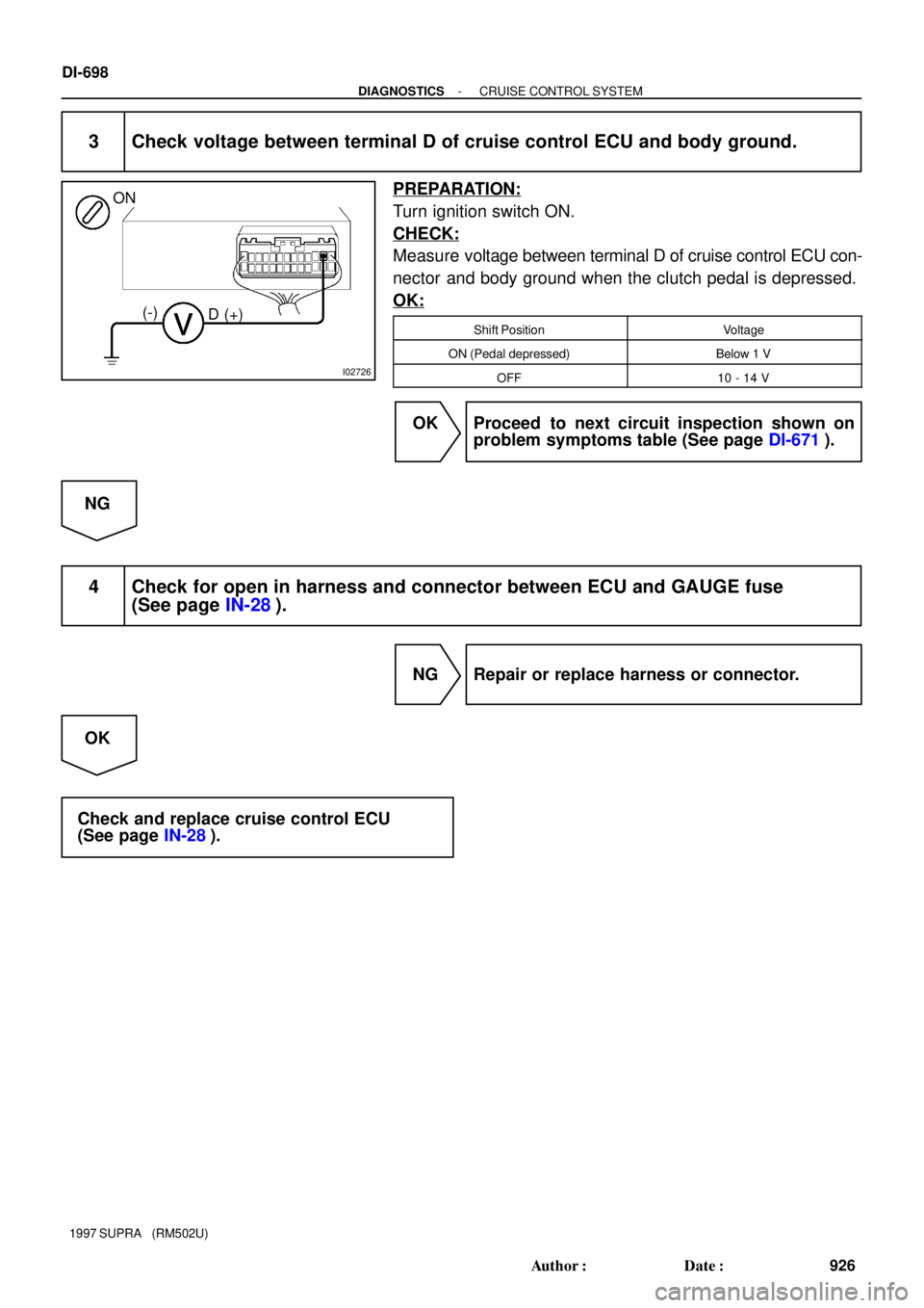
3 Check voltage between terminal D of cruise control ECU and body ground.
PREPARATION:
Turn ignition switch ON.
CHECK:
Measure voltage between terminal D of cruise control ECU con-
nector and body ground when the clutch pedal is depressed.
OK:
Shift PositionVoltage
ON (Pedal depressed)Below 1 V
OFF10 - 14 V
OK Proceed to next circuit inspection shown on
problem symptoms table (See page DI-671).
NG
4 Check for open in harness and connector between ECU and GAUGE fuse
(See page IN-28).
NG Repair or replace harness or connector.
OK
Check and replace cruise control ECU
(See page IN-28).
Page 1024 of 1807

Position of Parts in Engine Compartment
E 4 Engine Coolant Temp. Sender
E 5 Engine Coolant Temp. SW
E 6 Engine Hood Courtesy SW
E 7 Engine Oil Level Sensor
F 3 Front Fog Light LH
F 4 Front Fog Light RH
F 5 Front Side Marker Light LH
F 6 Front Side Marker Light RH
F 7 Front Turn Signal Light LH
F 8 Front Turn Signal Light RH and Parking Light RH
F 9 Front Wiper Motor
G 1 Generator
G 2 Generator
H 1 Headlight Hi LH
H 2 Headlight Hi RH
H 3 Headlight Lo LH
H 4 Headlight Lo RH
H 5 Heated Oxygen Sensor (Bank 1 Sensor 1)
H 8 Horn LH
H 9 Horn RH A 1 A/C Ambient Temp Sensor
A 2 A/C Condensor Fan Motor
A 3 A/C Triple Pressure SW
(A/C Dual and Single Pressure SW)
A 4 A/C Magnetic Clutch and Lock Sensor
A 5 A/T Fluid Temp. Sensor
A 6 ABS Actuator
A 7 ABS Actuator
A10 ABS Speed Sensor Front LH
A11 ABS Speed Sensor Front RH
B 1 Back-Up Light SW (M/T)
B 2 Brake Fluid Level Warning SW
C 1 Camshaft Position Sensor No.1
C 2 Camshaft Position Sensor No.2
C 3 Crankshaft Position Sensor
C 4 Cruise Control Actuator
D 1 Data Link Connector 1
D 2 Daytime Running Light Relay No.3
D 3 Daytime Running Light Relay No.3
E 1 EGR Gas Temp. Sensor
E 2 Electronically Controlled Transmission Solenoid
E 3 Engine Coolant Temp. Sensor
[2JZ-GTE]
24
26
G ELECTRICAL WIRING ROUTING
Page 1025 of 1807
![TOYOTA SUPRA 1997 Service Repair Manual Position of Parts in Engine Compartment
[2JZ-GTE]
R 1 Radiator Fan Motor No.1
R 2 Radiator Fan Relay No.1
R 3 Radiator Fan Relay No.2
R20 Radiator Fan Motor No.2
S 1 SFI Resistor
S 2 Starter
S 3 Start](/manual-img/14/57469/w960_57469-1024.png "TOYOTA SUPRA 1997 Service Repair Manual Position of Parts in Engine Compartment
[2JZ-GTE]
R 1 Radiator Fan Motor No.1
R 2 Radiator Fan Relay No.1
R 3 Radiator Fan Relay No.2
R20 Radiator Fan Motor No.2
S 1 SFI Resistor
S 2 Starter
S 3 Start")
Position of Parts in Engine Compartment
[2JZ-GTE]
R 1 Radiator Fan Motor No.1
R 2 Radiator Fan Relay No.1
R 3 Radiator Fan Relay No.2
R20 Radiator Fan Motor No.2
S 1 SFI Resistor
S 2 Starter
S 3 Starter
S 5 Sub Throttle Position Sensor
S18 Sub Throttle Valve Motor
T 1 Theft Deterrent Horn
T 2 Throttle Position Sensor
T14 Turbo Pressure Sensor
V 2 VSV (EGR)
V 3 VSV (EVAP)
V 4 VSV (Exhaust Bypass Valve)
V 5 VSV (Exhaust Gas Control Valve)
V 6 VSV (Fuel Pressure Up)
V 7 VSV (Intake Air Control Valve)
V 8 VSV (Waste Gate Valve)
V10 Vehicle Speed Sensor No.1 (Combination Meter)
V11 Vehicle Speed Sensor No.2 (Electronically
Controlled Transmission)
W 1 Washer Motor I 1 Idle AIr Control Valve
I 2 Igniter
I 3 Igniter
I 6 Ignition Coil No.1
I 7 Ignition Coil No.2
I 8 Ignition Coil No.3
I 9 Ignition Coil No.4
I10 Ignition Coil No.5
I11 Ignition Coil No.6
I12 Injector No.1
I13 Injector No.2
I14 Injector No.3
I15 Injector No.4
I16 Injector No.5
I17 Injector No.6
K 1 Knock Sensor (on Front Side)
K 2 Knock Sensor (on Rear Side)
M 1 Mass Air Flow Meter
N 1 Noise Filter
O 1 O/D Direct Clutch Speed Sensor
O 2 Oil Pressure SW
P 1 PPS Solenoid
P 2 Park/Neutral Position SW, Back-Up Light SW and
A/T Indicator Light SW (A/T)
P13 Parking Light LH
25
G
1
C15
C152 Cruise Control Clutch Start Switch (M/T)
(M/T)G-R
G-R(A/T)
7IJ2 Y
23
II1
Y
(A/T)4
P2 P29 Park/Neutral Position Switch (A/T)
G-R2
C")